Abstract
Ferroresonance, as an undesirable disturbance, leads to significant overvoltage and distorted waveforms. This phenomenon can be highly damaging to voltage transformers and other parallel-connected equipment and can entail catastrophic consequences. This paper aims to design and study a solid-state ferroresonance-suppressing circuit (SSFSC) to protect voltage transformers (VTs) together with other parallel-connected equipment in wind generation systems from the adverse effects of the ferroresonance phenomenon. The proposed structure consists of low-voltage circuits, including power IGBTs. The excellent performance of the proposed SSFSC in suppressing ferroresonance overvoltage in wind generation VTs has been authenticated by analyses conducted utilizing a wind generation system model. In order to validate the performance of the proposed SSFSC, detailed analytical studies and time-domain simulations have been carried out employing a MATLAB/Simulink environment. The results verify that the proposed SSFSC can effectively suppress ferroresonance phenomena in VTs and mitigate their accompanying overvoltages with a high operational speed.
1. Introduction
The protection of wind generation systems as vulnerable electrical equipment has always been considered a crucial issue in power systems [1]. Moreover, as wind generation systems are becoming increasingly complex, the need for comprehensive monitoring and observation has grown, leading to an increase in the number of instrument transformers required for accurate measurement. Due to their connection arrangement and their specific requirements for minimal current draw, voltage transformers form the most susceptible topology to ferroresonance [2]. Moreover, the occurrence of ferroresonance in VTs, as parallel-connected devices, can also expose all other parallel equipment in a wind generator station to overvoltages [3].
The simplest ferroresonance circuit constitutes a nonlinear inductive core together with a capacitor. Typically, the inductance characterizes the magnetizing core of a transformer, while the capacitor can represent the grading capacitances of circuit breakers, capacitive voltage dividers, the capacitances of transmission lines or cables, or other parasitic capacitances in the system [4,5]. Ferroresonance is characterized by excessive current, voltage, and transformer core flux increases, as well as highly distorted waveforms with a significant harmonic content. This can result in the overheating of expensive equipment, such as transformers and wind generators, and, potentially, damage to their insulation [6]. Despite being essentially a complex and highly chaotic phenomenon marked by nonlinear behaviors, various types of ferroresonance have been identified, which can be classified into four categories: fundamental mode, sub-harmonic mode, quasi-periodic mode, and chaotic mode [7]. Ferroresonance is characterized by the repetitive oscillation of energy between capacitive and inductive components, causing the nonlinear magnetic core to alternate between saturation and non-saturation, leading to impedance fluctuations [8]. The inherent properties of the capacitances and inductances involved in ferroresonance, along with the frequency, magnitude of the supply voltage, and initial conditions, are crucial parameters that influence the occurrence of ferroresonance [9]. This phenomenon can be initiated by several transient events, including short circuit faults, load rejection, the (de-)energization of transformers, and circuit breaker switching [10,11]. It is important to stress that ferroresonance can be described through nonlinear differential equations, which can be analyzed utilizing various methods, including the harmonics balance method, phase plane diagram, and bifurcation theory [12,13].
The ferroresonance phenomenon, as an unwanted nonlinear energy resonance in the power system, is not only accompanied by high voltages, but can also adversely distort waveforms and cause the thermal failure and dielectric breakdown of the equipment, and the false operation of the protection systems [14]. So far, numerous power system failures and interruptions as a result of ferroresonance have been reported. Three real-world ferroresonance reports, two involving VTs, have been reviewed in [15]. In the first case, experiences of 30 VT ferroresonance events over the course of 2 years in the power system of the Czech Republic were reported. In another experience, the ferroresonance of a VT upon the circuit breaker opening in a 154 kV substation in the Korean power system was reported. A fascinating incident was reported in [6] where 72 VTs were destroyed due to ferroresonance in a 50 kV network in Norway. Ferroresonance was reported as the cause of an explosive failure of a VT at the 115 kV level in Canada [16]. Another ferroresonance resultant VT failure in the Canadian network at 138 kV was reported and investigated in [8]. In [17], ferroresonance cases experienced in the United Kingdom (UK) were analyzed.
Given the detrimental impacts that ferroresonance can have on power system equipment, particularly from the sustained overvoltages it entails, it is vital to establish comprehensive and effective protection measures against overvoltage caused by ferroresonance. Various techniques and approaches have been proposed for this aim in the literature. Depending on the issue, the DC reactor-based ferroresonance limiter has been proposed for stabilizing the ferroresonance oscillations of the potential transformer by the authors of [18]. Based on the hysteresis symmetric and asymmetric minor loops, remnant flux, and the eddy current effects, the impacts of passive and active ferroresonance suppression circuits and overvoltage protection devices for the fast suppression of the capacitor voltage transformer ferroresonance phenomenon have been investigated in [19]. The issue of ferroresonance in converter-based power stations was addressed, and the effectiveness of the converter controllers in mitigating ferroresonance was evaluated in [20]. Chaos theory has been applied in [21] for ferroresonance elimination by concentrating on the role of transformer nonlinear core losses.
Despite extensive research into the ferroresonance phenomenon, the issue of its occurrence in power systems remains unresolved. Therefore, further attention must be directed toward developing practical and effective mitigation methods for ferroresonance. In this regard, several techniques have been proposed in the literature for suppressing ferroresonance. As marked in [22], ferroresonance mitigation is generally performed either through the suppression of the energy oscillation between contributing units or by isolating resonating elements through switching. Although the latter is necessary for ferroresonance elimination, their low speed, due to the time delay associated with the mechanical procedure of switching, can be harmful to sensitive devices such as VTs. Moreover, VT ferroresonance is mostly inflicted by the stray capacitance of an already opened circuit breaker. Regarding ferroresonance energy suppression approaches, introducing damping to the circuit through resistance insertion was proposed in [10]. However, this technique is also slow because of the mechanical delays of resistance insertion. The authors in [23] have proposed the application of metal-oxide surge arresters to the damp chaotic oscillations of ferroresonance. However, the energy capacity of surge arresters may not be sufficient to withstand the sustained effects of ferroresonance. Fault current limiters (FCLs) have been applied by the authors in [24,25] to suppress ferroresonance in the power system. In this technique, the ferroresonance energy is suppressed by the saturable inductance of the series-connected FCLs. This approach is, however, limited to non-isolated-neutral MV-level power networks where FCLs are applied. A promising ferroresonance mitigation strategy by the utilization of high-frequency power electronics switching was proposed in [26]. One advantage of this approach is the placement of the ferroresonance suppressor on the low-voltage side of the VT, which helps to reduce insulation requirements. Nevertheless, this method is realized by complex circuitry and, accordingly, requests for complex controls. Based on the alluded argument, a non-mechanically fast and uncomplex VT ferroresonance suppressor is called for.
In this study, an innovative SSFSC has been designed and analyzed to protect VTs in wind generation systems against the sustained overvoltage of ferroresonance. The SSFSC, connected to the secondary winding of the VT terminal, is activated upon the occurrence of ferroresonance and quickly suppresses the overvoltages on the VT bus. The performance of the proposed SSFSC has been evaluated by making use of a detailed model of a wind generation system, simulated in a MATLAB/Simulink environment. The simulation and analytical studies prove the excellent ability of the proposed SSFSC in effectively mitigating the nonlinear oscillations of ferroresonance and, thus, protecting the wind generation system equipment from sustained overvoltages. The main advantages of the proposed SSFSC can be listed as follows:
- Effectively eliminating ferroresonance oscillations in wind energy system VTs;
- Protecting wind energy system VTs against sustained overvoltages;
- Very high operational speed;
- Utilizing a low-voltage circuit, thus requiring less insulation consideration.
The remainder of this paper is presented as follows: In Section 2, the ferroresonance phenomenon in wind energy systems is addressed by first conducting an analytical study of the ferroresonance parameters and then through the simulation of a wind energy system under the ferroresonance condition. In Section 3, the configuration of the SSFSC is presented, and its effects on ferroresonance are evaluated through simulations. The control system of the SSFSC is discussed in Section 4. The results obtained from the study are analyzed and compared in Section 5. Finally, the study concludes with final remarks in Section 6.
2. Analysis and Simulation of Ferroresonance
An illustration of the configuration of wind generators and VT is presented in Figure 1. The diagram depicts the connection of the VT in parallel with the line and circuit breaker, where the VT primary and the parallel modeled capacitor of the circuit breaker, along with the wind generator, form the ferroresonance circuit.
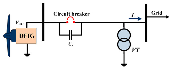
Figure 1.
Connection of VT in a wind generation system.
The schematic representation of the ferroresonance equivalent circuit is shown in Figure 2, where the doubly-fed induction generator (DFIG) is modeled as an AC source connected in series with its Thevenin impedance, and the VT is modeled as a nonlinear inductor in parallel with a resistor (R) and a capacitor, which represents the open breaker, as suggested in [27].
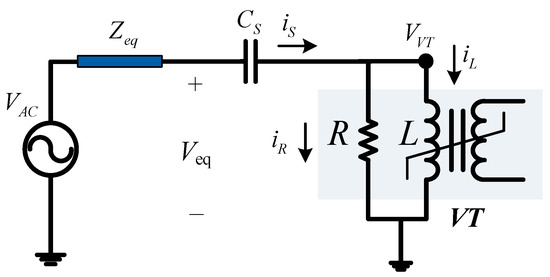
Figure 2.
Simplified equivalent circuit of the wind generation system.
2.1. Analysis of Ferroresonance
In this subsection, the analytical study of the ferroresonance phenomenon is conducted with a focus on the nonlinear behavior of the VT core, which is the primary reason for the occurrence of ferroresonance. The nonlinear behavior of the magnetic flux and the primary coil inductor of the VT is defined mathematically in Equation (1), characterized by an “n” order polynomial function of the VT core flux, , in relation with and , respectively denoting the inductance of VT and the primary winding current [18]. The flux linkage of the VT primary winding, denoted by , is described in Equation (2) [28]. Finally, , as the current in the primary winding of the VT, is derived from Equations (1) and (2) and represented as Equation (3).
Equation (4) represents the equivalent voltage at the ferroresonant circuit as a sinusoidal voltage with an amplitude of , an angular frequency of , and a phase angle of . The losses associated with the core of the VT in Figure 2 are characterized by a resistance , representing the core losses, including the hysteresis and eddy current losses. During the normal conditions in the non-saturated region, the inductance of the VT core is significantly high, and thus, the inductive part of the magnetization current, i.e., is small. However, under saturation conditions, which is the case during ferroresonance, the inductance of the VT core drastically decreases, leading to an abrupt increase of . Although during ferroresonance, the transformer core losses also change with respect to the normal condition, the resistive component of the magnetizing current, i.e., , remains insignificant compared to the excessively increased . On this ground, during the ferroresonance phenomenon, the considerations in Equation (5) are adopted, which assumes that the resistive part of the VT core current is negligible with respect to its inductive component, and accordingly, the voltage source current, i.e., , is approximately equal to [18]. By taking the derivative of Kirchhoff’s Voltage Law (KVL) applied over the loop, including the equivalent voltage, , the capacitor, , and the VT in the equivalent circuit in Figure 2, and yielding , Equation (6) is obtained, describing the behavior of the VT during ferroresonance. It is worth noting that the nonlinearity of the ferroresonance phenomenon is marked in the final term in Equation (6). The nonlinearities involved in the ferroresonance phenomenon can lead to waveform asymmetry, as detailed in [19]. This symmetry breaking occurs mainly due to the phase shift of the voltage source and also the initial conditions of the ferroresonance state, including the capacitor voltage and inductor remanent flux.
2.2. Simulation of Ferroresonance in VT
In this subsection, a simulation of the ferroresonance phenomenon in a wind energy system is performed. The electrical system, as illustrated in Figure 1, is composed of wind generators and their VTs. The simulation focuses on the voltage of VT and the magnetic flux of its core, as they provide valuable insights into the nature of the voltage signal and its relationship with the flux supplied by the wind generator. The magnetic saturation of the VT core is shown in Figure 3, with saturation occurring at approximately 1.8 T. The magnetization curve has been obtained based on measurements on realistic VTs installed in a local utility grid. It is noteworthy that this magnetic behavior is characterized in grain-oriented steel M4. The key system parameters used in the simulation are listed in Table 1.
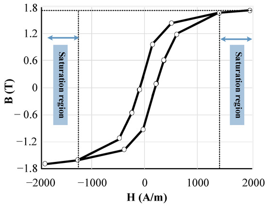
Figure 3.
B-H Curve of the VT core.

Table 1.
Parameters of the simulated system.
In order to quantify the performance of the proposed SSFSC in ferroresonance elimination, several metrics are employed, including the main harmonic component contribution (MHCC) and the rate of voltage rising (RVR), as defined in the following. The CMHC index is defined as the percentage of the main harmonic component magnitude in the total signal, calculated as:
where is the h-th voltage harmonic component. The RVR is defined as the absolute slope of the line connecting two consecutive local extrema in the voltage waveform, as demonstrated in Figure 4 and Equation (8). According to Figure 4, RVR is yielded by:
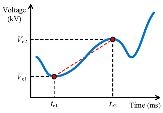
Figure 4.
Definition of RVR.
It is worth mentioning that for a pure sinusoidal voltage waveform in the system under study, the MHCC and RVR indexes are approximately equal to 100% and 10.29 kV/ms, respectively. Therefore, a lower percentage of MHCC would characterize higher harmonic distortion in the voltage, and a higher RVR ratio would indicate sharper voltage spikes, which are undesirable.
In Figure 5, the voltage across the VT in the test system in Figure 2 is demonstrated, where ferroresonance behavior is observed when the circuit breaker opens at t = 200 ms. It is observed that immediately following the opening of the breaker, the voltage of the VT experiences a sudden increase to nearly 2.5 p.u. This nonlinear oscillation persists, resulting in the rapid accumulation of overvoltage, which can potentially cause extensive damage to the VT and other parallel equipment in the wind station. The MHCC index in Figure 5 has dropped to 45%, and its maximum RVR has increased to 28 kV/ms.
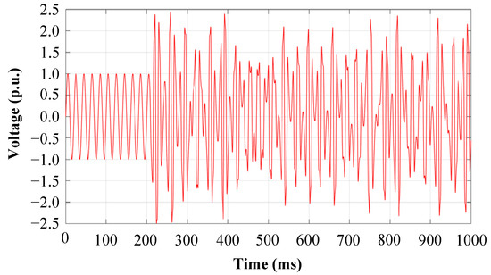
Figure 5.
Voltage waveform of VT in ferroresonance state.
The relation of VT voltage and its magnetic flux is demonstrated in Figure 6, referred to as the Poincaré section of the flux-voltage, where the domain of flux variation is between −3.2 and 3.2 p.u. Moreover, the maximum voltage of VT reaches nearly 2.5 p.u. when the magnetic flux exceeds 1.0 p.u.
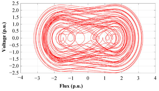
Figure 6.
Flux–voltage Poincaré section of VT under ferroresonance state.
3. Configuration, Analysis, and Simulation of Proposed SSFSC
3.1. SSFSC Configuration and Operation
In this section, the topology of the proposed solid-state ferroresonance suppressing circuit (SSFSC) is presented. The topology of the SSFSC, as depicted in Figure 7, consists of four IGBTs (S1–S4), a capacitor (C), a battery bank, and a battery charging management system. The topology is connected to the secondary winding of the VT and serves to suppress sustained overvoltages caused by ferroresonance.
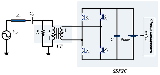
Figure 7.
Configuration of the proposed SSFSC.
As can be seen in Figure 8, the operational sequence of the proposed SSFSC is depicted. The two positive and negative half-cycle operation intervals of the proposed SSFSC are illustrated in Figure 8a,b, respectively, where the corresponding active conduction paths are specified with “red” arrows. The secondary voltage of the VT is continuously monitored and compared with a pre-determined reference value (the comparison threshold is set at ±1.05 p.u.). If the voltage of the secondary winding exceeds 1.0 p.u. during the positive half-cycle, IGBTs S1 and S2 are activated to conduct a reverse current into the secondary winding, according to Figure 8a. This reverse current creates an opposing magnetic flux in the VT core, thereby preventing core saturation and limiting the voltage rise in the VT primary winding. During the negative half-cycle of the voltage, according to Figure 8b, IGBTs S3 and S4 are activated by the control system to perform a similar operation, thus effectively protecting the VT from ferroresonance.
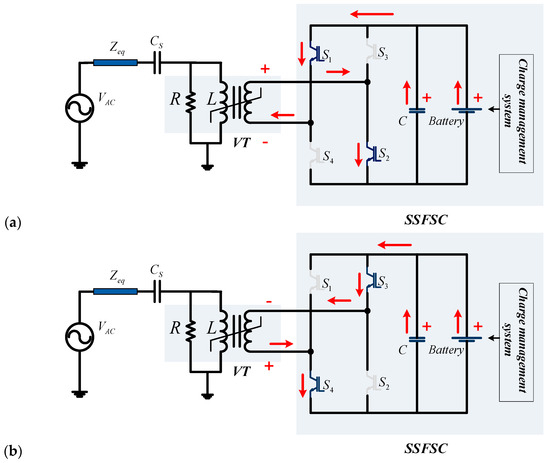
Figure 8.
Operational sequences of SSFSC: (a) Positive half-cycle; (b) Negative half-cycle.
3.2. Analytical Study of SSFSC
The operation of the proposed SSFSC is mathematically verified in this subsection. The focus of the analysis is on the effect of the primary and secondary winding currents on the voltage of the VT. This calculation is performed using the equivalent circuit diagram depicted in Figure 9, which represents the interplay between the total magnetic flux of the VT core and the primary and secondary winding fluxes. It is shown that the primary voltage of the VT is suppressed due to the decrease in the magnetic flux as a result of the reverse direction of the primary and secondary winding fluxes, thus keeping the core of the VT far from the saturation region.
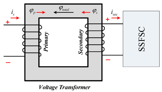
Figure 9.
Effect of SSFSC operation on the magnetic flux of VT.
Throughout this analytical study, the operation of the SSFSC is analyzed by focusing on the voltage of the VT. A mathematical model is developed to calculate the voltage of the VT, taking into account the effect of primary and secondary winding currents on the magnetic flux of the VT core. The analysis begins when the voltage of the secondary winding exceeds 1.05 p.u. At this point, the control system triggers the IGBTs to conduct the charged capacitors to the secondary winding. This results in the generation of a secondary current, , which creates a magnetic flux, , in the opposite direction of the primary winding flux. The total magnetic flux of the VT core, as shown in Equation (9), is the result of the primary winding and secondary winding fluxes. This value is significantly lower than the core saturation flux, which ensures that the core operates in the linear region and the voltage of the primary winding of VT is suppressed. This is demonstrated by Equation (10), which proves the effectiveness of the SSFSC in suppressing ferroresonance in the VT.
Additionally, the secondary winding current, , can be mathematically determined using Equation (11), from which the magnetic flux, , associated with the secondary winding can be derived from the secondary side voltage, , and the voltage across the capacitor unit in SSFSC, , as represented in Equation (12).
3.3. Simulation of SSFSC Operation
Here, the effects of the SSFSC operation on the ferroresonance phenomenon of VT are analyzed through simulation analysis. The simulation parameters consider a secondary voltage of 12 V and a capacitor bank with a capacity of 50 mF charged by a 15 V battery bank. It is to be mentioned that the battery unit should be capable of supplying the current required to cancel the excess magnetomotive force (mmf) in the VT core due to ferroresonance. Additionally, the capacitor bank is responsible for providing the transient energy needed in each duty cycle. If the capacitor’s value is insufficient, the energy stored in the capacitor will discharge during the current injection interval, and the circuit will not perform as intended. Here, practical values have been selected which are attainable with commonly available circuit components. The results of the simulation are presented in Figure 10, which shows the primary voltage of VT when the circuit breaker opens the power line at t = 200 ms. The simulation results demonstrate that the maximum voltage of VT is effectively limited to 1.05 p.u. through the operation of the SSFSC, resulting in a significant improvement in the nonlinear oscillation. Furthermore, the MHCC of the voltage waveform in Figure 10 is increased to 78%, and its maximum RVR is limited to 13.2 kV/ms. The results indicate that the operation of the proposed SSFC during ferroresonance conditions improves the MHCC and RVR indexes to the desired values of 100% and 10.29 kV/ms, respectively.
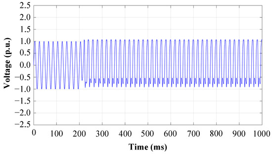
Figure 10.
Effect of SSFSC operation on voltage of VT.
The flux–voltage Poincaré section of VT demonstrated in Figure 11 expresses that the variation range of the magnetic flux is effectively restricted within the bounds of −1.8 p.u. to 2.2 p.u., thereby effectively controlling the nonlinear behavior of the magnetic flux with respect to the voltage.
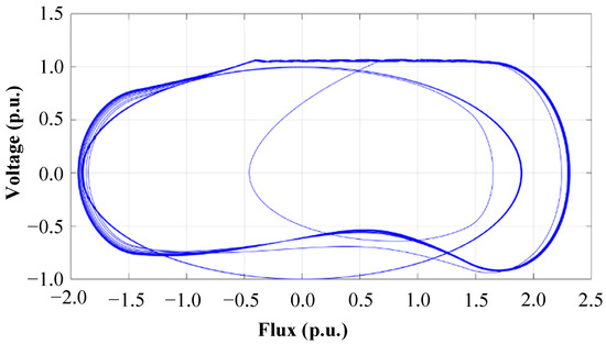
Figure 11.
Effect of SSFSC operation on flux–voltage Poincaré section of VT.
Through simulation studies, the efficacy of the proposed SSFSC in mitigating ferroresonance overvoltage in wind generator systems has been demonstrated. The results show a substantial decline in the nonlinear oscillations and overvoltage peak in the voltage of VT, effectively mitigating the risk of damage to the equipment. These results affirm the viability of SSFSC as a protective solution for wind generator stations against ferroresonance overvoltage.
4. SSFSC Control Strategy
In this section, the control strategy for the SSFSC during the occurrence of ferroresonance is presented. The control signal is based on the voltage of the secondary winding of the VT, which is divided into positive and negative components. These components are then compared against two constant references of 1.05 p.u. and −1.05 p.u. to generate logical pulses for the control of IGBTs S1, S2, S3, and S4. The controller topology of the proposed SSFSC is depicted in Figure 12.
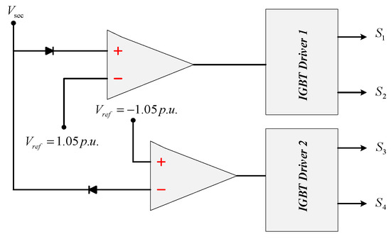
Figure 12.
Topology of the proposed SSFSC controller.
Figure 13 depicts the control signals of SSFSC, which are used to activate the IGBT switches of the bridge configuration. The logical pulse displayed in Figure 13a corresponds to switches S1 and S2, while the pulse shown in Figure 13b corresponds to switches S3 and S4. These control pulses are generated based on the comparison between the voltage of VT and the two above-mentioned constant references.
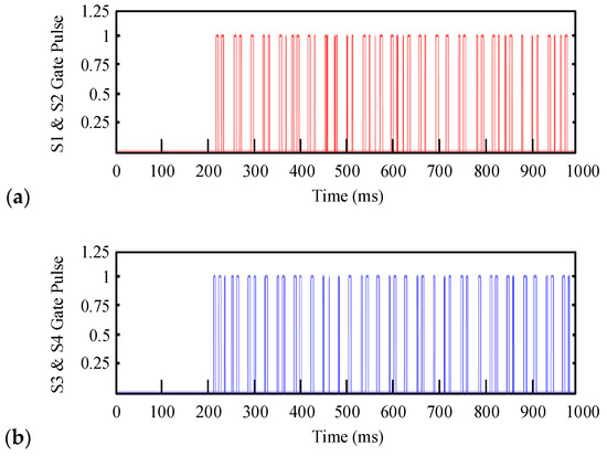
Figure 13.
SSFSC logical control signals: (a) Logical pulses of S1 and S2; (b) Logical pulses of S3 and S4.
In response to the fired pulses, the IGBT switches start conducting. Considering the resistive and inductive (RL) nature of the VT secondary as the bridge load, the switch currents will be in the form of exponentials, as shown in Figure 14, illustrating the switch currents in the interval between 200 ms and 300 ms.
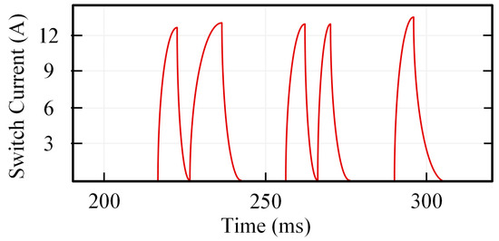
Figure 14.
Switch current waveform.
5. Results Discussion and Comparison
5.1. Performance of the Proposed SSFSC
In this section, the main achievements of the proposed SSFSC and its operational capabilities are presented and discussed. Table 2 presents a summary of the SSFSC capabilities by comparing VT parameters with and without the proposed SSFSC under the ferroresonance condition.
Table 2.
Comparison of VT parameters with and without SSFSC.
The comparison results in Table 2 indicate that the implementation of the SSFSC protection device for the mitigation of ferroresonance in the wind generator station results in a significant reduction in the peak voltage by 58%, a reduction in the magnetic flux of the VT core by 31.25%, a reduction in the RVR by 54%, and an increase in the main harmonic of the voltage signal by 33%.
Moreover, it should be mentioned that the proposed SSFSC offers a significant advantage with its operation at a low voltage level, which avoids the high-cost and specialized requirements associated with high-voltage equipment. Contrarily, it can be constructed using inexpensive electronic components and circuitry, applying an uncomplex control strategy based on operational amplifiers. On the other hand, given that the VT is a shunt-connected device, the ferroresonance-induced overvoltage can impact other components, such as wind generators and power transformers, potentially leading to large-scale system failures extending to generators and power transformers. In such scenarios, additional costs may arise due to unsupplied energy during resulting power outages. Therefore, the significance of applying a low-voltage, uncomplicated, and cost-effective protective circuit becomes evident when considering the substantial costs associated with potential large-scale failures and the resulting loss of supplied energy.
5.2. Comparison with State-of-the-Art
Together with the proposed SSFSC, the most important approaches proposed in the literature toward ferroresonance suppression in VTs are based on four particular approaches. These techniques are namely (i) the employment of a surge arrester, as in [23], (ii) the application of Chaos theory, as in [21], (iii) utilizing the solid-state circuit presented in [26], and finally, (iv) the SSFSC proposed in the put-forward analysis. The employment of surge arresters [23] is a high-voltage solution that introduces high power loss and is associated with the risk of insufficient energy withstanding the capacity and, thus, surge arrester failure. In the second approach [21], a complex controller based on Chaos theory was proposed, which not only is again a high-voltage solution, but also is associated with high levels of complexity. In the third technique [26], a promising solid-state circuit was proposed to suppress ferroresonance in VTs. However, this technique is also a high-voltage solution and involves complex circuitry and controls. The advantage of the proposed SSFSC is to suppress VT ferroresonance based on solid-state circuitry with simple and uncomplex topology and control, while being easily applicable at a low voltage with low power loss. The advantages of the proposed SSFSC in comparison with other available solutions, are highlighted in Table 3. As marked in Table 3, the proposed SSFSC provides excellent VT ferroresonance capabilities even in comparison with the state-of-the-art.
Table 3.
Performance comparison with the state-of-the-art.
6. Conclusions
The present study successfully proposes an innovative SSFSC for the protection of VTs in wind generation systems from the harmful effects of ferroresonance. Ferroresonance leads to overvoltage and distorted waveforms, which can cause significant damage to the equipment. The SSFSC proposed in the paper utilizes low-voltage circuits, including power IGBTs, and can be installed in the secondary of VTs. The performance of the SSFSC is validated through detailed analytical studies and time-domain simulations using a wind generation system model in MATLAB/Simulink. The results of detailed analysis and simulation indicate that the SSFSC can effectively suppress ferroresonance overvoltages and reduce the peak voltage by 58%, the magnetic flux by 31.25%, RVR by 54%, and the main harmonic of voltage by 33%. The proposed SSFSC, therefore, provides an effective solution for mitigating the adverse effects of ferroresonance in wind generation systems. Based on the obtained results, it can be concluded that the proposed SSFSC exhibits exceptional performance in suppressing ferroresonance overvoltage in wind energy system VTs with fast operational speeds.
Author Contributions
Conceptualization, A.B., M.B. and M.M.; investigation, A.B.; methodology, A.B.; writing—original draft preparation, A.B.; writing—review and editing, B.B. and M.H.; supervision, M.B., M.M., B.B. and M.H.; interpretation of data, M.B. and M.M.; accuracy and integrity assurance, M.B., M.M. and M.H.; validation, B.B.; final approval, M.H. All authors have read and agreed to the published version of the manuscript.
Funding
This research received no external funding.
Data Availability Statement
Data will be made available on request.
Conflicts of Interest
The authors declare no conflict of interest.
Nomenclature
| total core flux | resistive current of VT | ||
| magnetic flux in primary | current at VT secondary | ||
| magnetic flux in secondary | system equivalent resistance | ||
| flux linkage | system equivalent inductance | ||
| order of magnetizing characteristic | circuit breaker grading capacitance | ||
| inductance of primary winding | VT primary side voltage | ||
| voltage of wind generator station | VT secondary side voltage | ||
| equivalent voltage OS system | SSFSC capacitor voltage | ||
| equivalent voltage amplitude | primary winding turns number | ||
| angular frequency | secondary winding turns number | ||
| time | voltage harmonic of order | ||
| equivalent voltage angle | reluctance of core | ||
| wind source current | secondary winding resistance | ||
| inductive current of VT | charged voltage of capacitor |
References
- Karaagac, U.; Mahseredjian, J.; Cai, L. Ferroresonance conditions in wind parks. Electr. Power Syst. Res. 2016, 138, 41–49. [Google Scholar] [CrossRef]
- Zhang, Y.; Muljadi, E.; Kosterev, D.; Singh, M. Wind power plant model validation using synchrophasor measurements at the point of interconnection. IEEE Trans. Sustain. Energy 2014, 6, 984–992. [Google Scholar] [CrossRef]
- Akinrinde, A.; Swanson, A.; Tiako, R. Dynamic behavior of wind turbine generator configurations during ferroresonant conditions. Energies 2019, 12, 639. [Google Scholar] [CrossRef]
- Milicevic, K.; Emin, Z. Initiation of characteristic ferroresonance states based on flux reflection model. IEEE Trans. Circuits Syst. II Express Briefs 2013, 60, 51–55. [Google Scholar] [CrossRef]
- Ding, X.; Yang, K.; Wang, W.; Liu, B.; Wang, X.; Zhang, J.; Li, D. Ferro-resonance analysis of capacitor voltage transformer with fast saturation damper. Energies 2022, 15, 2791. [Google Scholar] [CrossRef]
- Iravani, M.; Chaudhary, A.; Giesbrecht, W.; Hassan, I.; Keri, A.; Lee, K.; Martinez, J.; Morched, A.; Mork, B.; Parniani, M.; et al. Modeling and analysis guidelines for slow transients. III. The study of ferroresonance. IEEE Trans. Power Deliv. 2000, 15, 255–265. [Google Scholar] [CrossRef]
- Tajdinian, M.; Allahbakhshi, M.; Behdani, B.; Behi, D.; Goodarzi, A. Probabilistic framework for vulnerability analysis of coupling capacitor voltage transformer to ferroresonance phenomenon. IET Sci. Meas. Technol. 2020, 14, 344–351. [Google Scholar] [CrossRef]
- Wang, Y.; Liang, X.; Pordanjani, I.R.; Cui, R.; Jafari, A.; Clark, C. Investigation of ferroresonance causing sustained high voltage at a DE-energized 138 kV bus: A case study. IEEE Trans. Ind. Appl. 2019, 55, 5675–5686. [Google Scholar] [CrossRef]
- Zirka, S.; Moroz, Y.; Zhuykov, A.; Matveev, D.; Kubatkin, M.; Frolov, M.; Popov, M. Eliminating VT uncertainties in modeling ferroresonance phenomena caused by single phase-to-ground faults in isolated neutral network. Int. J. Electr. Power Energy Syst. 2021, 133, 107275. [Google Scholar] [CrossRef]
- Kraszewski, W.; Syrek, P.; Mitoraj, M. Methods of ferroresonance mitigation in voltage transformers in a 30 kV power supply network. Energies 2022, 15, 9516. [Google Scholar] [CrossRef]
- Wang, B.; Zhang, C.; Xia, Y.; Zhang, F. Analytical solution of serial ferroresonance triggered by circuit breaker operation in solidly grounded power grids. Int. J. Electr. Power Energy Syst. 2023, 154, 109447. [Google Scholar] [CrossRef]
- Heidary, A.; Niasar, M.G.; Popov, M.; Lekić, A. Transformer Resonance: Reasons, Modeling Approaches, Solutions. IEEE Access 2023, 11, 58692–58704. [Google Scholar] [CrossRef]
- Thanomsat, N.; Plangklang, B.; Ohgaki, H. Analysis of ferroresonance phenomenon in 22 kV distribution system with a photovoltaic source by PSCAD/EMTDC. Energies 2018, 11, 1742. [Google Scholar] [CrossRef]
- Abdel-Hamed, A.M.; El-Shafhy, M.M.; Badran, E.A. High Ohmic Reactor as a Shunt Limiter (HOR-SL) Method for Ferroresonance Elimination in the Distribution System. IEEE Access 2022, 10, 134217–134229. [Google Scholar] [CrossRef]
- Bronzeado, H.S.; Emin, Z.; Kocis, L.; Shim, E.B. Review of Ferroresonance Phenomenon on Power Systems: Practical Examples and Experience with Adopted Solutions. In Proceedings of the Cigré International Symposium on Assessing and Improving Power System Security, Reliability and Performance in Light of Changing Energy Sources, Recife, Brazil, 3–6 April 2011. [Google Scholar]
- Sagardia, S.R.; Morched, A. Potential Transformer Failure due to Ferroresonance. In Proceedings of the IPST ’97—International Conference on Power System Transients, Seattle, DC, USA, 22–26 June 1997; Available online: https://www.ipstconf.org/papers/Proc_IPST1997/97IPST030.pdf (accessed on 1 November 2023).
- Emin, Z.; Tong, Y.K. Ferroresonance Experience in UK: Simulations and Measurements. In Proceedings of the IPST 2001—International Conference on Power System Transients, Rio de Janeiro, Brazil, 24–28 June 2001; Available online: https://www.ipstconf.org/papers/Proc_IPST2001/01IPST044.pdf (accessed on 1 November 2023).
- Heidary, A.; Rouzbehi, K.; Radmanesh, H.; Pou, J. Voltage Transformer Ferroresonance: An Inhibitor Device. IEEE Trans. Power Deliv. 2020, 35, 2731–2733. [Google Scholar] [CrossRef]
- Milicevic, K.; Vulin, D.; Vinko, D. Experimental investigation of symmetry-breaking in ferroresonant circuit. IEEE Trans. Circuits Syst. I Regul. Pap. 2014, 61, 1543–1552. [Google Scholar] [CrossRef]
- Rezaei-Zare, A.; Etemadi, A.H.; Iravani, R. Challenges of power converter operation and control under ferroresonance conditions. IEEE Trans. Power Deliv. 2016, 32, 2380–2388. [Google Scholar] [CrossRef]
- Fordoei, H.R.A.; Gholami, A.; Fathi, S.H.; Abbasi, A. Chaotic oscillations control in the voltage transformer including nonlinear core loss model by a nonlinear robust adaptive controller. Int. J. Electr. Power Energy Syst. 2013, 47, 280–294. [Google Scholar] [CrossRef]
- Behdani, B.; Allahbakhshi, M.; Tajdinian, M. On the impact of geomagnetically induced currents in driving series capacitor compensated power systems to ferroresonance. Int. J. Electr. Power Energy Syst. 2020, 125, 106424. [Google Scholar] [CrossRef]
- Radmanesh, H.; Gharehpetian, G.B.; Fathi, H. Ferroresonance of power transformers considering nonlinear core losses and metal oxide surge arrester effects. Electr. Power Compon. Syst. 2012, 40, 463–479. [Google Scholar] [CrossRef]
- Heidary, A.; Radmanesh, H.; Bakhshi, A.; Samandarpour, S.; Rouzbehi, K.; Shariati, N. Compound ferroresonance overvoltage and fault current limiter for power system protection. IET Energy Syst. Integr. 2020, 2, 325–330. [Google Scholar] [CrossRef]
- Radmanesh, H.; Heidary, A.; Fathi, S.H.; Gharehpetian, G.B. Dual function ferroresonance and fault current limiter based on DC reactor. IET Gener. Transm. Distrib. 2016, 10, 2058–2065. [Google Scholar] [CrossRef]
- Heidary, A.; Radmanesh, H. Smart solid-state ferroresonance limiter for voltage transformers application: Principle and test results. IET Power Electron. 2018, 11, 2545–2552. [Google Scholar] [CrossRef]
- Torres-García, V.; Solís-Ramos, N.; González-Cabrera, N.; Hernández-Mayoral, E.; Guillen, D. Ferroresonance Modeling and Analysis in Underground Distribution Feeders. IEEE Open Access J. Power Energy 2023, 10, 583–592. [Google Scholar] [CrossRef]
- Chapman, S.J. Electric Machinery Fundamentals, 5th ed.; McGraw Hill Higher Education: Maidenhead, UK, 2011. [Google Scholar]
Disclaimer/Publisher’s Note: The statements, opinions and data contained in all publications are solely those of the individual author(s) and contributor(s) and not of MDPI and/or the editor(s). MDPI and/or the editor(s) disclaim responsibility for any injury to people or property resulting from any ideas, methods, instructions or products referred to in the content. |
© 2023 by the authors. Licensee MDPI, Basel, Switzerland. This article is an open access article distributed under the terms and conditions of the Creative Commons Attribution (CC BY) license (https://creativecommons.org/licenses/by/4.0/).