
Inverse Design of Axis Fan for Permanent Magnet Drive Motor for Special Vehicles


Abstract
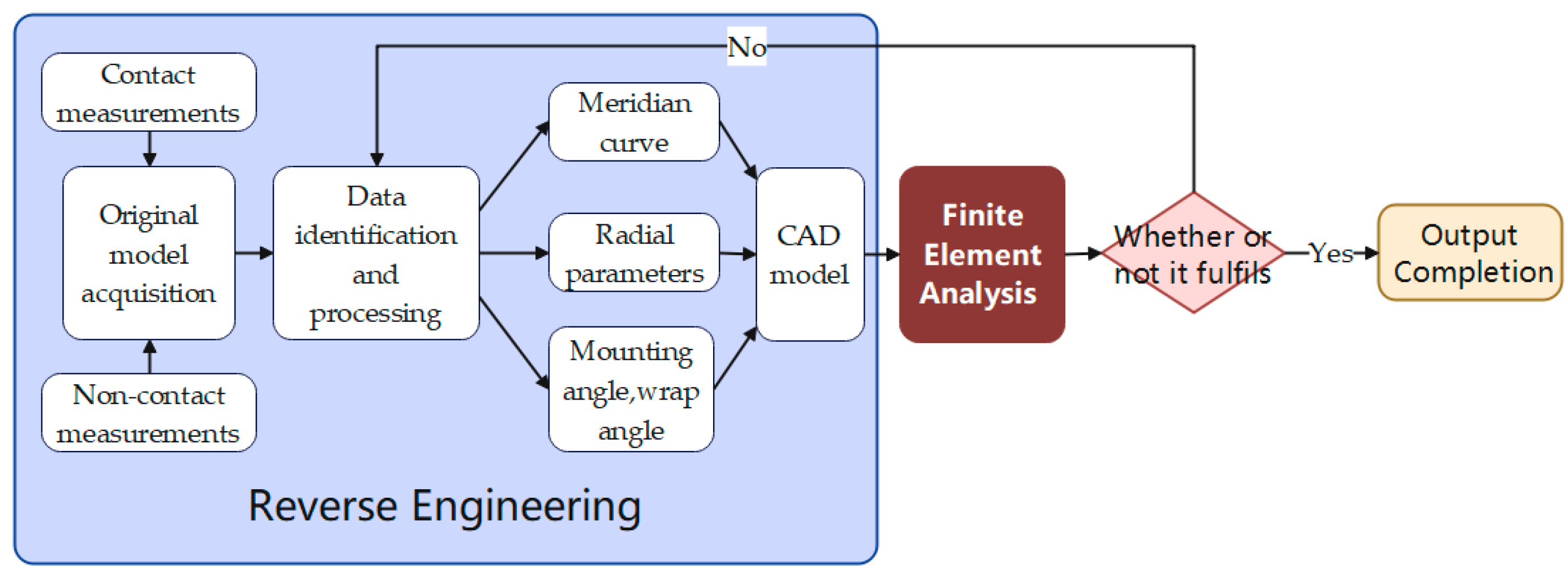
:1. Introduction
2. Motor Axis Fan Model and Basic Theory
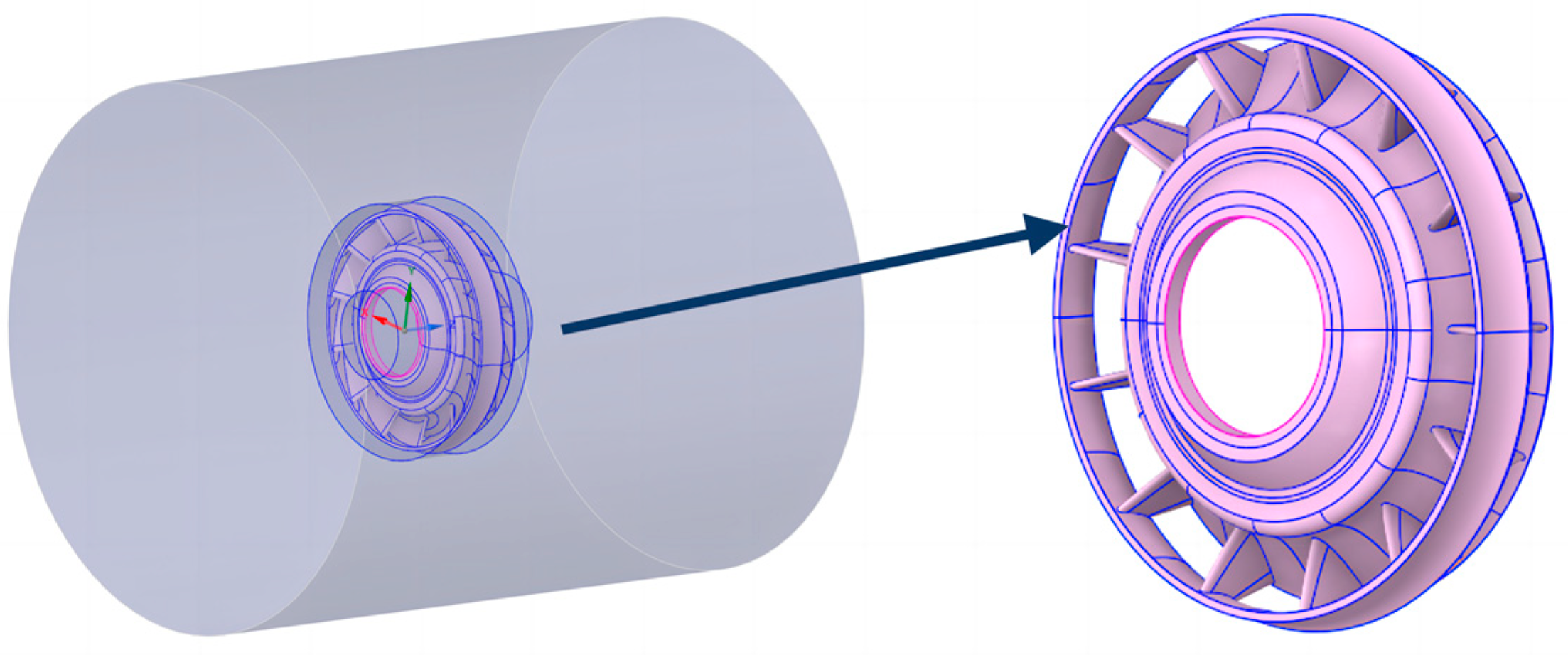
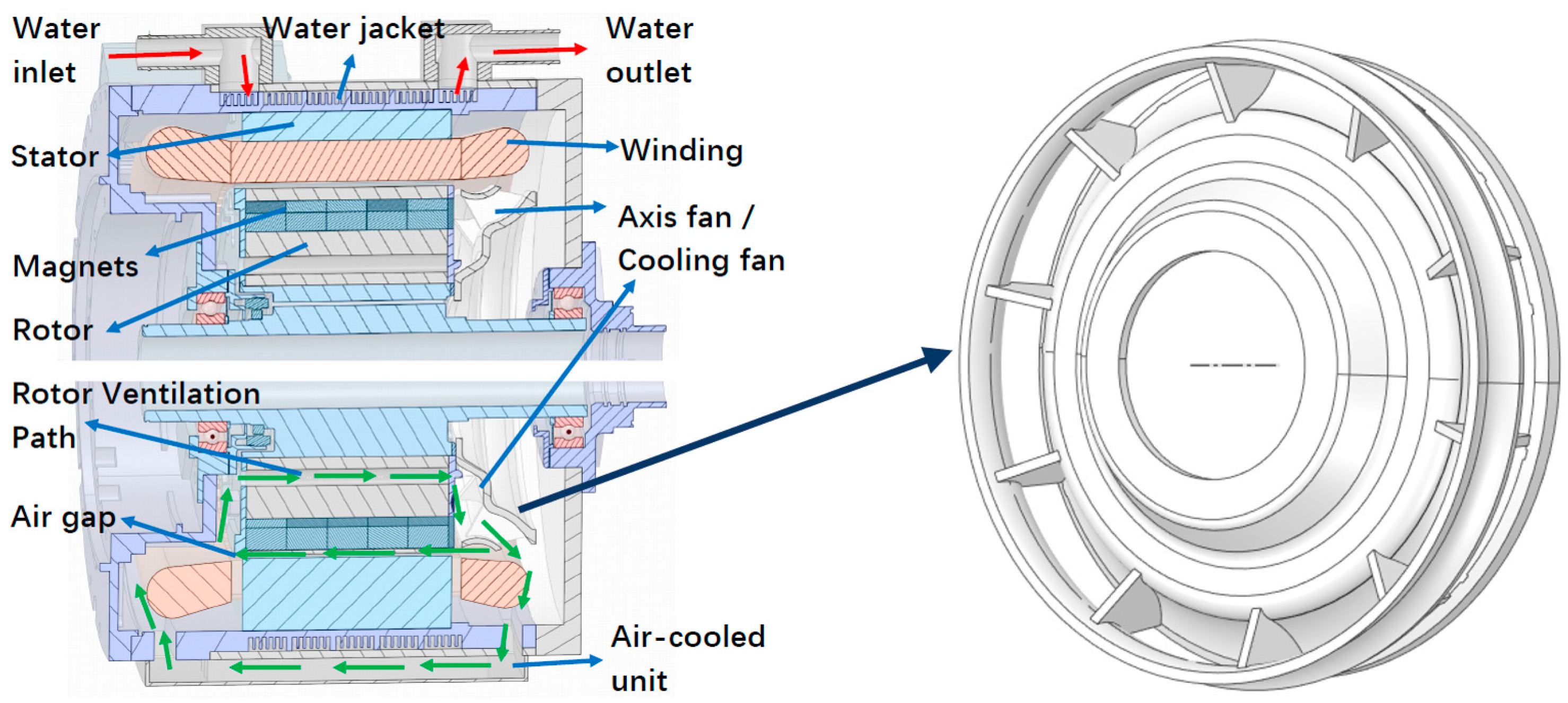
2.1. Motor Overall Structure and Cooling Fan Model
2.2. Calculation of Mechanical Energy Loss in Electric Motors
3. Basic Theory of Fan Blades
3.1. Calculation of Fan Blades and Flow Rate Based on Empirical Equations
3.2. Number of Leaf Blades
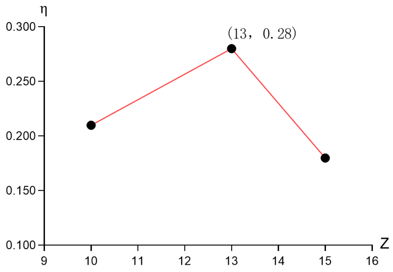
3.3. Specific Speed
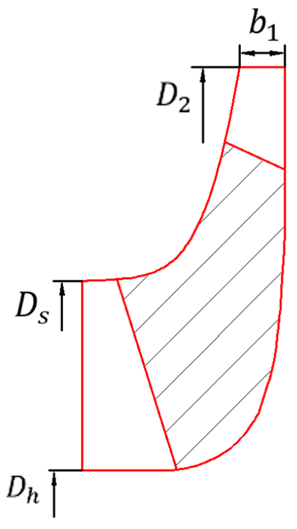
3.4. Determination of Blade Meridian Surfaces
4. Theory Related to Finite Element Fluid-Structure Coupling Calculations
5. Inverse Design Motor Fan and Optimisation Analysis
5.1. Fan Model Reconstruction
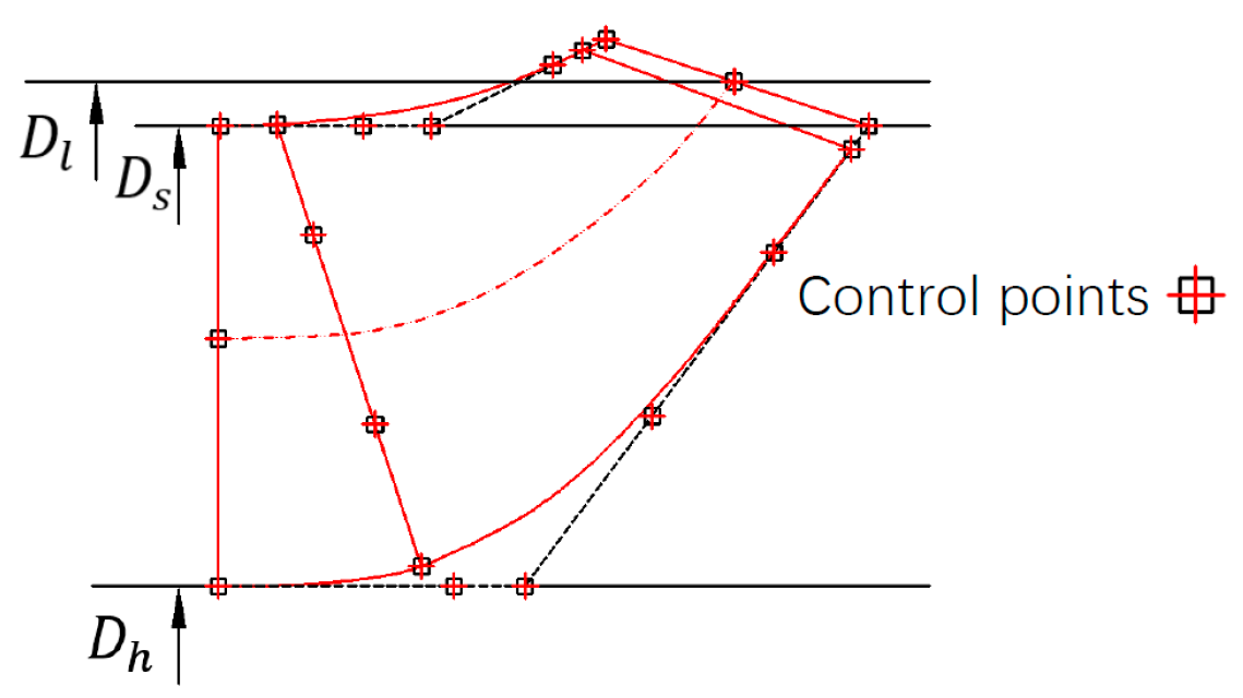
5.1.1. Inverse Meridian Schematic
5.1.2. Fan Radial Main Parameters
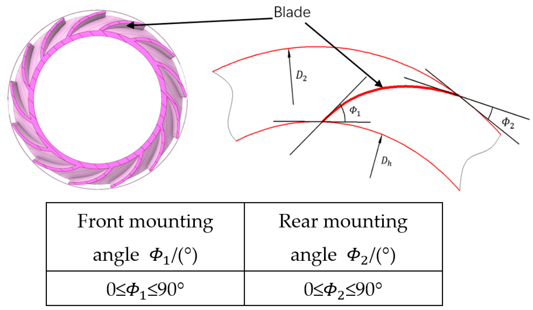
5.1.3. Inverse Model Front and Rear Mounting Angles
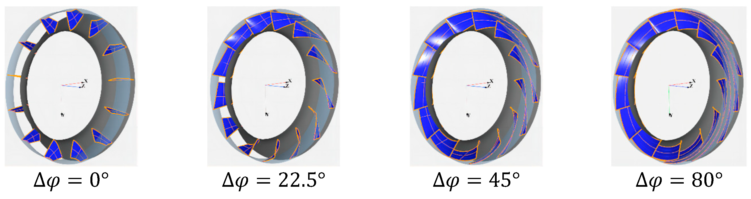
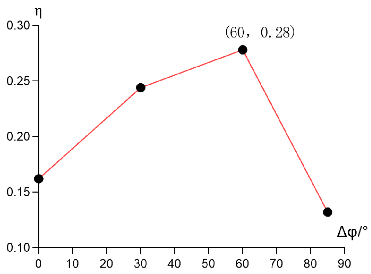
5.1.4. Impeller Wrap Angle Parameter
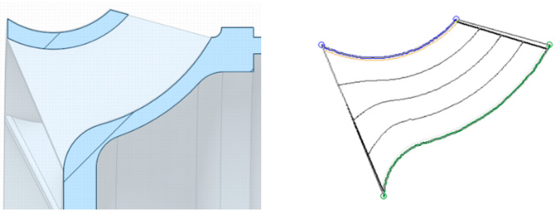
5.1.5. Optimisation of Impeller Rim Edge
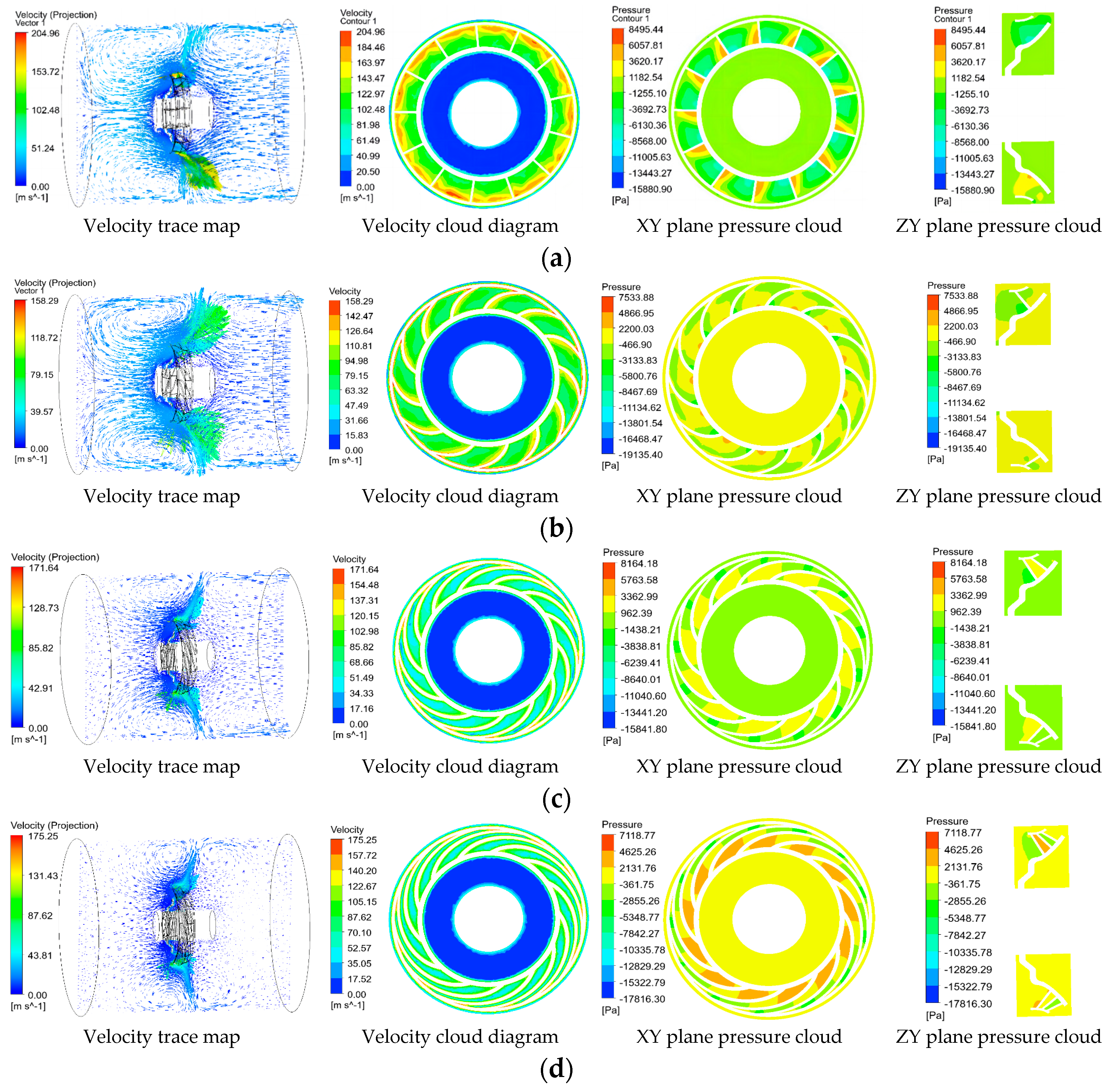
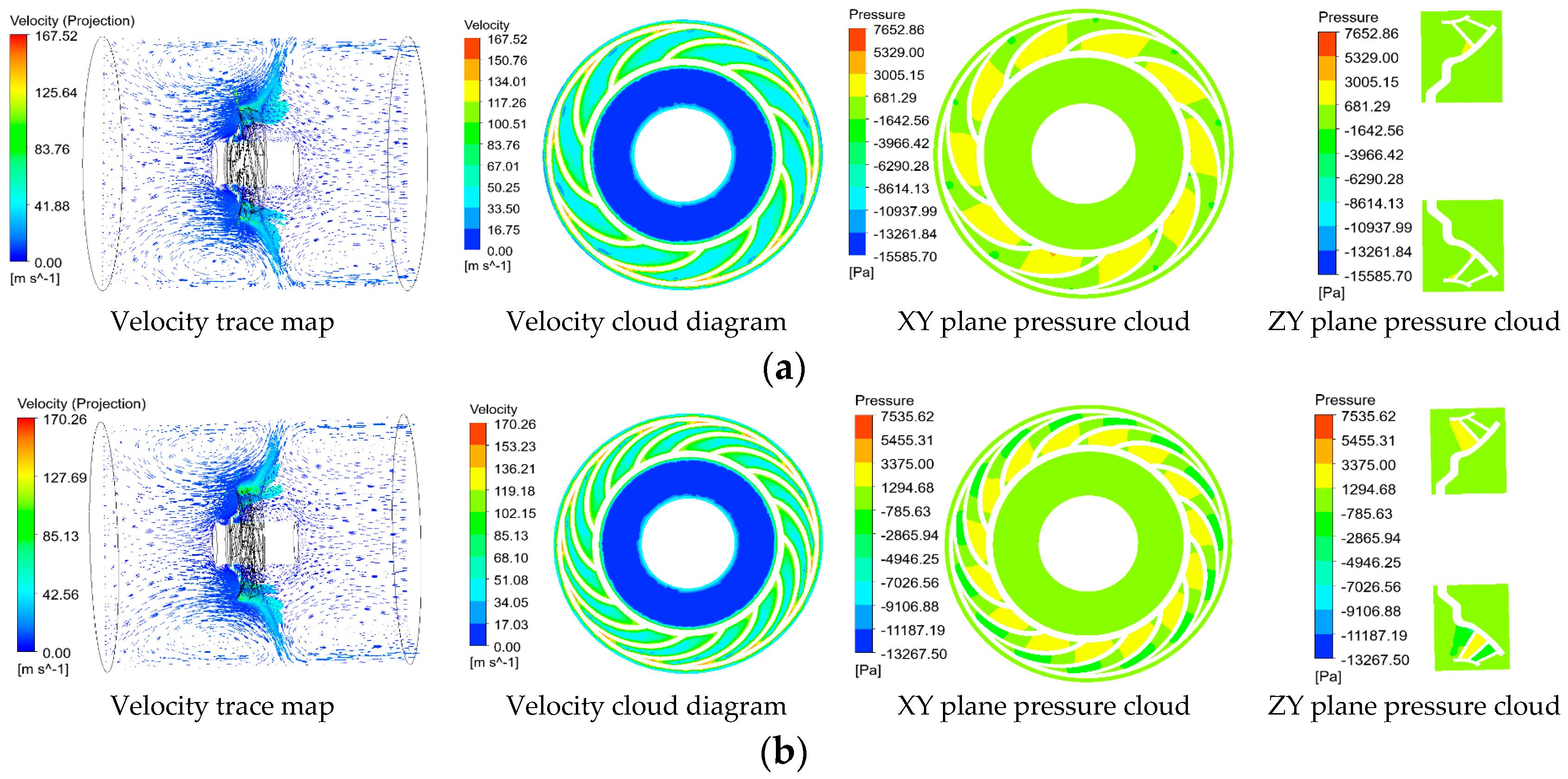
5.2. Simulation Analysis and Optimisation of Fan External Flow Field
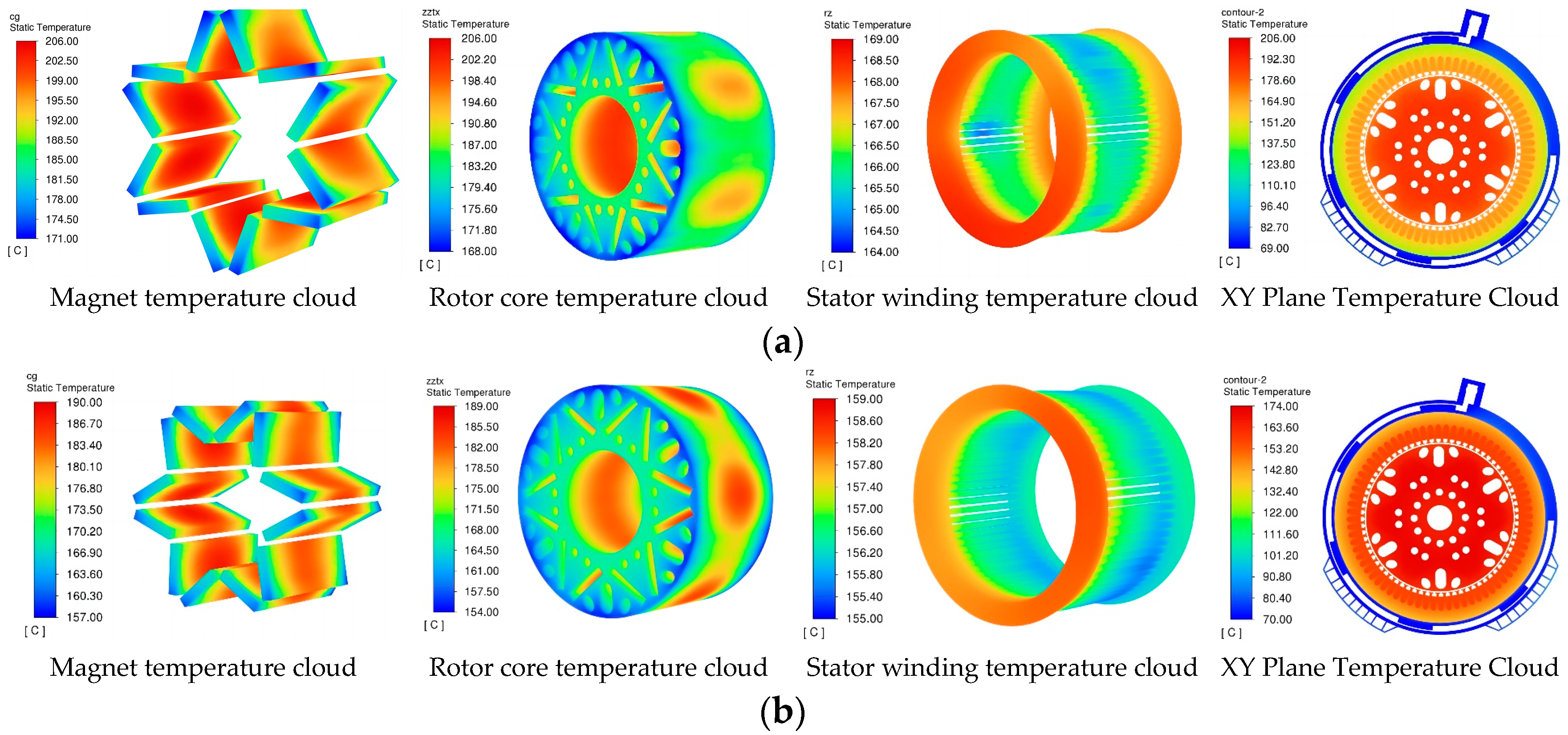
5.3. Comparative Simulation Analysis of Motor Temperature Field
6. Conclusions
Author Contributions
Funding
Conflicts of Interest
References
- Woo, J.-H.; Lee, J.-K.; Choi, J.; Kim, H.; Lee, J. Design of V-type IPMSM for a military vehicle which takes consideration of the output characteristic on the high speed. In Proceedings of the 2016 19th International Conference on Electrical Machines and Systems (ICEMS), Chiba, Japan, 13–16 November 2016; pp. 1–4. [Google Scholar]
- Espanet, C.; Kauffmann, J.-M.; Bernard, R. Comparison of Two In-Wheel Permanent Magnet Motors for Military Applications. In Proceedings of the 2006 IEEE Vehicle Power and Propulsion Conference, Windsor, UK, 6–8 September 2006; IEEE: Piscataway, NJ, USA, 2006; pp. 1–6. [Google Scholar]
- Li, W.; Cao, Z.; Zhang, X. Thermal Analysis of the Solid Rotor Permanent Magnet Synchronous Motors with Air-Cooled Hybrid Ventilation Systems. IEEE Trans. Ind. Electron. 2022, 69, 1146–1156. [Google Scholar] [CrossRef]
- Liu, F.; Wang, X.; Xing, Z.; Ren, J.; Li, X. Analysis and Research on No-Load Air Gap Magnetic Field and System Multiobjective Optimization of Interior PM Motor. IEEE Trans. Ind. Electron. 2022, 69, 10915–10925. [Google Scholar] [CrossRef]
- Jiang, W.; Jahns, T.M. Coupled Electromagnetic–Thermal Analysis of Electric Machines Including Transient Operation Based on Finite-Element Techniques. IEEE Trans. Ind. Appl. 2015, 51, 1880–1889. [Google Scholar] [CrossRef]
- Li, J.; Gao, J.; He, Z.; Huang, S.; Hu, C.; Wu, Y. Analysis of Fluid Field and Temperature Field of Permanent Magnet Synchronous Motor for Special Vehicles. In Proceedings of the 2023 2nd International Conference on Mechatronics and Electrical Engineering (MEEE), Abu Dhabi, United Arab Emirates, 10–12 February 2023; IEEE: Piscataway, NJ, USA, 2023; pp. 1–5. [Google Scholar]
- Sciascera, C.; Giangrande, P.; Papini, L.; Gerada, C.; Galea, M. Analytical Thermal Model for Fast Stator Winding Temperature Prediction. IEEE Trans. Ind. Electron. 2017, 64, 6116–6126. [Google Scholar] [CrossRef]
- Mellor, P.H.; Yon, J.; Baker, J.L.; North, D.; Booker, J.D. Electromagnetic and thermal coupling within a fault-tolerant aircraft propulsion motor. In Proceedings of the IEEE International Electric Machines and Drives Conference, Miami, FL, USA, 21–24 May 2017; pp. 1–7. [Google Scholar]
- Bonnett, H. Operating temperature considerations and performance characteristics for IEEE 841 motors. IEEE Trans. Ind. Appl. 2001, 37, 1120–1131. [Google Scholar] [CrossRef]
- Albers, T.; Bonnett, A.H. Motor temperature considerations for pulp and paper mill applications. IEEE Trans. Ind. Appl. 2002, 38, 1701–1713. [Google Scholar] [CrossRef]
- Bellettre, J.; Sartre, V.; Biais, F.; Lallemand, A. Transient state study of electric motor heating and phase change solid-liquid cooling. Appl. Thermal Eng. 1997, 17, 17–31. [Google Scholar] [CrossRef]
- Sun, Z. Design and Temperature Rise Calculation of Permanent Magnet Propulsion Motor for 350kW Tank. Master’s Thesis, Shenyang University of Technology, Shenyang, China, 2018. [Google Scholar]
- Gai, Y.; Kimiabeigi, M.; Chuan Chong, Y.; Widmer, J.D.; Deng, X.; Popescu, M.; Goss, J.; Staton, D.A.; Steven, A. Cooling of Automotive Traction Motors: Schemes, Examples, and Computation Methods. IEEE Trans. Ind. Electron. 2019, 66, 1681–1692. [Google Scholar] [CrossRef]
- Huang, J.; Shoai Naini, S.; Miller, R.; Rizzo, D.; Sebeck, K.; Shurin, S.; Wagner, J. A Hybrid Electric Vehicle Motor Cooling System—Design, Model, and Control. IEEE Trans. Veh. Technol. 2019, 68, 4467–4478. [Google Scholar] [CrossRef]
- Li, H. Cooling of a permanent magnet electric motor with a centrifugal impeller. Int. J. Heat Mass Transf. 2010, 53, 797–810. [Google Scholar] [CrossRef]
- Kim, C.; Lee, K.-S.; Yook, S.-J. Effect of air-gap fans on cooling of windings in a large-capacity, high-speed induction motor. Appl. Therm. Eng. 2016, 100, 658–667. [Google Scholar] [CrossRef]
- Gebauer, M.; Blejchař, T.; Brzobohatý, T.; Karásek, T.; Nevřela, M. Determination of Aerodynamic Losses of Electric Motors. Symmetry 2022, 14, 2399. [Google Scholar] [CrossRef]
- Galloni, E.; Parisi, P.; Marignetti, F.; Volpe, G. CFD analyses of a radial fan for electric motor cooling. Therm. Sci. Eng. Prog. 2018, 8, 470–476. [Google Scholar] [CrossRef]
- Nakahama, T.; Biswas, D.; Kawano, K.; Ishibashi, F. Improved Cooling Performance of Large Motors Using Fans. IEEE Trans. Energy Convers. 2006, 21, 324–331. [Google Scholar] [CrossRef]
- Lee, K.-H.; Cha, H.-R.; Kim, Y.-B. Development of an interior permanent magnet motor through rotor cooling for electric vehicles. Appl. Therm. Eng. 2016, 95, 348–356. [Google Scholar] [CrossRef]
- Nakahama, T.; Suzuki, K.; Hashidume, S.; Ishibashi, F.; Hirata, M. Cooling Airflow in Unidirectional Ventilated Open-Type Motor for Electric Vehicles. IEEE Trans. Energy Convers. 2006, 21, 645–651. [Google Scholar] [CrossRef]
- Shao, Y.F. Inverse Design and Performance Analysis of a High-Speed Motor Fan Structure. Master’s Thesis, Shenyang University of Technology, Shenyang, China, 2021. [Google Scholar]
- Wang, J.Q. Research on Reverse Design and Key Technology Based on Curved Surface of Unpowered Exhaust Fan Blade. Master’s Thesis, North University of Technology, Beijing, China, 2009. [Google Scholar]
- Gong, C. Research and Modification Design of Automotive Cooling Fan Blade Based on Reverse Engineering. Master’s Thesis, Yanshan University, Qinhuangdao, China, 2012. [Google Scholar]
- Jim, C. Reverse Modelling and Optimal Design of Automotive Engine Blade. Master’s Thesis, Nanjing University of Aeronautics and Astronautics, Nanjing, China, 2009. [Google Scholar]
- Liu, F.; Li, Z.; Huang, J. Consideration of a new fan structure for an ultra-high efficiency motor. Electr. Mach. Control Appl. 2010, 37, 18–20. [Google Scholar]
- Chapman, S.J. Electirc Machinery Fundamentals; Publishing House of Electronics Industry: Beijing, China, 2014. [Google Scholar]
- Zaher, I.; Rodriguez, R.; Sayed, E.; Callegaro, A.; Goykhman, M.; Emadi, A. Effect of Rotor Geometry on Rotor Air Cooling of a Ventilated Axial-Flux Permanent Magnet Machine. In Proceedings of the 2021 IEEE Transportation Electrification Conference & Expo (ITEC), Chicago, IL, USA, 21–25 June 2021; IEEE: Piscataway, NJ, USA, 2021; pp. 77–82. [Google Scholar]
- Shang, J. Handbook of Practical Technology of Ventilators; China Machine Press: Beijing, China, 2011. [Google Scholar]
- Eck, B. Fans: Design and Operation of Centrifugal, Axial-Flow, and Cross-Flow Fans; Pergamon Press: Berlin, Germany, 1973. [Google Scholar]
- Cheng, X. Vane Pump-Ventilator-Compressor (Principle, Design, Operation, Strength); China Machine Press: Beijing, China, 2011. [Google Scholar]
- Li, Y.; Chen, D.; Dai, L. Preferred design of radial turbine blade radial surface profile. J. Eng. Thermophys. 2013, 34, 853–857. [Google Scholar]
- Zhang, D.S.; Zhang, Q.H.; Shi, W.D. Fundamentals and Applications of Numerical Simulation for Vane Pump Design; China Machine Press: Beijing, China, 2015. [Google Scholar]
- Rui, Z. Simulation and Optimisation of Fan and Impeller Field Based on CFD. Master’s Thesis, Southeast University, Nanjing, China, 2016. [Google Scholar]
- Pyrhönen, J.; Jokinen, T.; Hrabovcová, V. Design of Rotating Electrical Machines; China Machine Press: Beijing, China, 2018. [Google Scholar]


| Parameters | Schema | |
|---|---|---|
| 295.3 | 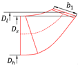 | |
| 302.0 | ||
| 217.2 | ||
| 25.1 |
| Item | Edge | Wrap Angle Δφ/(°) | Front Mounting Angle Φ1/(°) | Rear Mounting Angle Φ2/(°) | 3D Model | |
|---|---|---|---|---|---|---|
| Before optimisation | Right angle | 0 | 10 | 90 | 90 |  |
| After optimisation | Bezier’s angle | 60 | 13 | 45 | 30 |  |
| Components | Loss (W) | Volumes (m3) | Heat Generation Rate (W/m3) |
|---|---|---|---|
| Winding copper consumption | 5080 | 0.0098 | 518,367.3 |
| Stator iron consumption | 2630 | 0.0098 | 268,367.3 |
| Rotor iron consumption | 486 | 0.0068 | 71,470.6 |
| Magnets | 1000 | 0.0021 | 476,190.5 |
| Position | Boundary Conditions | Value |
|---|---|---|
| Water inlet | Velocity inlet | 2.04 m/s, 70 °C |
| Water outlet | Pressure outlet | 1 Pa |
| Outer wall surface of housing | Natural Convection heat Dissipation | 10 W/(m2 · K), 70 °C |
| Rotating part | Field of rotation | 9000 rev/min |
| Water jacket and stator OD contact surface | Coupling surface | 0.5 mm, 0.21 W/(m · K) |
| Maximum Magnet Temperature /(°C) | Maximum Winding Temperature /(°C) | Maximum Temperature Rise ΔT/(K) | Mechanical Energy Loss /(kW) | ||
|---|---|---|---|---|---|
| Before optimisation | 205.4 | 168.5 | 135.4 | 8.0 | 94.2% |
| After optimisation | 188.7 | 158.3 | 118.7 | 2.54 | 96.1% |
| Motor Main Structure Parameters | Main Structural Parameters of Fan | ||
|---|---|---|---|
| Parameter | Value | Parameter | Value |
| Rated power (kW) | 350 | shaft diameter size (mm) | 217.2 |
| Rated speed (r/min) | 9000 | impeller inlet diameter (mm) | 295.3 |
| Stator outer diameter (mm) | 450 | outer diameter size (mm) | 302 |
| Stator inner diameter (mm) | 320 | Wrap angle (°) | 60 |
| Rotor outer diameter (mm) | 314 | Blade number | 13 |
| Iron core length (mm) | 180 | Front mounting angle (°) | 45 |
| Number of pole pairs | 3 | Rear mounting angle (°) | 30 |
Disclaimer/Publisher’s Note: The statements, opinions and data contained in all publications are solely those of the individual author(s) and contributor(s) and not of MDPI and/or the editor(s). MDPI and/or the editor(s) disclaim responsibility for any injury to people or property resulting from any ideas, methods, instructions or products referred to in the content. |
© 2023 by the authors. Licensee MDPI, Basel, Switzerland. This article is an open access article distributed under the terms and conditions of the Creative Commons Attribution (CC BY) license (https://creativecommons.org/licenses/by/4.0/).
Share and Cite
Ma, C.; Li, C.; Liu, K.; He, Z.; Pang, D.; Hua, W. Inverse Design of Axis Fan for Permanent Magnet Drive Motor for Special Vehicles. Energies 2023, 16, 7685. https://doi.org/10.3390/en16237685
Ma C, Li C, Liu K, He Z, Pang D, Hua W. Inverse Design of Axis Fan for Permanent Magnet Drive Motor for Special Vehicles. Energies. 2023; 16(23):7685. https://doi.org/10.3390/en16237685
Chicago/Turabian StyleMa, Changjun, Chunming Li, Kai Liu, Zhixiang He, Daqian Pang, and Wei Hua. 2023. "Inverse Design of Axis Fan for Permanent Magnet Drive Motor for Special Vehicles" Energies 16, no. 23: 7685. https://doi.org/10.3390/en16237685
APA StyleMa, C., Li, C., Liu, K., He, Z., Pang, D., & Hua, W. (2023). Inverse Design of Axis Fan for Permanent Magnet Drive Motor for Special Vehicles. Energies, 16(23), 7685. https://doi.org/10.3390/en16237685