Article

Determination of Dielectric Losses in a Power Transformer

Department of High Voltage and Electrotechnical Materials, Faculty of Environmental Engineering and Energy, Institute of Power Engineering, Poznan University of Technology, 60-965 Poznan, Poland
Energies 2022, 15(3), 993; https://doi.org/10.3390/en15030993
Submission received: 6 December 2021 / Revised: 18 January 2022 / Accepted: 27 January 2022 / Published: 28 January 2022
(This article belongs to the Special Issue Design and Optimization of Power Transformer Diagnostics)

Abstract

:
The article presents a method of determining dielectric losses that occur in insulating materials in a power transformer. These losses depend mainly on the electric field stress, pulsation, dielectric loss coefficient, and electrical permittivity of insulating materials. These losses were determined by integrating an expression describing unit losses. The determined dielectric losses were compared with the total losses of the transformer. It turned out that dielectric losses are a fraction of a percent of the total losses. The influence of the electrical permittivity of the insulating liquid and paper insulation on the value of dielectric losses was investigated. This influence was ambiguous, which is characteristic of stratified systems made of materials with different permittivity. An analysis of the influence of the dielectric loss coefficient tan(delta) on the value of dielectric losses in the transformer was carried out. The impact of this coefficient on the amount of dielectric losses turned out to be directly proportional.

1. Introduction

The reliable operation of the power system determines the reliability of the energy supply to its customers [1,2]. This system is becoming more and more exploited over the years, which is the result of insufficient investment in its modernization [3]. This applies to both transmission lines (overhead lines, cables) and high-voltage substations [4]. On the other hand, the power reserve is decreasing. Both of these phenomena encourage operators to use the power system very prudently. This should be understood as taking into account many technical factors that, in the recent past, have not been taken into account to the same extent as today.
Certainly, one of such factors is the operating temperature of many devices included in the power system. In recent years, temperature has become the cause of threats in the supply of electricity in the summer [5]. This phenomenon has not been observed in previous years. This has to do with the increase in ambient temperature, caused by the increasingly noticeable greenhouse effect. On the other hand, this should be associated with an increasing demand for electricity in the summer, which is the result of an increase in the number of air conditioners [6].
One of the most important elements of the power system is the power transformer. This is evidenced by both its function in the system and the cost of its replacement [7]. The reliable operation of the transformer is conditioned by meeting many requirements. One of them is to maintain a sufficiently low operating temperature. Too-high temperatures can lead to many negative effects [5]. The temperature of the transformer depends on many factors, such as heat sources in the transformer, which are, among other things, the result of losses [8].
In the literature, it is possible to find many articles on dielectric losses or losses in electric power transformers. Unfortunately, the presented research results do not concern dielectric losses in transformers together. For example, in [9], the authors describe only the dielectric losses of traditional (mineral oil) and new insulation liquids (such as esters). They explain which kind of liquid will be characterized by higher dielectric losses, but they do not mention what devices they mean. A similar situation can be seen in a previous paper [10], which is focused on dielectric losses in epoxy polymer and functionally filled silicone rubber (f-SiR) materials. The presented research results concern the dependence of dielectric losses on the electric field stress E. The article does not present dielectric losses in paper or other liquids, and the authors do not determine the dielectric losses in the transformer. Furthermore, the authors of [11] present the results of research that refers only to materials. The authors present various dielectric properties of esters, including tan(delta), which is responsible for the value of dielectric losses. In [12], the authors present results referring to particle layers, employing conductive transition metal nitrides as a proposition of alternative materials for photovoltaic applications in order to decrease losses compared to metal nanostructures. They explain different dielectric properties, such as dielectric losses, but they do not present the value of dielectric losses in any electric power device. In [13,14,15], the authors studied dielectric losses but the results presented refer to an electric power cable. What is more, the articles present dielectric losses in solid insulation, mainly in XLPE, not in paper or other liquids. Another study [16] presents the results of investigations into the losses in an electric power transformer, but the mentioned losses refer to the transformer core, not dielectric losses in the insulation system.
The article analytically determines the dielectric losses of a 220/110 kV electric power transformer, which occur in its insulation system (paper-oil). The authors compared the determined dielectric losses to total losses. The influence of electrical permittivity of the paper and electrical insulating liquid on the value of dielectric losses was investigated. The wide range of electrical permittivity used by the paper corresponded to the permittivity of cellulose and aramid paper. The wide range of electrical permittivity used by the electrical insulating liquid followed from the permittivity of mineral oil, synthetic ester, and natural ester. The authors also analyzed the effect of the dielectric loss coefficient tan(delta) on dielectric losses.

2. Heat Sources in the Transformer

2.1. Types of Losses in the Transformer

According to the most common division, losses in the transformer are divided into losses of the load losses ΔPload and no-load losses ΔPno-load. Load losses account for more than 80% and no-load losses for up to 20% of the total losses [5]. Load losses occur primarily in the transformer windings and are referred to as losses in copper. They consist of fundamental losses ΔPfund and additional losses ΔPaddit. No-load losses occur mainly in the transformer core and are often called iron losses. They consist of magnetic losses ΔPmagn, losses in the primary winding, and dielectric losses ΔPdiel [5].

2.2. Load Losses

Load losses of the transformer ΔPload, occurring primarily in its windings, are divided into fundamental and additional losses. Fundamental losses ΔPfund represent the losses in the windings, assuming that direct current flows through them. Additional losses ΔPaddit are the difference between losses separated due to the flow of alternating current in the windings and fundamental losses. Fundamental losses are the result of the flow of current through windings of a certain resistance (Joule–Lenz losses). The cause of additional losses is eddy currents generated by the scattering stream [8]. The latter is generated in the windings, but also in other elements of the transformer, such as the tank, beams, and winding pressing structures [17]. From a practical point of view, the total value of the load losses, that is the sum of both types of losses, expressed in the following Equation [18], is interesting:
∆Pload ≈ kaddit ∙ m ∙ RDC ∙ I12
where kaddit is the average coefficient of additional losses (1.10 ÷ 1.33), m is the number of phases, RDC is the equivalent DC resistance referred to as the primary side, and I1 is the current on the primary side.
Based on relationship Equation (1), it was found that the load losses depend on the resistance of the windings, current, and the coefficient of additional losses.

2.3. No-Load Losses

No-load losses of the transformer include magnetic losses ΔPmagn, losses in the primary winding, and dielectric losses ΔPdiel.
Magnetic losses of ΔPmagn occur as a result of variable magnetic flux in the transformer core. Their causes are magnetic hysteresis and eddy currents [17]. The parameter that best describes these phenomena is lossiness, which refers to the amount of losses (in watts) generated in 1 kg of sheet metal at a frequency of 50 Hz. Typically, lossiness is given for induction equal to 1 T (p10) or 1.5 T (p15).
The hysteresis losses ΔPhyst are proportional to the surface area of the magnetic hysteresis loop in the transformer core. The narrower the loop, the lower the hysteresis losses [19]. These losses are described by the following relationship [18]:
∆Physt = a ∙ (f/100) ∙ (Bm)2 ∙ Gs
where ΔPhyst is the hysteresis losses, a is the coefficient depending on the type of sheet (a = 1.2 ÷ 2.0), f is the frequency, Bm is the maximum value of induction, and Gs is the weight of the sheet.
Hysteresis losses depend on the type and thickness of the sheet (a factor) and on the magnetic induction Bm [20,21]. The concept of the type of sheet should be understood as both the chemical composition of the material from which the sheet is made and the technology of its thermal and mechanical treatment [18].
Losses caused by eddy currents ΔPec should be treated as a result of the initial load of the transformer, the recipient of which is its core with a certain resistance value. So regardless of whether the transformer is loaded or not, these losses will always occur. The following is a relationship that describes the value of these losses [18]:
∆Pec = b ∙ ((dst/500) ∙ (f∙σk/100) ∙ Bm)2 ∙ Gs
where ΔPec is the losses caused by eddy currents, W, b is the coefficient depending on the type of sheet metal (b = 1.7 ÷ 1.8), dst is the sheet thickness, m, f is the frequency, Hz, σk is the shape factor of the primary voltage curve, Bm is the maximum value of induction, T, and Gs is the sheet weight, kg.
Losses in the primary winding are related to the flow of the no-load current. These losses represent the losses in copper of the primary winding in the no-load state. The no-load current is very small, and although the resulting losses are proportional to its square, their value is negligible.
Dielectric losses ΔPdiel occur in the insulation of the transformer. They consist of losses caused by partial discharges and polarization phenomena. These losses, compared to other types of losses, are relatively small [17,22,23].
The most common places of partial discharges are paper insulation, electrical insulating liquid, culvert surface, and metal elements of the transformer that are under voltage. Such places may be characterized by insufficient electrical strength, which is the result of the insulation aging processes, or too-high values of electric field strength, which is the result of the occurrence of sharp edges of metal parts [24,25,26,27,28]. Losses caused by partial discharges are very small and their value usually does not exceed 1 W. The value of these losses depends on many factors, such as transformer voltage, temperature, degree of contamination of the surface of bushing insulators, degree of aging of insulation materials, and level of moisture in both paper insulation and insulating liquid. The higher the transformer voltage, the greater the intensity of partial discharges. With the increase in temperature, the bubble effect can occur, which can generate partial discharges. This is due to the much lower electrical strength of the bubbles compared to the strength of the oil. The soiled surface of bushing insulators may be the place where partial discharges are generated, which is associated with a decrease in the surface resistance of these insulators. The increase in moisture of paper insulation significantly reduces the resistivity of the paper, which can be a source of partial discharges.
Losses caused by polarization phenomena occur in the entire volume of transformer insulation, i.e., in paper insulation and electrical insulating liquid. For this reason, they outweigh the losses caused by partial discharges. Therefore, in the remainder of the work, polarization losses are called dielectric losses for simplicity. These losses depend mainly on electrical permittivity, pulsation, the dielectric loss coefficient, and, above all, on electric field stress, which is a function of, among others, voltage [29].
To sum up, it was found that the amount of no-load losses is influenced by the type and thickness of the sheet, the voltage that determines the value of magnetic induction (eddy current, hysteresis losses), and the value of electric field stress (dielectric losses, including polarization losses).

3. Polarization Losses in Transformer

3.1. Fundamentals of Polarization Losses

The analysis of losses, described in detail in the following subsections, contains many simplifications, because the author’s intention was not to accurately calculate the value of dielectric losses, but only to estimate them in relation to the total losses and to analyze the impact of electrical permittivity and the dielectric loss coefficient of insulating materials on the value of dielectric losses.
The dielectric losses occurring in the insulation depend on many factors, such as electric field stress E, pulsation ω, the electrical permittivity of the insulating material ε, and its dielectric loss coefficient tan(delta), as shown below [18]:
∆pdiel = E2 ∙ ω ∙ ε ∙ tan(delta)
where Δpdiel is the unit dielectric losses in the insulating material, E is the electric field stress, ω is the pulsation, ε is the absolute electrical permittivity of the insulating material (ε = εo ∙ εr, εo—absolute electrical permittivity of vacuum equal to 8.85∙10−12 F∙m−1, εr—relative electrical permittivity of the insulating material), and tan(delta) is the coefficient of dielectric losses of the insulating material.
Equation (4) describes the unit losses Δpdiel expressed in watts per cubic meter. In order to determine the total dielectric losses (measured in watts) in the transformer insulation (taking into account the fact that the insulation has approximately the shape of a cylinder), the unit losses should be “added together” in the V volume, that is, the integral should be determined [18]:
∆Pdiel = ∭V(∆pdiel)∙dr∙dφ∙dz
where ΔPdiel is the dielectric losses in the insulating material, V is the insulation volume, r is the cylinder radius, φ is the angle, and z is the height of the cylinder. After substitution in Equation (5) of the relationship describing the unit dielectric losses (Equation (4)), the final expression describing the dielectric losses in the transformer is obtained [18]:
∆Pdiel = ∭V E2∙ω∙ε∙tan(delta)∙dr∙dφ∙dz

3.2. Components of Dielectric Losses

The following describes how to select the values of individual components in Equation (6) in order to calculate the dielectric losses ΔPdiel (Table 1). Attention was paid to which of these components depend on the geometric dimensions of the transformer (r, φ, z) and on the temperature, which is characterized by a certain distribution. In the case of paper insulation, the properties of cellulose paper impregnated with mineral oil were used. For the electrical insulating liquid, the properties of mineral oil were used. Such a choice was justified by the fact that these materials are still the most frequently used in transformer insulation systems.
The pulsation ω in the entire volume of the transformer insulation is the same, equal to 314.2 s−1 (ω = 2∙π∙f, f = 50 Hz) and independent both of the geometric dimensions of the transformer (r, φ, z) and of its temperature.
Electrical permittivity and the dielectric loss coefficient tan(delta) of insulating materials (paper, electrical insulating liquid), although they do not depend on the geometric dimensions of the transformer (r, φ, z), do depend on the temperature.
Through the paper insulation, due to its small thickness (0.7 ÷ 1.3 mm), almost the same temperature occurs. Along the height of the transformer, the temperature rises exponentially [30]. The relationships between ε, tan(delta), and temperature are also exponential [5]. For the above reasons, when selecting ε and tan(delta), values corresponding to the average temperature value in paper insulation (T = 60 °C) were used: εr.paper = 4.4 and tan(delta)paper = 0.05 [31,32,33,34].
In the case of electrical insulating liquid, there is a very large temperature drop at the surface of the paper insulation and a slightly smaller one at the surface of the tank. However, the decrease was observed at a length of only a few millimeters, which in comparison with the space between the paper insulation and the tank filled with liquid seems to be possible to omit. Along the height of the transformer, as in the case of paper insulation, the temperature distribution is exponential. Thus, it was assumed that the relationships between electrical permittivity ε, the coefficient of dielectric losses tan(delta), and temperature are also exponential. Therefore, when selecting ε and tan(delta), it was decided to use values corresponding to the average temperature value (T = 40 °C) of the insulating liquid: εr.oil = 2.3 and tan(delta)oil = 0.01 [35,36,37,38,39,40].
The last analyzed component of Equation (6) is the electric field stress E. This intensity in paper insulation and the electrical insulating liquid depends on many factors, such as the geometric dimensions of the insulation system first of all, the electrical permittivity of electrical insulating materials, and the voltage. This intensity also depends to some extent on the temperature, taking into account some effect of temperature on the electrical permittivity of insulating materials. The distribution of this intensity in the transformer insulation was very simply compared to the distribution of intensity between three concentric rollers (Figure 1), between which there is paper insulation and electrical insulating liquid.
The distribution of electric field stress between two concentric cylinders is described by the Equation:
E = U x · ln ( R r )
where U is the voltage, x is the distance from the center of the cylinder, r < x < R, R is the radius of the larger cylinder, and r is the radius of the smaller cylinder.
The distribution of electric field stress in the case of coaxial cylinders, layered in series, as in the described case of transformer insulation, which consists of paper insulation and electrical insulating liquid, is expressed by the Equations:
E paper ( r ) = U r · ε paper · ( ln ( R 2 R 1 ) ε paper + ln ( R 3 R 2 ) ε oil )
E oil ( r ) = U r · ε oil · ( ln ( R 2 R 1 ) ε paper + ln ( R 3 R 2 ) ε oil )
where Epaper is the electric field stress in paper insulation, between R1 and R2, Eoil is the electric field stress in the insulating liquid, between R2 and R3, εpaper is the absolute electrical permittivity of paper insulation, and εoil is the absolute electrical permittivity of the insulating liquid.
An example of the electric field stress distribution E is shown in Figure 2. With an increasing radius r, the values of the stress E clearly decrease, which is characteristic of the distributions of electric field stress in concentric cylinder systems. In paper insulation, the values of E are lower compared to the stress E in the electrical insulating liquid, which is typical for layered-in-series cylinders, with layers differing in electrical permittivity. In the layer with higher permittivity (paper insulation − εr.paper = 4.4), the stress E is lower, and in the layer with lower permittivity (electrical insulating liquid − εr.oil = 2.3), it is higher. The maximum values of the stress E in each layer will be described in detail in the next subsection.
Based on the presented analysis, it was found that the electric field stress E depends on the radius of the cylinder r, and therefore on the geometric dimensions of the transformer. For this reason, it is not possible to substitute one intensity value to Equation (7) describing the dielectric losses ΔPdiel. The stress E does not depend on the value of the angle φ and the height H of the cylinder. According to Equations (8) and (9), it was found that the electric field stress E also depends on the electrical permittivity of the insulating material ε.

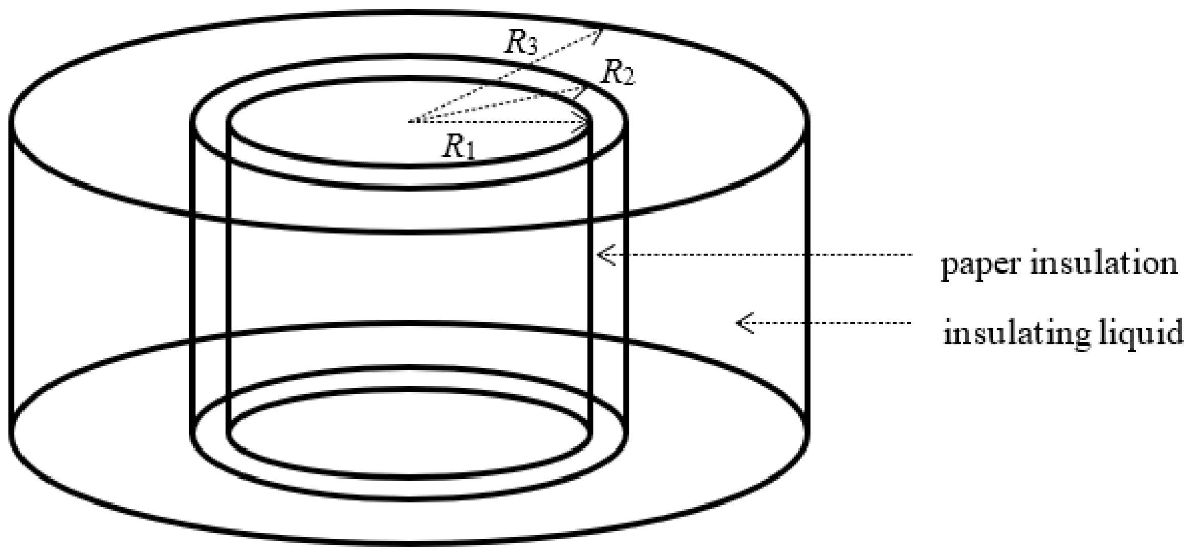
3.3. Determination of Dielectric Losses

Based on the selection of the component values of dielectric losses, performed in Section 3.2, it was found that the pulsation ω has the same value in the entire volume of transformer insulation. A simplifying assumption has been made that the values of electrical permittivity εpaper and εoil are also the same, but, respectively, in the entire volume of paper insulation and in the electrical insulating liquid. The same assumption applies to the dielectric loss coefficient tan(delta) of both insulating materials. The electric field stress E depends on the radius r and on the electrical permittivity of the insulating material, as illustrated in Figure 2. Dielectric losses ΔPdiel will consist of two parts: Losses in paper insulation and losses in the electrical insulating liquid.
After transforming Equation (5), an expression describing dielectric losses in the transformer was obtained:
Δ P diel = V paper Δ p paper drd φ dz + V oil Δ p oil drd φ dz
where Vpaper is the paper insulation volume, Δppaper is the unit dielectric losses in paper insulation, Voil is the volume of electrical insulating liquid, and Δpoil is the unit dielectric losses in the electrical insulating liquid. After substituting Equation (6) into Equation (10), the following expression was obtained:
Δ P diel = V paper E paper 2 · ω · ε paper · tan ( delta ) paper drd φ dz + V oil E oil 2 · ω · ε oil · tan ( delta ) oil drd φ dz
After substituting the relationships describing the electric field stress, (8) and (9), into Equation (11), the following Equation was obtained:
Δ P diel = V paper U 2 r 2 · ε paper 2 · ( ln ( R 2 R 1 ) ε paper + ln ( R 3 R 2 ) ε oil ) 2 · ω · ε paper · tan ( delta ) paper drd φ dz + V oil U 2 r 2 · ε oil 2 · ( ln ( R 2 R 1 ) ε paper + ln ( R 3 R 2 ) ε oil ) 2 · ω · ε oil · tan ( delta ) oil drd φ dz
The integration of the right side of Equation (12) in the V region described in the cylindrical coordinates r ϵ (R1,R2), φ ϵ (0,2π), z ϵ (0,H) in the case of paper insulation (r ϵ (R2,R3), the others as above—electrical insulating liquid) led to a Equation describing the dielectric losses:
Δ P diel = ( R 2 R 1 R 1 · R 2 ) · U 2 · ω · tan ( delta ) paper · 2 · π · H ε paper · ( ln ( R 2 R 1 ) ε paper + ln ( R 3 R 2 ) ε oil ) 2 + ( R 3 R 2 R 2 · R 3 ) · U 2 · ω · tan ( delta ) oil · 2 · π · H ε oil · ( ln ( R 2 R 1 ) ε paper + ln ( R 3 R 2 ) ε oil ) 2
After substituting the relevant data into Equation (13), the value of dielectric losses in paper insulation and the electrical insulating liquid ΔPdiel was obtained. Dielectric losses were estimated on the basis of technical data of 220/110 kV transformers (see Table 2). A voltage value U of 220 kV was assumed. The radius R1 was equal to 0.70 m, which more or less corresponds to the radius of the core with windings. The radius R2 was equal to 0.75 m, which corresponds to the volume of paper insulation (about 2.1 m3). The radius R3 was equal to 1.50 m, which coincides with the actual width of the transformer (about 3 m). Such data correspond to a volume of electrical insulating liquid equal to about 47.7 m3. The ratio of the volume of paper insulation to the volume of liquid was 0.043 (4.3%). The accepted volumes of paper insulation and the electrical insulating liquid and the ratio of these volumes are typical for 220/110 kV transformers [41]. Paper insulation with a volume of 2.1 m3 represented all types of solid insulation in the transformer, and therefore both the winding insulation and main insulation. The highest value of the electric field stress E in paper insulation (for R1) with the accepted data was equal to 2.25 kV∙cm−1, and in the electrical insulating liquid (for R2) it was 4.00 kV∙cm−1, as illustrated in Figure 2. These are typical stress values found in power transformers. A height H equal to 9 m was assumed, which corresponds to three times the height of the transformer (the height of the transformer equal to 3 m × 3 phases).
The results of the estimated calculations were as follows: Losses in paper insulation ΔPpaper amounted to 82 W, and losses in the electrical insulating liquid ΔPoil were 219 W. The value of dielectric losses in the insulation of the transformer ΔPdiel was, therefore, equal to 301 W.

4. Results and Discussion

4.1. Comparison of Polarization Losses with Total Losses of the Transformer

This subsection compares dielectric losses with losses in the windings and transformer core. Dielectric losses (301 W) were determined on the basis of estimated calculations made in earlier subsections. Total losses (in the windings and core) were estimated in two ways.
The first way is to use the data on the transformer’s nameplate. Based on many years of experience gained during diagnostics tests on dozens of transformers, the author assumed a value equal to 200 kW. Dielectric losses were found to account for approximately 0.15% of the total losses.
The second way is to determine the total losses using the same transformer model that was used to calculate the dielectric losses (Figure 1). The side area S of the core with windings, with a radius R1 of 0.70 m and a height H of 9 m, is 39.6 m2. A heat flux density on the surface S (surface heat load) of 2500 W∙m−2 was assumed [17]. This means that the total losses are equal to about 98.91 kW. Thus, dielectric losses ΔPdiel account for 0.30% of total losses. It should be noted that the surface of the windings in a real transformer is much larger and does not correspond to the side surface of the cylinder with the radius R1. This means that the total losses significantly exceed the calculated value of 98.91 kW. Thus, the value of dielectric losses ΔPdiel is much less than 0.30% of the total losses and is closer to 0.15%.

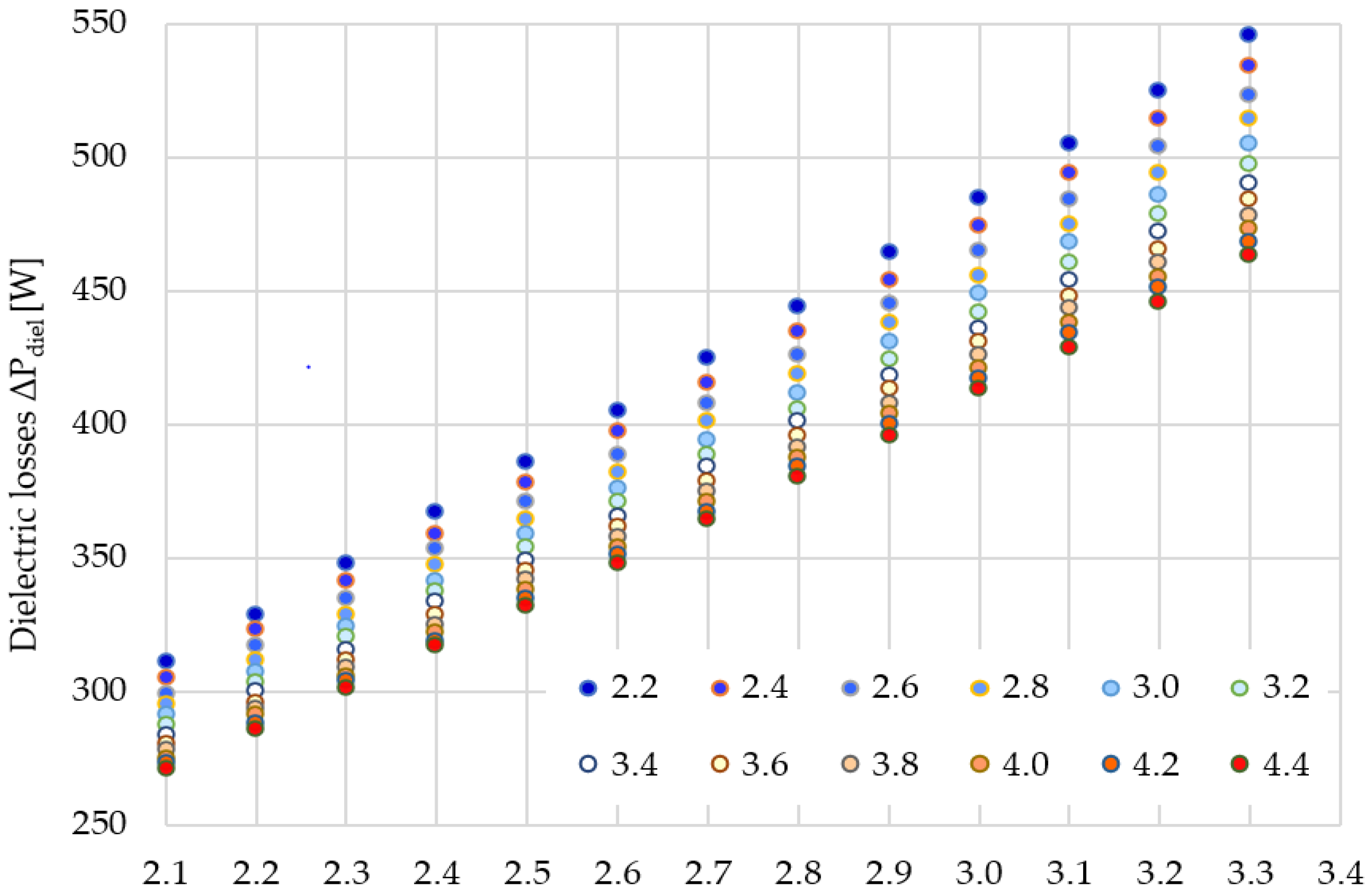
4.2. The Influence of Electrical Permittivity of Paper and Electrical Insulating Liquid on Dielectric Losses in the Transformer

The electrical permittivity of insulating materials, used as transformer insulation, has an indirect effect on the value of dielectric losses. This permittivity, according to Equation (11), determines only the distribution of the electric field stress E in paper and oil. Table 3 shows the ranges of relative electrical permittivity of the most commonly used paper (cellulose, aramid) and electrical insulating liquid (mineral oil, synthetic ester, natural ester). These ranges were used to analyze the effect of permittivity on dielectric losses.
Table 4 and Figure 3 show the value of dielectric losses in the selected transformer depending on the permittivity of the paper and electrical insulating liquid used. The range of electrical permittivity of the paper was 2.2 to 4.4. In contrast, the permittivity range of the liquid was 2.1 to 3.3. The ranges of electrical permittivity were selected on the basis of the data provided in Table 2. As you can see, with an increase in the electrical permittivity of the paper, for a constant value of the permittivity of the electrical insulating liquid, the dielectric losses decrease. However, with an increase in the electrical permittivity of the electrical insulating liquid, the dielectric losses in the transformer increase, for a constant value of the permittivity of the paper. The most favorable case occurred for the lowest value of liquid permittivity and the highest permittivity of paper—271 W. The least favorable case occurred for the lowest permittivity of paper and the highest permittivity of liquids—546 W.
An increase in the electrical permittivity of paper insulation, with a constant value of the permittivity of the liquid, causes a decrease in the electric field stress in paper insulation and an increase in the intensity in the liquid. This is a typical situation for insulating systems stratified in series, consisting of materials with different electrical permittivity. As mentioned, in this case, the dielectric losses decrease. This is due to the fact that the decrease in the electric field stress in the paper is much greater than the increase in the intensity in the electrical insulating liquid.
A similar situation occurs when the electrical permittivity of liquid increases, with a constant permittivity of the paper. Then, the electric field stress in the paper increases, and the intensity in the liquid decreases. The increase in intensity in the paper is much greater than the decrease in intensity in the liquid. As a consequence, the dielectric losses in the transformer increase significantly.
The influence of the electrical permittivity of individual insulation materials on the value of dielectric losses in the transformer is not unambiguous. This effect should be related to the electric field stress in the individual insulation materials. Based on the calculations carried out, it can be concluded that the electrical permittivity of paper insulation, relative to the electrical permittivity of the liquid, has a key impact on the value of dielectric losses. The greater the permittivity of paper insulation, the lower the electric field stress in the paper, which affects the decrease in dielectric losses throughout the transformer.

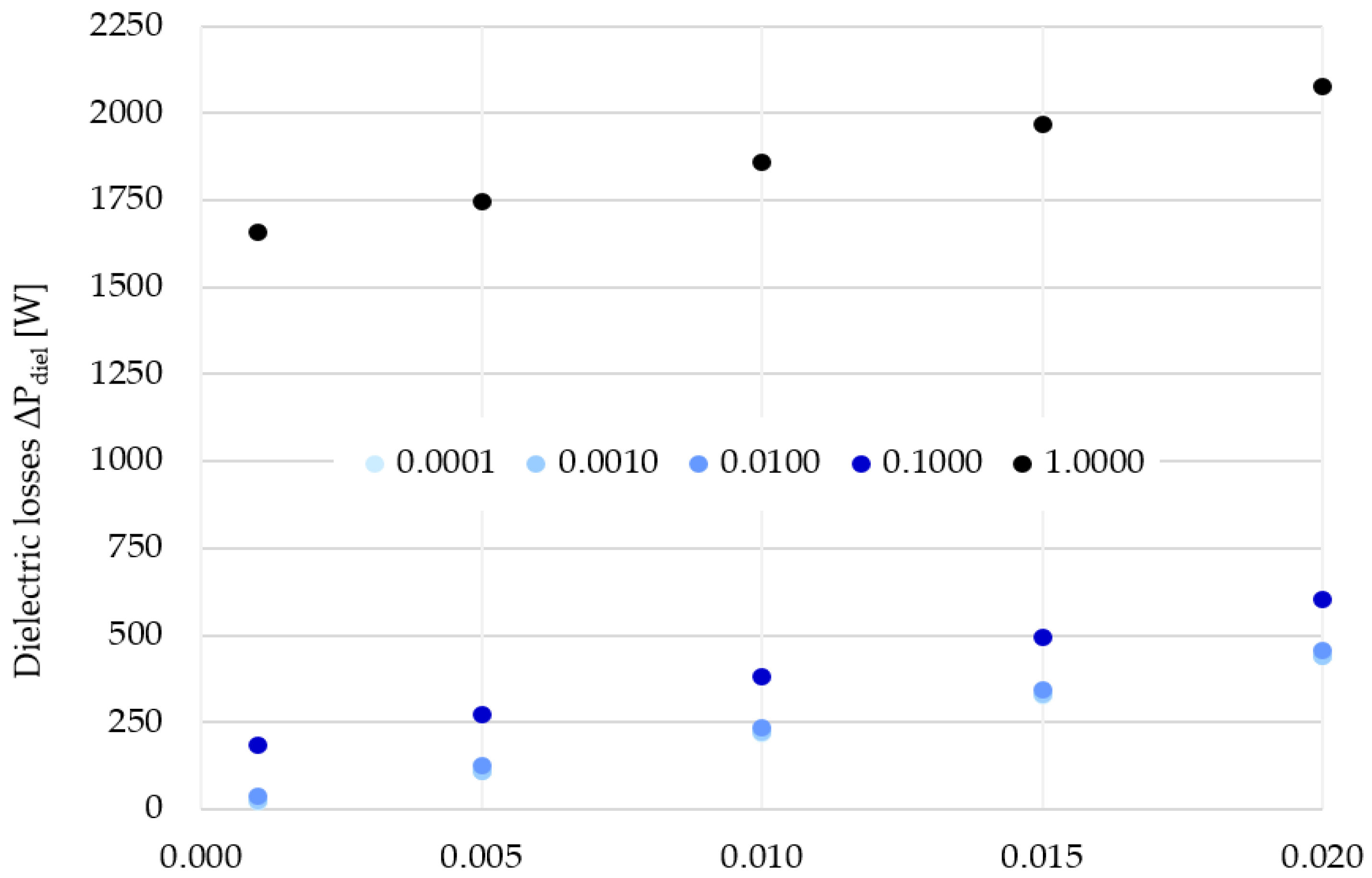
4.3. The Influence of the Dielectric Loss Coefficient tan(delta) of Paper Insulation and Electrical Insulating Liquid on Dielectric Losses in the Transformer

The influence of the coefficient of dielectric losses tan(delta) of both paper insulation and electrical insulating liquid on dielectric losses in the transformer is unambiguous, which results from Equation (4). An increase in the tan(delta) coefficient of both electrical insulating materials results in an increase in dielectric losses.
Table 5 and Figure 4 show the values of dielectric losses in the selected transformer depending on the tan(delta) coefficient of paper and liquid. The range of the values of the tan(delta) coefficient of the paper can be very wide. It depends mainly on the technical condition of the paper (mainly dampness) and the degree of its aging [42,43]. For this reason, the range of the tan(delta) coefficient of the paper, taken for the calculation of losses, was 0.0001 to 1.0000. On the other hand, the range of values of the dielectric loss coefficient of the insulating liquid is already much smaller. The range adopted for the calculation was 0.001 to 0.020.
As might be expected, as the dielectric loss coefficient of both insulating materials increases, the dielectric losses in the transformer increase, too. The smallest losses (22 W) were determined for the smallest values of the dielectric loss coefficient of the paper and liquid. In turn, the largest dielectric losses (2076 W) occurred for the largest values of the tan(delta) coefficient of the paper and liquid. As we can see, the coefficient of dielectric losses tan(delta) of the paper and electrical insulating liquid has a significant impact on the value of dielectric losses. These losses can increase from a dozen watts to several thousand watts.

5. Conclusions

The determined dielectric losses in the case of the analyzed and studied transformer, for typical values of electrical permittivity and the dielectric loss coefficient, were 82 W (losses in paper insulation) and 219 W (losses in electrical insulating liquid). As you can see, most of the dielectric losses occurred in the electrical insulating liquid, which is due to the larger volume of the liquid compared to the volume of paper insulation. In total, the value of dielectric losses was equal to 301 W.
The value of dielectric losses is a fraction of a percent of total losses. Regardless of how total losses are determined, the value of dielectric losses ranges from 0.15% to 0.30%.
The electrical permittivity of paper insulation and the electrical insulating liquid has an ambiguous effect on the value of dielectric losses in the transformer. This effect should be related to the electric field stress in individual insulating materials, which depends on the ratio of electrical permittivity of these materials. The electrical permittivity of paper insulation has a key impact on the value of dielectric losses. With the increase in the electrical permittivity of paper insulation, the electric field stress in this insulation decreases, which results in a decrease in dielectric losses throughout the transformer.
The dielectric loss coefficient tan(delta) has a significant impact on the dielectric losses in the transformer. An increase in the tan(delta) coefficient of both paper insulation and the electrical insulating liquid causes an increase in dielectric losses. Dielectric losses can increase by up to two orders of magnitude.

Funding

The research was financed by the Poznan University of Technology’s financial resources for statutory activity. The number of projects: 0711/SBAD/4514.

Institutional Review Board Statement

Not applicable.

Informed Consent Statement

Not applicable.

Data Availability Statement

Not applicable.

Conflicts of Interest

The author declares no conflict of interest.

References

  1. Gao, R.; Guo, H.; Zhang, R.; Mao, T. A two-stage dispatch mechanism for virtual power plant. Utilizing the CVaR theory in the electricity spot market. Energies 2019, 12, 3402. [Google Scholar] [CrossRef] [Green Version]
  2. Lu, T.; Zhang, W.; Ding, X. Operation strategy of electricity retailers based on energy storage system to improve comprehensive profitability in China’s electricity spot market. Energies 2021, 14, 6424. [Google Scholar] [CrossRef]
  3. Bonfiglio, A.; Brignone, M.; Invernizzi, M.; Labella, A.; Mestriner, D.; Procopio, R. A simplified microgrid model for the validation of islanded control logics. Energies 2017, 10, 1141. [Google Scholar] [CrossRef] [Green Version]
  4. Cuadra, L.; Del Pino, M.; Nieto-Borge, J.C.; Salcedo-Sanz, S. Optimizing the structure of distribution smart grids with renewable generation against abnormal conditions: A complex networks approach with evolutionary algorithms. Energies 2017, 10, 1097. [Google Scholar] [CrossRef] [Green Version]
  5. Gong, R.; Ruan, J.; Chen, J.; Quan, Y.; Wang, J.; Duan, C. Analysis and experiment of hot-spot temperature rise of 110 kV Three-phase three-limb transformer. Energies 2017, 10, 1079. [Google Scholar] [CrossRef] [Green Version]
  6. Constantin, A.; Löwen, A.; Ponci, F.; Müller, D.; Monti, A. Design, implementation and demonstration of embedded agents for energy management in non-residential buildings. Energies 2017, 10, 1106. [Google Scholar] [CrossRef] [Green Version]
  7. Prasojo, R.A.; Suwarno, K.D.; Gumilang, H. Transformer paper expected life estimation using anfis based on oil characteristics and dissolved gases (case study: Indonesian transformers). Energies 2017, 10, 1135. [Google Scholar] [CrossRef] [Green Version]
  8. Fonseca, M.; Bezerra, U.H.; Leite, J.C.; Rodríguez, J.L.M. Maintenance tools applied to electric generators to improve energy efficiency and power quality of thermoelectric power plants. Energies 2017, 10, 1091. [Google Scholar]
  9. Havran, P.; Cimbala, R.; Kurimský, J.; Dolník, B.; Kolcunová, I.; Medveď, D.; Király, J.; Kohan, V.; Šárpataky, L. Dielectric properties of electrical insulating liquids for high voltage electric devices in a time-varying electric field. Energies 2022, 15, 391. [Google Scholar] [CrossRef]
  10. Linde, T.; Ting Loh, J.; Kornhuber, S.; Backhaus, K.; Schlegel, S.; Großmann, S. Implications of nonlinear material parameters on the dielectric loss under harmonic distorted voltages. Energies 2021, 14, 663. [Google Scholar] [CrossRef]
  11. Charalampakos, V.P.; Peppas, G.D.; Pyrgioti, E.C.; Bakandritsos, A.; Polykrati, A.D.; Gonos, I.F. Dielectric insulation characteristics of natural ester fluid modified by colloidal iron oxide ions and silica nanoparticles. Energies 2019, 12, 3259. [Google Scholar] [CrossRef] [Green Version]
  12. David, C.; Koduvelikulathu, L.J.; Kopecek, R. Comparative simulations of conductive nitrides as alternative plasmonic nanostructures for solar cells. Energies 2021, 14, 4236. [Google Scholar] [CrossRef]
  13. Szczegielniak, T.; Kusiak, D.; Jabłoński, P. Thermal analysis of the medium voltage cable. Energies 2021, 14, 4164. [Google Scholar] [CrossRef]
  14. Diban, B.; Mazzanti, G. The effect of insulation characteristics on thermal instability in HVDC extruded cables. Energies 2021, 14, 550. [Google Scholar] [CrossRef]
  15. Uydur, C.C.; Arikan, O. Use of tanδ and partial discharge for evaluating the cable termination assembly. Energies 2020, 13, 5299. [Google Scholar] [CrossRef]
  16. Ludowicz, W.; Wojciechowski, R.M. Analysis of the distributions of displacement and eddy currents in the ferrite core of an electromagnetic transducer using the 2D approach of the edge element method and the harmonic balance method. Energies 2021, 14, 3980. [Google Scholar] [CrossRef]
  17. Cao, M.; Chen, Y.; Ma, C.; Liu, Q. Design and research of a three-phase AC magnetic separator for coal desulfurization and ash reduction. Appl. Sci. 2020, 10, 2871. [Google Scholar] [CrossRef] [Green Version]
  18. Jezierski, E. Construction and Calculation of Cores of Power Transformers; Scientific-Technical Publisher: Warsaw, Poland, 1979. [Google Scholar]
  19. Crisan, O.; Dan, I.; Palade, P.; Crisan, A.D.; Leca, A.; Pantelica, A. Magnetic phase coexistence and hard–soft exchange coupling in FePt nanocomposite magnets. Nanomaterials 2020, 10, 1618. [Google Scholar] [CrossRef] [PubMed]
  20. Gamil, A.; Schatzl, F. In Determining of Transformers Core Losses Based o Investigation of Core-Sheet Behavior during Power Transformer Test and Operation. In Proceedings of the International Conference Transformer’13, Gdansk, Poland, 5–7 June 2013. [Google Scholar]
  21. Vergallo, C.; Dini, L. Comparative analysis of biological effects induced on different cell types by magnetic fields with magnetic flux densities in the range of 1–60 mT and frequencies up to 50 Hz. Sustainability 2018, 10, 2776. [Google Scholar] [CrossRef] [Green Version]
  22. Kanwal, S.; Wen, J.; Yu, B.; Chen, X.; Kumar, D.; Kang, Y.; Bai, C.; Ubaid, S.; Zhang, D. Polarization insensitive, broadband, near diffraction-limited metalens in ultraviolet region. Nanomaterials 2020, 10, 1439. [Google Scholar] [CrossRef]
  23. Beroual, A.; Haddad, A. Recent advances in the quest for a new insulation gas with a low impact on the environment to replace sulfur hexafluoride (SF6) gas in high-voltage power network applications. Energies 2017, 10, 1216. [Google Scholar] [CrossRef] [Green Version]
  24. Nadolny, Z.; Braun, J.M. In Investigation of Partial Discharge Pulse Shapes Occurring within Model XLPE Transmission Cable Joint. In Proceedings of the VI International Conference on Conduction and Breakdown in Solid Dielectrics, Vasteras, Sweden, 22–25 June 1998. [Google Scholar]
  25. Nadolny, Z.; Braun, J.M. In Influence of Contaminants on Partial Discharge Characteristics for Model XLPE Transmission Cable Joints. In Proceedings of the International Symposium on Electrical Insulation, Arlington, VA, USA, 7–10 June 1998. [Google Scholar]
  26. Densley, J.; Kalicki, T.; Nodolny, Z. Characteristics of PD pulses in electrical trees and interfaces in extruded cables. IEEE Trans. Dielectr. Electr. Insul. 2001, 8, 48–57. [Google Scholar] [CrossRef]
  27. Choi, H.; Koo, J.B.; Son, J.A.; Yi, J.S.; Yoon, Y.G.; Oh, T.K. Development of equipment and application of machine learning techniques using frequency response data for cap damage detection of porcelain insulators. Appl. Sci. 2020, 10, 2820. [Google Scholar] [CrossRef] [Green Version]
  28. Tang, J.; Yang, X.; Yang, D.; Yao, Q.; Miao, Y.; Zhang, C.; Zeng, F. Using SF6 decomposed component analysis for the diagnosis of partial discharge severity initiated by free metal particle defect. Energies 2017, 10, 1119. [Google Scholar] [CrossRef] [Green Version]
  29. Ho, W.C.; Liu, Y.H.; Wu, W.H.; Chen, H.; Tzou, J.; Kuo, H.C.; Sun, C.W. The study of high breakdown voltage vertical GaN-on-GaN p-i-n diode with modified mesa structure. Crystals 2020, 10, 712. [Google Scholar] [CrossRef]
  30. IEC 60076-7; Power Transformers-Part 7: Loading Guide for Oil—Immersed Power Transformers; IEC: Geneva, Switzerland, 2008; pp. 4–56.
  31. Marek, R.P. Dielectric Comparisons of Different Types of Aramid Insulation. In Proceedings of the 2nd International Colloquium Transformer Research and Asset Management, Dubrovnik, Croatia, 16–18 May 2012. [Google Scholar]
  32. Fofana, I.; Wasserberg, V.; Borsi, H. Challenge of mixed insulating liquids for use in high-voltage transformers, part 2: Investigations of mixed liquid impregnated paper insulation. IEEE Electr. Insul. Mag. 2002, 18, 4. [Google Scholar]
  33. Aruna, M.; Vasudev, N.; Ravi, K.N. Novel Insulation System in Power Transformer. In Proceedings of the 10th International Conference on the Properties and Applications of Dielectric Materials, Bangalore, India, 24–28 July 2012. [Google Scholar]
  34. Shane, C.P. Distribution and power transformers. IEEE Ind. Appl. Mag. 2000. [Google Scholar]
  35. Dua, R.; Bhandari, N.; Kumar, V. Multi-criteria optimization for obtaining efficiently blended transformer oils. IEEE Trans. Dielectr. Electr. Insul. 2008, 15, 879–887. [Google Scholar] [CrossRef]
  36. Li, J.; Liao, R.; Yang, L. Investigation of Natural Ester Based Liquid Dielectrics and Nanofluids. In Proceedings of the International Conference on High Voltage Engineering and Application ICHVE, Shanghai, China, 17–20 September 2012. [Google Scholar]
  37. Aksamit, P.; Zmarzly, D. Dielectric Properties of Fullerene-Doped Insulation Liquids. In Proceedings of the Conference on Electrical Insulation and Dielectric Phenomena, Kansas City, MO, USA, 15 October 2009. [Google Scholar]
  38. Li, J.; Zhang, Z.; Zou, P. Preparation of a vegetable oil-based nanofluids and investigation of its breakdown and dielectric properties. IEEE Electr. Insul. Mag. 2012, 28, 43–50. [Google Scholar] [CrossRef]
  39. Perrier, C.; Beroual, A. Experimental Investigations on Insulating Liquids for Power Transformers: Mineral, Ester, and Silicone Oils. IEEE Electr. Insul. Mag. 2009, 25, 6–13. [Google Scholar] [CrossRef]
  40. Rozga, P.; Skowron, A. Changing the Dielectric Dissipation Factor of Transformer Fluid based on Synthetic Ester in the Condition of a Concentrated Heat Flux. In Proceedings of the International Conference on High Voltage Engineering and Application ICHVE, Shanghai, China, 17–20 September 2012. [Google Scholar]
  41. Moscicka-Grzesiak, H. Moisture of Cellulose Insulation in Numbers in Terms of Physical Phenomena and Operational Consequences. In Proceedings of the International Conference Transformer’11, Torun, Poland, 1–3 June 2011. [Google Scholar]
  42. Makmud, M.Z.H.; Illias, H.A.; Chee, C.Y.; Dabbak, S.Z.A. Partial discharge in nanofluid insulation material with conductive and semiconductive nanoparticles. Materials 2019, 12, 816. [Google Scholar] [CrossRef] [PubMed] [Green Version]
  43. Nissilä, T.; Wei, J.; Geng, S.; Teleman, A.; Oksman, K. Ice-templated cellulose nanofiber filaments as a reinforcement material in epoxy composites. Nanomaterials 2021, 11, 490. [Google Scholar] [CrossRef] [PubMed]
Figure 1. Transformer insulation model, R1—cylinder radius reflecting windings and core, R2 − R1 = paper insulation thickness, R3 − R2 = space filled with electrical insulating liquid.
Energies 15 00993 g001
Figure 2. Electric field stress E inside the transformer insulation between the winding and the tank (paper insulation: 0.70 ÷ 0.75 m, electrical insulating liquid: 0.75 ÷ 1.50 m, U = 220 kV).
Energies 15 00993 g002
Figure 3. Dielectric losses in the selected transformer depending on the electrical permittivity of used paper and the electrical insulating liquid (legend corresponds to relative electrical permittivity of the paper).
Energies 15 00993 g003
Figure 4. Dielectric losses in the selected transformer depending on the dielectric loss coefficient tan(delta) of the paper and the electrical insulating liquid (legend corresponds to the dielectric loss coefficient tan(delta) of the paper).
Energies 15 00993 g004
Table 1. Values of the components in Equation (6) used to calculate the dielectric losses.
ParameterUnitValue
frequency entry 1Hz50
pulsations−1314.2
relative electrical permittivity of paper εr.paper-4.4
paper dielectric loss coefficient tan(delta)paper-0.05
relative electrical permittivity of oil εr.oil-2.3
oil dielectric loss coefficient tan(delta)oil-0.01
Table 2. Technical data of selected 220/110 kV transformers used to estimate dielectric losses [41].
ParameterUnitValue
voltagekV220
radius R1, corresponding to the core radiusm0.70
radius R2, corresponding to the core radius with paper insulationm0.75
volume of paper insulationm32.1
radius R3, corresponding to the width of transformerm1.50
volume of electrical insulating liquidm347.7
ratio of the volume of paper insulation to the volume of liquid%4.3
highest value of the electric field stress E in paper insulationkV∙cm−12.25
highest value of the electric field stress E in electrical insulation liquidkV∙cm−14.00
height of the transformer (3 × 3 phases)m9
Table 3. Relative electrical permittivity of insulating materials used in power transformer, for T = 25 °C [30,31,32,33,34,35,36,37,38,39,40].
MaterialValue
impregnated cellulose paper2.2 ÷ 4.4
impregnated aramid paper2.9 ÷ 3.8
mineral oil2.1 ÷ 2.3
synthetic esters3.2 ÷ 3.3
natural ester2.9 ÷ 3.3
Table 4. Dielectric losses in the selected transformer depending on the electrical permittivity of paper and the electrical insulating liquid used.
Dielectric Losses [W]Relative Electrical Permittivity of Paper
2.22.42.62.83.03.23.43.63.84.04.24.4
Relative electrical permittivity of electrical insulating liquid2.1311305299295291287283280278275273271
2.2329323317312307303300296293291288286
2.3348341335329324320316312309306304301
2.4367359353347341337333329325322319317
2.5386378371364359354349345342338335332
2.6405397389382376371366362358354351348
2.7425416408401394389384379375371367364
2.8444435426419412406401396391387384380
2.9464454445438431424418413408404400396
3.0485474465456449442436431426421417413
3.1505494484475468460454448443438434429
3.2525514504494486479472466460455451446
3.3546534523514505497490484478473468463
Table 5. Dielectric losses in the selected transformer depending on the dielectric loss coefficient tan(delta) of the paper and the electrical insulating liquid.
Dielectric Losses
ΔPdiel [W]
Dielectric Loss Coefficient
tan(delta) of Paper
0.00010.00100.01000.10001.0000
Dielectric loss
coefficient tan(delta)
of the electrical
insulating liquid
0.0012224381861 660
0.0051101111262731 747
0.0102192212363831 857
0.0153293313454931 967
0.0204394404556022 076
Publisher’s Note: MDPI stays neutral with regard to jurisdictional claims in published maps and institutional affiliations.

