Abstract
A grid-connected inverter’s stability is easily influenced by the system’s internal and external characteristics, especially when the grid-connected inverter is connected to the grid by an LCL filter, which complicates the system design and operating conditions. To handle the problem of disturbance in the high-order grid-connected system of the inverter, a linear active disturbance rejection control (LADRC) strategy based on LCCL (which divides the capacitor of the LCL filter into two halves in a specified proportion) is proposed in this paper. First, the system is reduced from third order to first order by using the split capacitor control method, which solves the difficulties of complicated LCL grid-connected inverter controller design and easy resonance. Meanwhile, the internal and external disturbances of the inverter system are treated as generalized disturbances. Then, the LADRC control is used to adjust the closed-loop system’s parameters, which enhances the quality of the grid current and the system’s stability. Finally, the impacts of PI and LADRC control on the power mutation and voltage drop of an LCCL grid-connected inverter are compared by the experiments. The experimental results show the effectiveness of the proposed LADRC control strategy.
1. Introduction
With the rapid development of new energy microgrids, more and more attention has been paid to the technical research of distributed generation [1]; renewable energy (such as wind energy, solar energy, etc.) usually uses LCL filters as the interface be-tween the inverter and the grid [2,3]. The third-order characteristics of LCL filter make the controller design more complex and prone to resonance [4]. Inverter grid-connected current control is divided into inverter side current control and grid side current control. When the inverter side current control is used, the filter capacitor needs to consume reactive power, so the capacitor value is not easy to be too large, otherwise it will reduce the power factor of grid-connected [5]. The stability of the control system is poor when the grid side current control is adopted [6]. Reference [7] adds passive damping at the filter capacitance, which makes the dynamic response of the system slower and the bandwidth smaller. Reference [8] adopts the full feedforward control of the grid voltage to improve the dynamic characteristics of the system. Reference [9] uses the sliding mode control of variable structure control to improve the robustness of the system, but its inherent chattering characteristic affects the control accuracy. References [10,11] proposes a control strategy based on split capacitor current feedback to simplify the parameter setting of the control system, but it cannot suppress the fluctuations of the inductance and capacitance on the grid side of the system, causing the grid current to resonate and the current THD to increase.
The ADRC does not depend on the system model, but on the basic properties of the system order [12,13]. In order to simplify the design process of ADRC controller parameters, the bandwidth method is usually used to normalize the parameters of multiple ADRC controllers [14,15]. An extended state observer (ESO) can track generalized disturbances (external and internal) in time [16,17,18]. Reference [19] is a first-order ADRC controller based on a single-inductor filter design, which solves the problem between system overshoot and system rapidity. Reference [20] studied the nonlinear ADRC controller of grid-connected inverter with LCL filter, but the design process is complicated. Reference [21] established a low-order approximation model of LCL filter through Pade approximation, but did not provide stability performance analysis. Reference [22] designed a third-order ADRC controller for LCL grid-connected inverters combined with active damping, which improved the quality of the grid-connected current, but increased the complexity of the control algorithm. Reference [23] proposed an ESO-based LCL grid-connected inverter current control to improve system stability by separating the traditional coupled observer disturbance and model error, but ADRC was used for disturbance compensation.
The main contributions of this paper are summarized as follows.
- (1)
- This research offers an ADRC current control approach for grid-connected inverters based on LCCL to address the aforementioned issues. The combination of LCCL and passive dampening can efficiently suppress grid side current oscillation.
- (2)
- The basic principle of first-order LADRC is investigated, and LADRC control is applied to the control strategy of an LCCL grid-connected inverter.
- (3)
- By comparing PI control and LADRC control, a simulation and experimental platform is constructed to control the LCCL grid-connected inverter. The effectiveness of LADRC’s system control is verified.
2. LCCL Grid-Connected Inverter Topology Structure
Figure 1 is the topology of three-phase split capacitor LCL grid-connected inverter (split capacitor is the form of splitting the filter capacitor C into two capacitors and in parallel, so it can also be called LCCL grid-connected inverter). are 6 inverter switches; is the DC side supporting capacitor; is the x-phase inductance of the inverter side, is the x-phase inductance of the grid side, is the phase filter capacitor; is the DC bus voltage; is the Point of Common Coupling (PCC) voltage of the x-phase. is the grid voltage; is the inverter side current of x-phase, is the current between the split capacitors of x-phase, is the grid-side current of x-phase, is the grid-connected current of x-phase, and . are d, q axis components of in dq coordinate system; are d, q axis components of in dq coordinate system. is the a, b, c axis components of in abc coordinates respectively; is the phase information of the grid voltage obtained by the Phase Locked Loop (PLL). are the reference current values in the dq coordinate system.
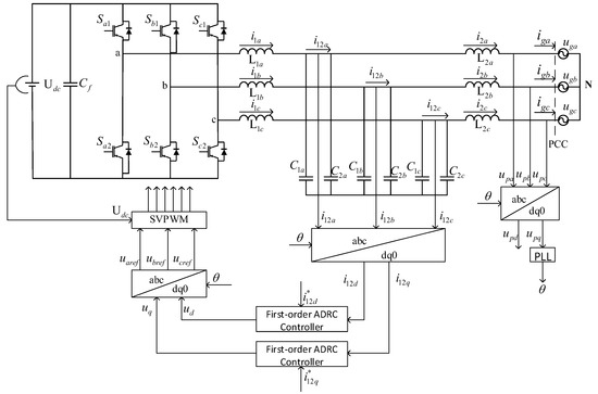
Figure 1.
Three-phase LCCL grid-connected inverter.
Aiming at the establishment of the mathematical model of the split capacitor LCL three-phase grid-connected inverter, the following assumptions are made:
- (1)
- The inductance of the filter is linear, and saturation is not considered, and active power loss is ignored;
- (2)
- The DC side voltage is a constant value;
- (3)
- All IGBTs in the main circuit are ideal devices, that is, switching loss and switching time are not considered;
- (4)
- The three-phase grid voltage is symmetrical, that is, ;
- (5)
- The working state of the three-phase is symmetrical, , , , .
In the three phase system,
where, is the voltage between the midpoint of the three-phase bridge arm and the N point; is the capacitor side voltage. From Equation (1), the transfer function between and can be obtained as follows.
When the capacitance of the capacitor satisfies , will reduce to a first-order system.
Equation (3) is the key to implement the current feedback control in the middle of the split-capacitor capacitor, satisfying the zero-pole cancellation to reduce the system to a first-order system. The feedback current is the intermediate current after the LCL filter capacitors are separated. The ratio of the capacitance of the two parts separated into the front and rear is equal to the inverse ratio of the inductance of the two inductors before and after the LCL filter, as shown in Equation (4).
To sum up, the control strategy of the capacitor splitting method is to divide the capacitor of the LCL filter into two parts, the front and the back, respectively with a specific ratio, and use the middle current of the two parts of the capacitor as the current feedback control object for current closed-loop control.
From Equation (3), the state space Equation of the split-capacitor LCL three-phase grid-connected inverter in the dq rotating coordinate system can be obtained after the order reduction is as follows:
where, is the angular frequency of the grid voltage fundamental wave.
3. Current Control Based on LADRC
3.1. Reconstruction of the State Equation
Taking the d-axis as an example, design a first-order LADRC controller. Let be the unknown external disturbance of the system, the differential expression of the system after the order reduction can be obtained from Equation (5).
Since the filter parameters may be perturbed during the operation of the grid-connected system, considering the filter parameter perturbation, the differential expression of the system after the order reduction is as follows:
where, is the actual inductance of inductors and . The first four terms of Equation (7) include external perturbations, as well as internal perturbations caused by coupling and model parameter perturbations. Here, let denote the total disturbance of the system.
Rewrite the differential Equations of the system.
Assuming , ; then the state variable is .The state Equation of the system can be obtained according to Equation (8).
Let , , , ; The state Equation of the system can be rewritten in the form of Equation (11). This Equation is the reconstructed state Equation expression of the first-order grid-connected inverter including the total disturbance.
3.2. Design of LESO
Since is not directly available in practical engineering. Therefore, the LESO in this process can only be constructed using the inputs and outputs in the system. Assume is differentiable with respect to t; is bounded.
Assuming that and are the estimated values of state variables and , respectively. That is, the estimated values of and total disturbance , the corrected LESO state Equation can be obtained.
Let , , then the state Equation of LESO can be expressed in the form of Equation (12).
where, is the observer gain parameter of LESO, which is usually designed as , which is the eigenvalue that satisfies the Hurwitz stability criterion. The observer parameterization method often adopts the method such as Equation (14).
3.3. Design of LSEF
In the framework of LADRC, the main idea is to implement a LESO to provide an estimate , so that can be compensated by suppressing the disturbance, which not only realizes the function of the integral in the PID, but also avoids the negative effects brought by the integral link. The variables estimated from disturbances are used to implement control laws, including disturbance rejection and feedback control laws. Then the control law of the first-order ADRC controller is in the form of Equation (15).
the expression of is shown in Equation (16).
where, is the proportional coefficient, also known as the controller bandwidth; the feedback control law is a proportional controller.
The expression of LADRC is given by Equation (17).
LESO and LSEF constitute a basic first-order LADRC controller as shown in Figure 2, where, is the input disturbance and is the measurement noise disturbance.
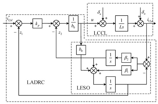
Figure 2.
Grid-connected inverter LADRC block diagram.
To sum up, in order to realize the LADRC current controller of grid-connected inverter based on split capacitor, the following three steps need to be taken:
- (1)
- What you need to know about the inverter is ;
- (2)
- Construct a LESO, providing estimates of the control current and generalized perturbation, and then construct the control law as shown in Equation (17);
- (3)
- The observer bandwidth can be obtained from Equation (14), . The bandwidth of the controller is usually obtained by an empirical formula .
In order to facilitate the analysis of the LCCL grid-connected inverter system controlled by the first-order LADRC, the transfer function of the first-order LADRC system is obtained through the analysis, as shown in Equation (18).
From Equation (18), the block diagram of the first-order LADRC transfer function as shown in Figure 3 can be derived, where represents the plant.
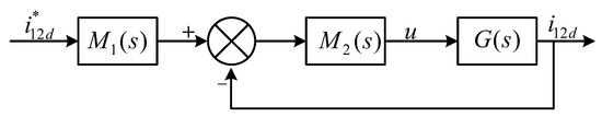
Figure 3.
Block diagram of the first−order LADRC transfer function.
When the first-order LADRC method is adopted, the transfer function is as shown in Equation (18). The control structure diagram of its d-axis is shown in Figure 4.The control method of split capacitor current feedback can make the current between capacitors accurately track the given and does not contain the resonant sub-current, while there is a resonant pole in the closed-loop transfer function expression with as the output, and the resonant sub-current component in the grid-connected current will be large. In order to solve this problem, it can be considered to add a passive damping at the second capacitor , which can effectively suppress the resonance in the grid-connected current.
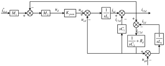
Figure 4.
D-axis structure diagram of split capacitor control system.
4. Analysis of System Performance
The first-order LESO is the core of the first-order ADRC system, which not only provides the feedback current, but also provides a real-time estimation of the generalized disturbance of the system. The performance of the first-order LESO will affect the effectiveness of the first-order LADRC. Let the observation error of LESO, then the Equation as shown in Equation (19) can be obtained.
Subtracting Equation (12) from Equation (11) yields the Equation shown in Equation (20).
Laplace transform of Equation (20), we can get Equation (21),
The inherent relationship between and can be derived from Equation (21), and the transfer function between them is shown in Equation (22).
Let rad/s, it can be seen from Figure 5 that when the disturbance is composed of low-frequency signals, can track disturbance well. Furthermore, as increases, the estimation error will decrease.
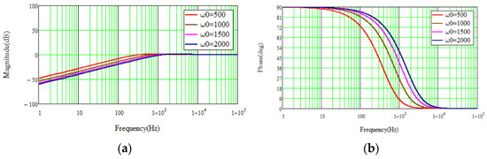
Figure 5.
The magnitude and phase frequency curves of . (a) Magnitude. (b) Phase.
From Equations (10) and (11), the generalized perturbation can be obtained as shown in Equation (23).
Laplace transform of Equation (28) into the s-domain,
substituting Equation (24) into Equation (21), the state error estimate for LESO can be obtained as shown in Equation (25).
Combining Equations (25) and (19), the state variables in the s domain can be obtained.
Therefore, the transfer functions of the estimated state variable generated by the measurement noise and the input disturbance , respectively, can be obtained as shown in Equations (27) and (28).
Let ; the magnitude and phase frequency curves of Equations (27) and (28) can be obtained as shown in Figure 6 and Figure 7, respectively.
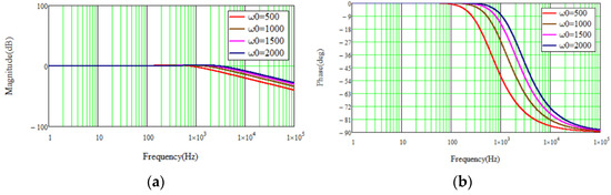
Figure 6.
The magnitude and phase frequency curves of . (a) Magnitude. (b) Phase.
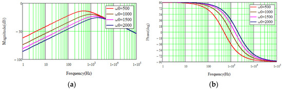
Figure 7.
The magnitude and phase frequency curves of . (a) Magnitude. (b) Phase.
As can be seen from Figure 6, an increase in increases the high frequency gain, that is, when increases, the LESO becomes more sensitive to measurement noise. As can be seen from Figure 7, as increases, the phase lag of can be reduced, but it has no effect on the high-frequency gain, which shows that LESO can attenuate the input disturbance in the low-frequency region. Therefore, there is a trade-off between input disturbance rejection and measurement noise sensitivity when choosing the bandwidth of the LESO.
5. System Simulation and Experiment
The first-order ADRC-controlled LCCL system shown in Figure 1 is built on the simulation and experimental platforms, respectively. The specific parameters are shown in Table 1.

Table 1.
System parameters.
According to the system parameter values in Table 1, the effectiveness of the system proposed in this paper is verified under different control methods and different working conditions.
5.1. System Simulation
5.1.1. Power Mutation
In different control modes, when the system reference current . When is changed from 30 A to 50 A, the waveform of the grid-connected current and the THD analysis before and after the current abrupt change are shown in Figure 8.
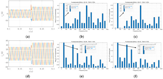
Figure 8.
Comparison of grid current for PI control and LADRC control. (a) Grid current waveform diagram of PI Control. (b) THD diagram without current mutation of PI Control. (c) THD diagram with current mutation of PI Control. (d) Grid current waveform diagram of LADRC Control. (e) THD diagram without current mutation of LADRC Control. (f) THD diagram with current mutation of LADRC Control.
Comparing Figure 8, it can be seen that when the grid-connected system adopts the first-order LADRC, the grid-connected current has no overshoot at a given sudden change, and can track the reference faster, and the adjustment time of the system is shorter. Comparison of THD without and with current mutation. It can be seen that compared with the PI control mentioned in Reference [11], the first-order LADRC can make the grid current have better current quality and higher tracking accuracy.
5.1.2. Grid Voltage Drop
Figure 9 show the grid voltage and grid current when the grid voltage instantly drops by 50% of the rated value under different control methods. Comparing Figure 9, it can be seen that at the moment of grid voltage drop, the system using the first-order LADRC has higher stability and stronger dynamic noise immunity.
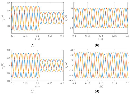
Figure 9.
Grid voltage and grid current when grid voltage drops under PI control and LADRC control. (a) Grid voltage with PI control; (b) grid current with PI control;(c) grid voltage with ADRC control; (d) grid current with ADRC control.
5.1.3. Passive Damping
Under the first-order LADRC, by comparing whether passive damping is added to the second capacitor of the split capacitor, it is shown that adding passive damping can reduce the resonance of the incoming current. Figure 10 shows the simulation results without passive damping, and the simulation results with passive damping.
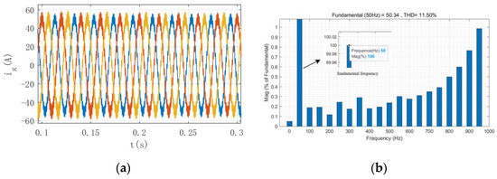
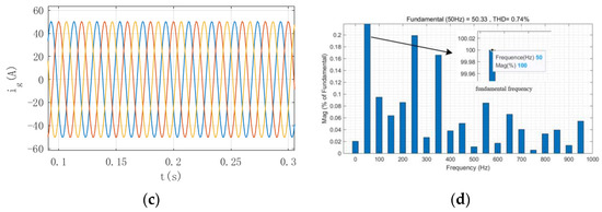
Figure 10.
Grid current without passive damping and with passive damping. (a) Current without passive damping; (b) THD diagram without passive damping; (c) Current with passive damping; (d) THD diagram with passive damping.
After adding passive damping on branch , compared with Figure 10, it can be seen that after adding passive damping, the resonant current content in the grid current decreases and the THD decreases to the specified range. By comparison, it can be known that and will resonate when using split capacitor control, resulting in a large harmonic content in the grid current. After adding passive damping, the oscillation of the grid current can be well suppressed, and the THD range is within a reasonable range, so that the grid current can meet the requirements.
5.2. Experiment Verification
The experimental platform shown in Figure 11 is established to verify the effectiveness of the control method proposed in this paper. This experiment uses Yuankuan Energy StarSim HIL system to verify the system. The real-time simulator forms a closed loop with the control board under test through IO signals or communication to test the weak current control board (usually the DSP board).
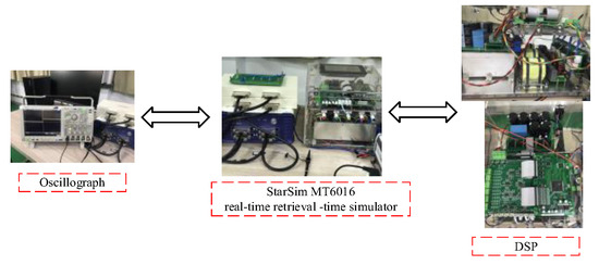
Figure 11.
System Physical Diagram.
Figure 12 shows the grid-side current waveform under the first-order LADR control. It can be seen from the Figure that when the reference current , changes from 50 A to 100 A in the vicinity of 0.5 s, the first-order LADRC control system can make the incoming current have good current quality and high control accuracy.
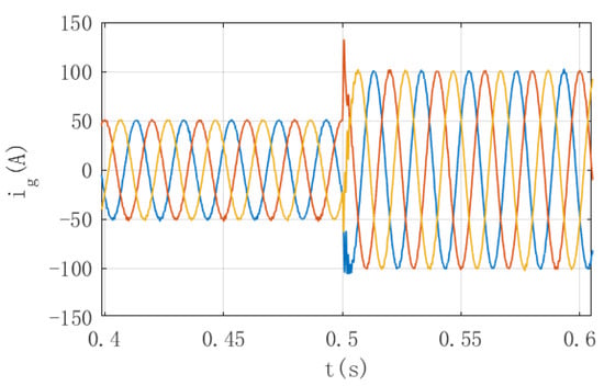
Figure 12.
Experimental waveform.
6. Conclusions
In this paper, aiming at the potential system resonance and system uncertainty of LCL filter, the system is reduced from the third order to the first order by splitting the capacitor, and a LADRC control method of grid-connected inverter based on LCCL is proposed. This method classifies the internal disturbances (system coupling and parameter perturbation) and external disturbances (changes of grid voltage and unknown disturbances) of the system as generalized disturbances, and adjusts the system through LESO and control law. In addition, considering the uncertainty of the system, passive damping is added at the second capacitor to improve the stability of the system. Finally, a simulation and experimental platform is building, which is used to verify the stability of the LADRC control strategy when the power suddenly changes or the grid voltage drops. After adding passive damping, the quality of the grid current becomes higher and the harmonics become smaller. Thus, the effectiveness and stability of the system are demonstrated.
Author Contributions
Conceptualization, G.H. and G.C.; data curation, G.H. and G.C.; formal analysis, G.H. and G.C.; funding acquisition, G.H.; Investigation, Y.D.; Methodology, G.H. and G.C.; resources, G.H.; software, G.H. and G.C.; supervision, G.H.; validation, G.C. and W.Z.; visualization, G.L.; writing—original draft, G.H. and G.C.; writing—review and editing, G.H. and G.C. All authors have read and agreed to the published version of the manuscript.
Funding
This research was funded by Natural Science Fund Project of Henan Province, China, grant number 222300420400. Project name is DC component suppression research for renewable grid-connected inverter system. Project host is He Guofeng.
Informed Consent Statement
Informed consent was obtained from all subjects involved in the study.
Data Availability Statement
The data presented in this research study are available in this article.
Conflicts of Interest
The authors declare no conflict of interest.
References
- Blaabjerg, F.; Teodorescu, R.; Liserre, M.; Timbus, A.V. Overview of control and grid synchronization for distributed power generation systems. IEEE Trans. Ind. Electron. 2006, 53, 1398–1409. [Google Scholar] [CrossRef] [Green Version]
- Ruan, X. Control Technology of LCL Grid-Connected Inverter; Science Press: Beijing, China, 2015; pp. 4–10. [Google Scholar]
- Guan, Y.; Wang, Y.; Xie, Y.; Liang, Y.; Lin, A.; Wang, X. The dual-current control strategy of grid-connected inverter with LCL filter. IEEE Trans. Power Electron. 2019, 34, 5940–5952. [Google Scholar] [CrossRef]
- Gao, J.; Tu, C.; Xiao, F.; Guo, Q.; Zou, K.; Jiang, F. Stability difference analysis of LCL filter grid-connected inverter in different domains based on SISO impedance model under weak grid. J. Electr. Eng. China 2021, 34, 5940–5952. [Google Scholar]
- Liserre, M.; Blaabejerg, F.; Hansen, S. Design and control of an LCL-filter-based three-phase active rectifier. IEEE Trans. Ind. Appl. 2005, 41, 1281–1291. [Google Scholar] [CrossRef]
- Zhu, J.; Liu, C.; Chen, P. Research on control technology of microgrid LCL grid-connected inverter. Sci. Technol. Innov. 2021, 1, 156–158. [Google Scholar]
- Yin, W.; Ma, Y. Research on Three-Phase PV Grid-Connected Inverter Based on LCL Filter. In Proceedings of the IEEE Industrial Electronics and Applications(ICIEA), Melbourne, Australia, 19–21 June 2013; pp. 1279–1283. [Google Scholar]
- Li, W.; Ruan, X.; Pan, D.; Wang, X. Full-feedforward schemes of grid volt ages for a three-phase LCL-type grid-connected inverter. IEEE Trans. Ind. Electron. 2013, 60, 2237–2250. [Google Scholar] [CrossRef]
- Vieira, R.P.; Martins, L.T.; Massing, J.R.; Stefanello, M. Sliding mode controller in a multi-loop framework for a grid-connected VSI with LCL filter. IEEE Trans. Ind. Electron. 2018, 65, 4714–4723. [Google Scholar] [CrossRef]
- Shen, G.; Xu, D. LCL filter grid-connected inverter split capacitor current control. Chin. J. Electr. Eng. 2008, 28, 36–41. [Google Scholar]
- Wang, H.; Wang, H.; Zhang, J.; Cai, X. Split capacitor passive damping control for LCL grid-connected inverter. Power Syst. Technol. 2014, 38, 895–902. [Google Scholar]
- Han, J. Active Disturbance Rejection Control Technology: Control Technology for Estimating Compensation Uncertainty; National Defense Industry Press: Beijing, China, 2008; pp. 221–237. [Google Scholar]
- Li, J.; Qi, X.; Wan, H.; Xia, Y. Active disturbance rejection control: Summary and prospect of research results. Control. Theory Appl. 2017, 34, 281–295. [Google Scholar]
- Gao, Z. Scaling and Bandwidth-Parameterization Based Controller Tuning. In Proceedings of the American Control Conference, Denver, CO, USA, 4–6 June 2003; pp. 4989–4996. [Google Scholar]
- Wang, G.; Liu, R.; Zhao, N.; Ding, D.; Xu, D. Enhanced linear ADRC strategy for HF pulse voltage signal injection-based sensorless IPMSM drives. IEEE Trans. Power Electron. 2019, 34, 514–525. [Google Scholar] [CrossRef]
- Xue, W.; Madonski, R.; Lakomy, K.; Gao, Z.; Huang, Y. Add-on module of active disturbance rejection for set-point tracking of motion control systems. IEEE Trans.Ind.Appl. 2017, 53, 4028–4040. [Google Scholar] [CrossRef]
- Chen, Z.; Liao, J.; Liu, G. Active disturbance rejection control algorithm and experimental study of new electro-hydraulic steering gear. China Ship Res. 2022, 17, 166–175. [Google Scholar]
- Rui, H.; Cao, W.; Wang, T. Research on path tracking control of PV cleaning robot based on improved ADRC. Mech. Des. 2021, 38 (Suppl. S2), 79–83. [Google Scholar]
- Ma, Y.; Zhao, J.; Zhou, X.; Tian, C. Linear active disturbance rejection control and stability analysis of parallel hybrid active power filter. Power Grid Technol. 2012, 36, 211–216. [Google Scholar]
- Benrabah, A.; Xu, D.; Wang, X.; Blaabjerg, F. Robust Active Damping Control of LCL fifiltered Grid Connected Converter Based Active Disturbance Rejection Control. In Proceedings of the IEEE Conference on Power Electronics and Motion Control, Varna, Bulgaria, 22–26 May 2016; pp. 2661–2666. [Google Scholar]
- Ma, M.; Liao, P.; Cai, Y.; Lei, E.; He, Y. ADR Control Strategy of LCL Grid-connected Inverter. High Volt. Technol. 2021, 47, 2223–2231. [Google Scholar]
- Yang, L.; Zeng, J.; Huang, Z. Application of linear active disturbance rejection technology in LCL inverter grid-connected current control and active damping. Power Grid Technol. 2019, 43, 1378–1386. [Google Scholar]
- Wang, B.; Xu, Y.; Shen, Z.; Zou, J.; Li, C.; Liu, H. Current control of grid-connected inverter with LCL fifilter based on extended-state observer estimations using single sensor and achieving improved robust observation dynamics. IEEE Trans. Ind. Electron. 2017, 64, 5428–5439. [Google Scholar] [CrossRef]
Publisher’s Note: MDPI stays neutral with regard to jurisdictional claims in published maps and institutional affiliations. |
© 2022 by the authors. Licensee MDPI, Basel, Switzerland. This article is an open access article distributed under the terms and conditions of the Creative Commons Attribution (CC BY) license (https://creativecommons.org/licenses/by/4.0/).