1. Introduction
With the goal to reduce carbon emissions for limiting the effects of global warming and the growing interest in being largely independent of energy imports for political reasons, the importance of renewable energy, electrification of transportation and solutions for efficient and reliable grid integration is increasing [
1]. The use of dc distribution in addition to ac can be advantageous considering that photovoltaic and battery storage systems as new backbones of electric power supply and loads such as electric vehicle chargers are dc-based technologies. Less conversion stages are required in dc distribution for grid integration of such systems, thus avoiding conversion losses and increasing efficiency [
2]. A voltage level of up to 1500 V can be adopted in order to increase the transmittable power without leaving the low voltage level [
3]. Besides, a bipolar system can be used so as to increase the number of utilizable voltage levels.
LVDC distribution requires power converters to supply and control the dc grid voltage and, if not operated as isolated systems, the grid-forming converters can serve as connection point to the existing ac grid infrastructure. These power converters can be voltage source converters (VSC) connected to the ac grid via a transformer in order to provide a galvanic isolation. An upcoming solution is the SST [
4] that is a modular converter concept, inherently galvanically isolated due to the use of medium-frequency transformers, offering lower volume and weight as well as reduced losses in comparison to the VSC solution.
While the advantages of employing LVDC distribution in the case that interfaced systems are mainly dc-based are clear, for example, to connect multiple (fast) charging stations to the grid, challenges still exist in the availability and selection of protection devices, their coordination and the realization of selectivity [
5]. Significant research has been carried out in this field already. In [
6], a protection scheme utilizing current interrupting devices, protective relays, measurement equipment, and grounding has been proposed. However, this method suffers from problems to detect high impedance faults. Thus, in [
7] a method to detect these high impedance faults using periodically forced harmonic oscillator and bifurcation theory is presented. In order to increase the selectivity an improved strategy is shown in [
8]. Another advanced protection scheme is presented in [
3] but besides the need of communication, such solutions that adopt ac protection schemes require fast dc breakers meeting the requirements of the IEC 60898-3 standard [
9], which are not readily available and costly. In addition, the standard only applies to circuit breakers for up to 440 V. In contrast, dc fuses are a cheap protection device and it is shown in [
10] that they can be used for the protection of radial dc grids. However, power converters are fast-acting in over-current situations to protect themselves in respect to their limited over-current capability, and, as controlled devices, should directly participate in the protection scheme.
This work proposes to use the control capability of power converters for protection against short-circuit faults in the branches of an LVDC feeder by implementing a two-layer protection technique. Assuming that droop control is implemented for voltage control, a virtual resistance method is used as the first layer of the protection technique to limit the LVDC bus current in case of a short-circuit fault in one of the feeder branches and to avoid tripping of the grid-forming VSC. For the second layer, a soft fuse tripping method is proposed that is implemented in the converter control of the dc–dc converters emulating the physical behavior of dc fuses but allowing for parameter adjustments. The considered LVDC feeder is supplied by a VSC and several charging stations are connected by dc–dc converters at its branches. In this scenario, the short-circuit fault at a feeder branch and its protection procedure are investigated. The purpose is to achieve fast reaction on the fault, meanwhile, tripping of the grid-forming VSC is avoided. To facilitate the analysis, an ideal grid on the LVAC side is assumed. The proposed method can be an addition to the existing circuit breakers. It increases the reliability of the system by adding more layers of protection and also reduces the number of times the circuit breakers have to trip, which further increases the reliability. On top of that, this method is control-based and does not require any additional components or communication, and thus comes with zero costs.
An initial version of the manuscript including the proposed method was presented in [
11], this version further extends with a generalized short-circuit fault analysis followed by a more comprehensive stability analysis and HIL-based experimental verification. The paper is organized as follows. In
Section 2, the normal operation conditions of the voltage droop controlled grid-forming VSC are investigated.
Section 3 analyzes the steady-state of the circuit in no-fault and short-circuit fault situations, and the range of virtual resistance to suppress the bus current of the fault situation is derived. Moreover, the proposed two-layer protection technique is discussed. The specifications of the LVDC feeder are listed in
Section 4. Based on these, the dc-side output impedance model of the voltage droop controlled grid-forming VSC is proposed and verified, and the system stability and transient performance are investigated in
Section 5.
Section 6 presents the experimental results and conclusions are drawn in
Section 7.
2. Normal Operation Conditions of Droop Controlled Grid-Forming VSC
Before investigating the short-circuit fault at an LVDC feeder branch, the normal operation conditions of droop controlled grid-forming VSC needs to be computed firstly. If the power demand of the loads exceeds the maximum output power, the LVDC feeder voltage will collapse and lose the controllability.
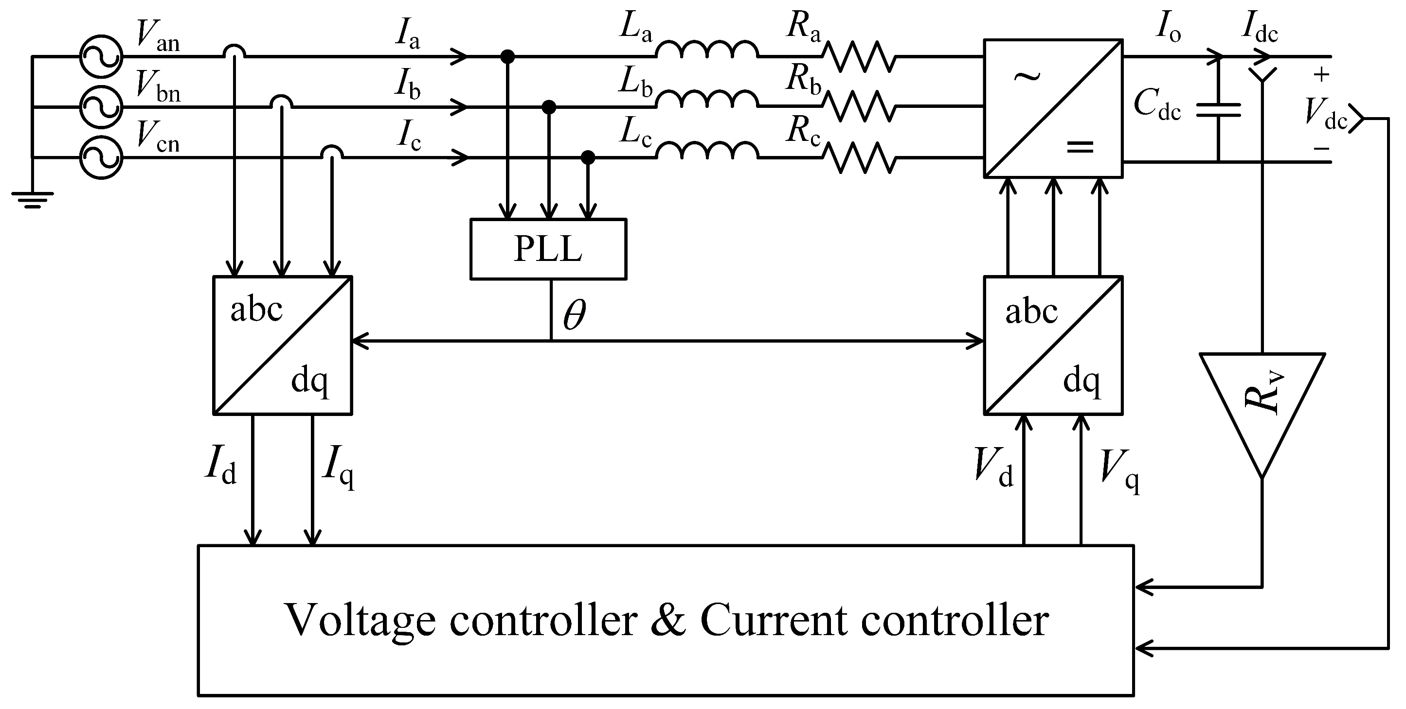
Figure 1 shows the control structure of a voltage droop controlled grid-forming VSC.
,
and
are the phase voltages,
,
and
are the phase currents flowing from ac side to dc side,
,
and
are the filter inductance,
,
and
are the filter resistance.
is the output current of VSC,
is the dc side capacitance of rectifier,
and
are the voltage and current of dc bus,
and
are the phase current in
domain,
and
are the output of current controller,
is the virtual resistance for droop control and
is the angle generated by PLL. In this case,
is set to zero to maximize the active power.
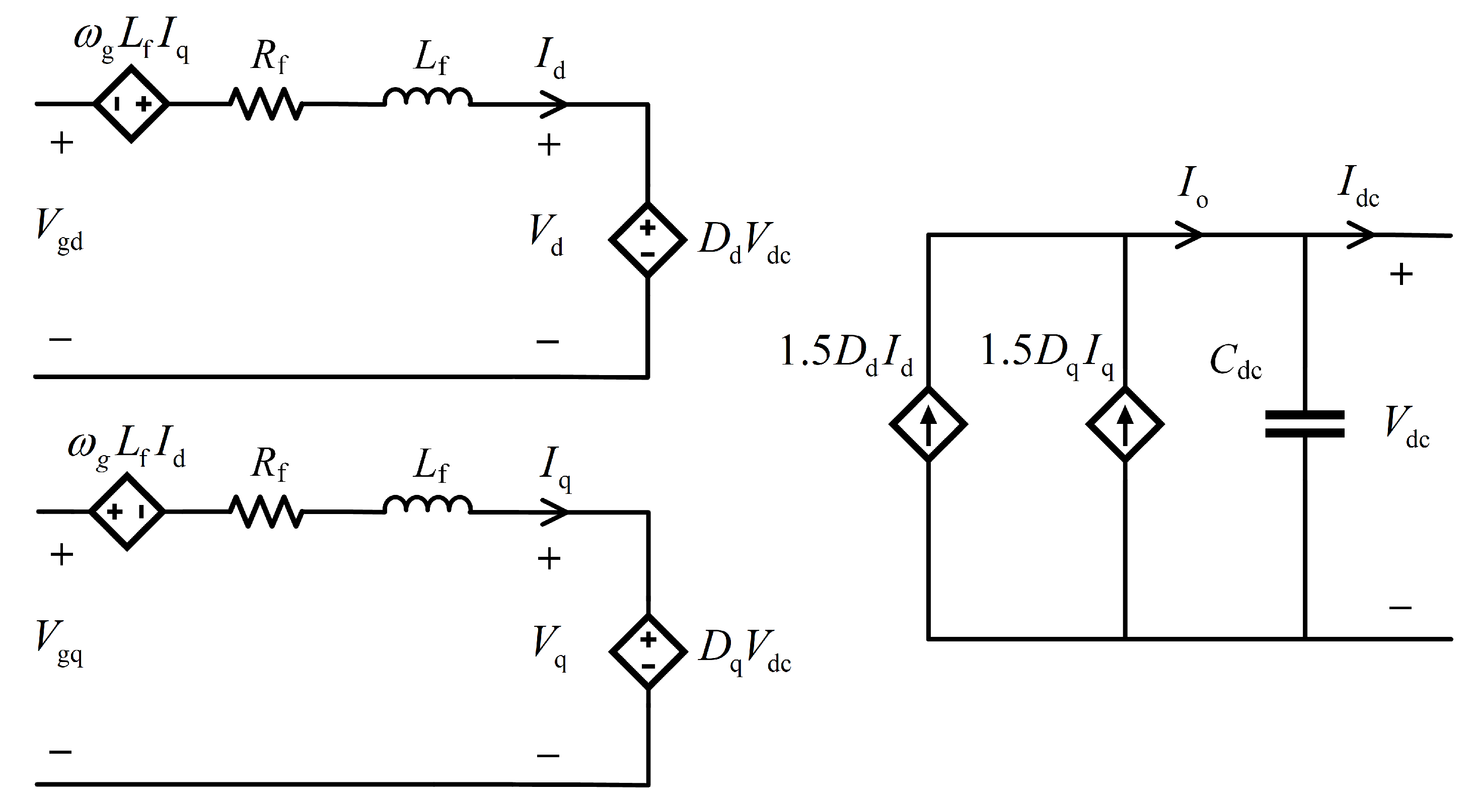
With the assumption that the grid is ideal, the phase components can be converted into the ones in d-q domain through the Clarke-Park transformation. The open-loop model of the VSC is presented in
Figure 2, where
is the fundamental frequency of the grid,
and
are the diagonal equivalent resistance and inductance of the filter of VSC in
domain,
and
are the corresponding duty cycle of
and
.
and
are the grid phase voltage in
domain, given as
By applying the KVL, the voltage equations in
Figure 2 can be obtained as
At the steady state,
is equal to zero and
, the equation of active power is given as
Firstly, the active power limited by dc side is considered. To guarantee that
has real solutions, the following inequality must be satisfied:
Hence, the range of active power is given as
Secondly, the limitation of active power by AC side needs to be computed. By replacing
in (
3) with (
2), the equation of active power becomes
By observing the equation above, the range of active power depending on
can be calculated as
Therefore, on the premise that the VSC is individually stable, the maximum output power of VSC can be concluded by referring the calculated ranges above, shown as
Besides, it is worth mentioning that the output voltage of VSC has minimum value regarding the modulation method, and being lower than minimum value will also make the VSC lose the controllability. Hence, the virtual resistance is limited by the minimum value of the output voltage which will be presented in the following analysis.
3. Short-Circuit Fault Analysis and Protection
In this section, the DAB converter represents a controlled dc–dc converter, and it is considered as a use case for the charging stations connecting to the feeder of the LVDC distribution, that often require a galvanic separation between the car and the line. The choice of the dc–dc converter topology minimally affects the following analysis. The steady state analysis is done when short-circuit fault happens to one of the charging stations. With the analysis, the protection techniques are proposed.
3.1. Short-Circuit Fault Analysis
Short-circuit currents and characteristics can be obtained by applying the IEC 61660 standard [
12]. However, Ref. [
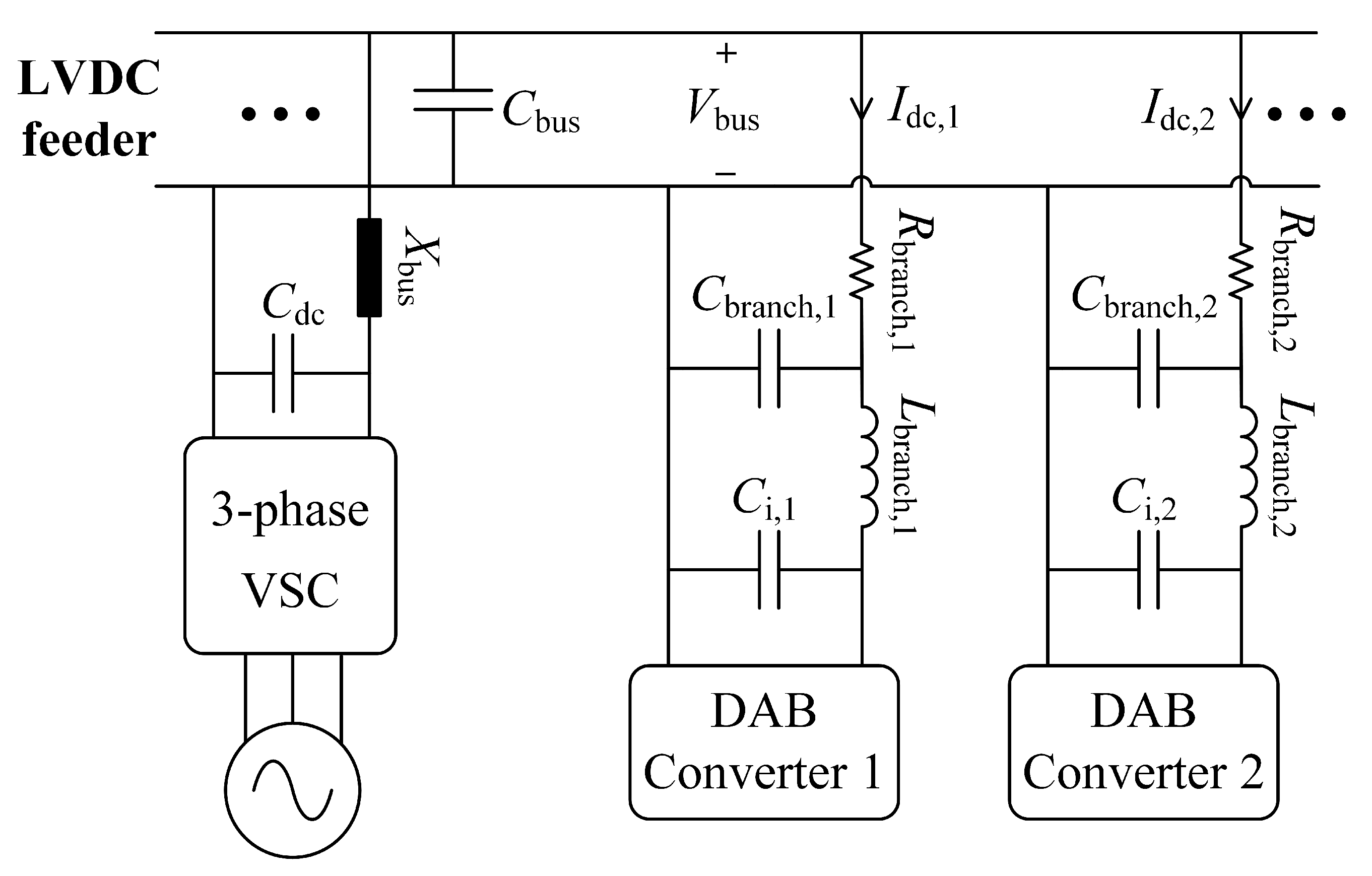
13] shows that the real short-circuit current can be considerably different from that. Hence, for this study, an example network (
Figure 3) will be used utilizing a charging stations at the LVDC feeder. In this figure
is the cable inductance and resistance of the dc bus,
is the filter capacitance of the dc bus,
,
and
form the cable impedance of each charging station branch, and
is the input capacitance of DAB converters.
Assume that there are
n charging stations connected to the LVDC feeder, the dc bus current
can be given as
where
is the input dc current of branch
k. It can be seen from
Figure 3 that the voltage of the LVDC feeder is exactly the input voltage of each branch, calculated as
Considering that the
branch has short-circuit fault at one moment and has low short resistance
, meanwhile, the system power does not exceed the maximum power and the system is stable, at steady state it exists
where
is the short-circuit current. By re-arranging the above equation, the dc bus current during short-circuit fault can be represented as
Since the power losses on the branch cable is very small, it exists
, and the above equation can be further simplified as
Hereto, the relationship between the dc bus current
and the short-circuit current
of the
branch becomes explicit. To check the detailed influence of the short-circuit current
to the dc bus current
, the derivative of
to
is taken and given as
where
is the power of short-circuit branch. As
is non-negative, it is easy to find the above derivative is monotonically increasing. The minimum value of
is influenced by the value of
, where the situation needs to be discussed by comparing the power of short-circuit branch and the power of other no-fault branches:
where
is the minimum value of
. It can be concluded from above equations that the minimum value of
depends on the threshold that if the minimum power of short-circuit fault branch is larger than the sum of power of other no-fault branches, i.e., if the proportion of
to system total power exceeds 50 percent or not.
The value of
is determined by the short-circuit resistance
and the minimum dc bus voltage during the fault. Regarding the short-circuit resistance is fixed, the minimum dc bus voltage
becomes the only factor to influence the value, which depends on the modulation method of grid-forming VSC. Considering that the cross-section of bus cable is designed large for high current, the bus resistance
can be very small and the voltage drop on it can be ignored. Therefore, the minimum dc bus voltage generated by the SPWM and SVPWM are given as follows:
In this paper, the SPWM is adopted for the VSC. With the known value of
, the value of
and the minimum value of
can be calculated, shown as
3.2. Protection Techniques
Combined with the analysis above, the protection techniques are proposed to reduce the bus current in a fault condition. The protection procedure is divided into two layers:
When a short-circuit fault occurs in one branch, the first layer is activated and the bus current is limited by the virtual resistance for a moment. After that, the second layer is activated so that the fault branch is tripped by the control of soft fuse, protecting the other power electronics in the system. Furthermore, depending on the fault conditions, the control reaction of the grid-forming VSC can be insufficient to stabilize the system. An ac breaker is required for this case on the ac side of the VSC to completely de-energize the dc bus. Since it implies a disruption of the ac service, this operation will not be covered in the paper.
3.2.1. Voltage Droop Control-Based Bus Current Limiting
It is well known that the droop control is a good approach to achieve power sharing among multiple sources. In this paper, another advantage of the voltage droop control by source side is depicted, i.e., bus current reduction by the proper virtual resistance during the short-circuit fault. With this benefit, it can avoid tripping of grid-forming VSC itself. In no-fault situation, the system power is nearly constant regardless of
. Referring to (
5), the value of
is constrained for real solutions of
, shown as the following inequality:
When the short-circuit fault happens to one branch, the system power is not constant anymore that can be influenced by
. The effective range of
to limit the bus current during the fault is given as
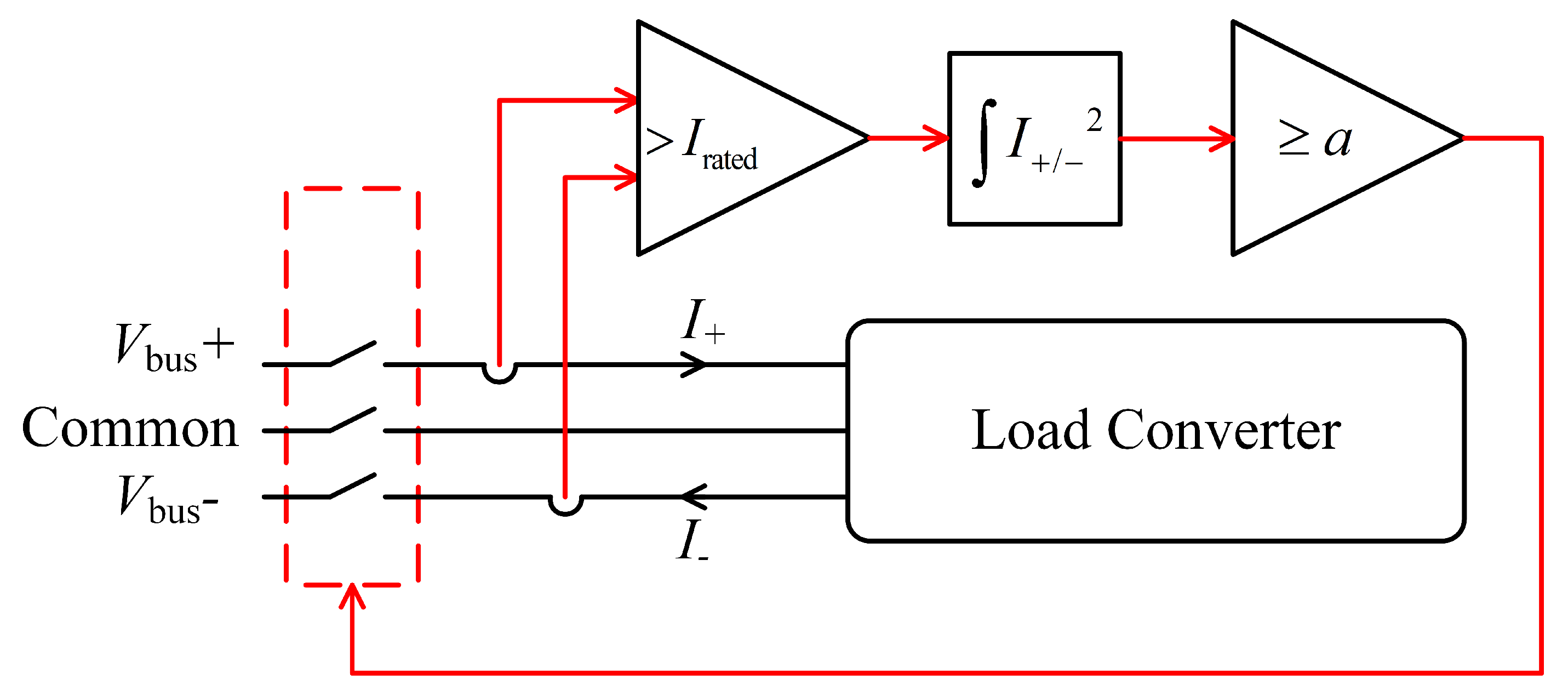
3.2.2. Soft Fuse Tripping
The fuses are regarded as one main protection device in grid application. The fuse is formed by a fuse link and heat-absorbing material that suppresses the arc [
6]. However, it is also known that the physical fuses have large time constants. In this paper, a control-based soft fuse tripping approach is proposed as the second layer protection for the system. The control mimics the physical characteristic of the fuse but is also more flexible since the parameters can be adjusted.
Figure 4 shows the control schematic of the soft fuse tripping, where
and
are the bus currents and
is the rated RMS current and
a is the pre-arc value referring to the datasheet of fuse [
14].
5. The Influence of Virtual Resistance on System Stability
Beside the limitation by the circuit parameters, the influence of virtual resistance on system stability becomes another concern. Usually, the transients of a system can be improved by increasing the controller bandwidth, indicating better performance on dynamics. However, this also brings the system to instability [
16]. Not only that, the addition of virtual resistance also deteriorates the system stability [
11,
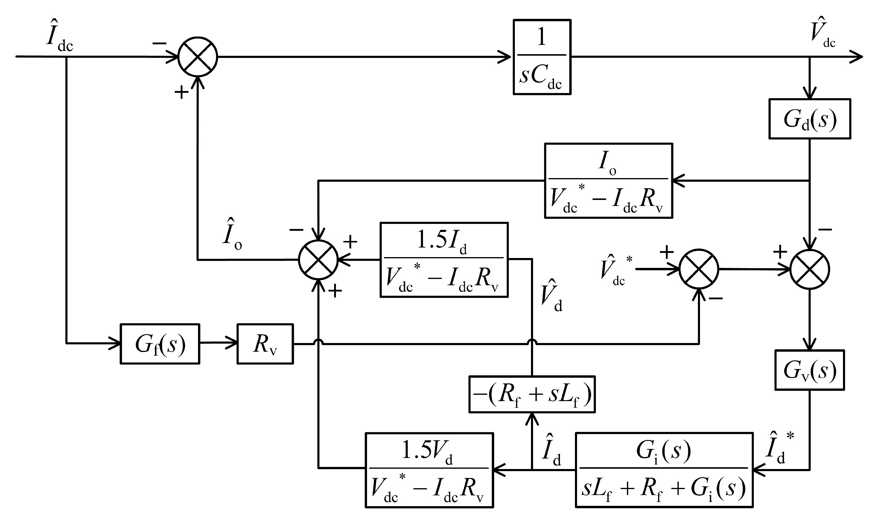
17]. Hence, there is trade-off between system stability and performance. In this paper, the system stability is analyzed during the no-fault situation only because the fault situation is short and will be terminated by the soft fuse tripping. The impedance-based stability analysis is adopted. The dc side output impedance of PMSG has been derived in [
18] and verified in [
16]. By neglecting the dynamics of PLL, the dc side output impedance of grid-forming VSC is similar to the one of PMSG where the control is voltage-oriented rather than field-oriented. Referring to the impedance model in [
18], the transfer function block scheme of the voltage droop controlled VSC is proposed in
Figure 5. Hence, the output impedance of grid-forming VSC can be calculated as
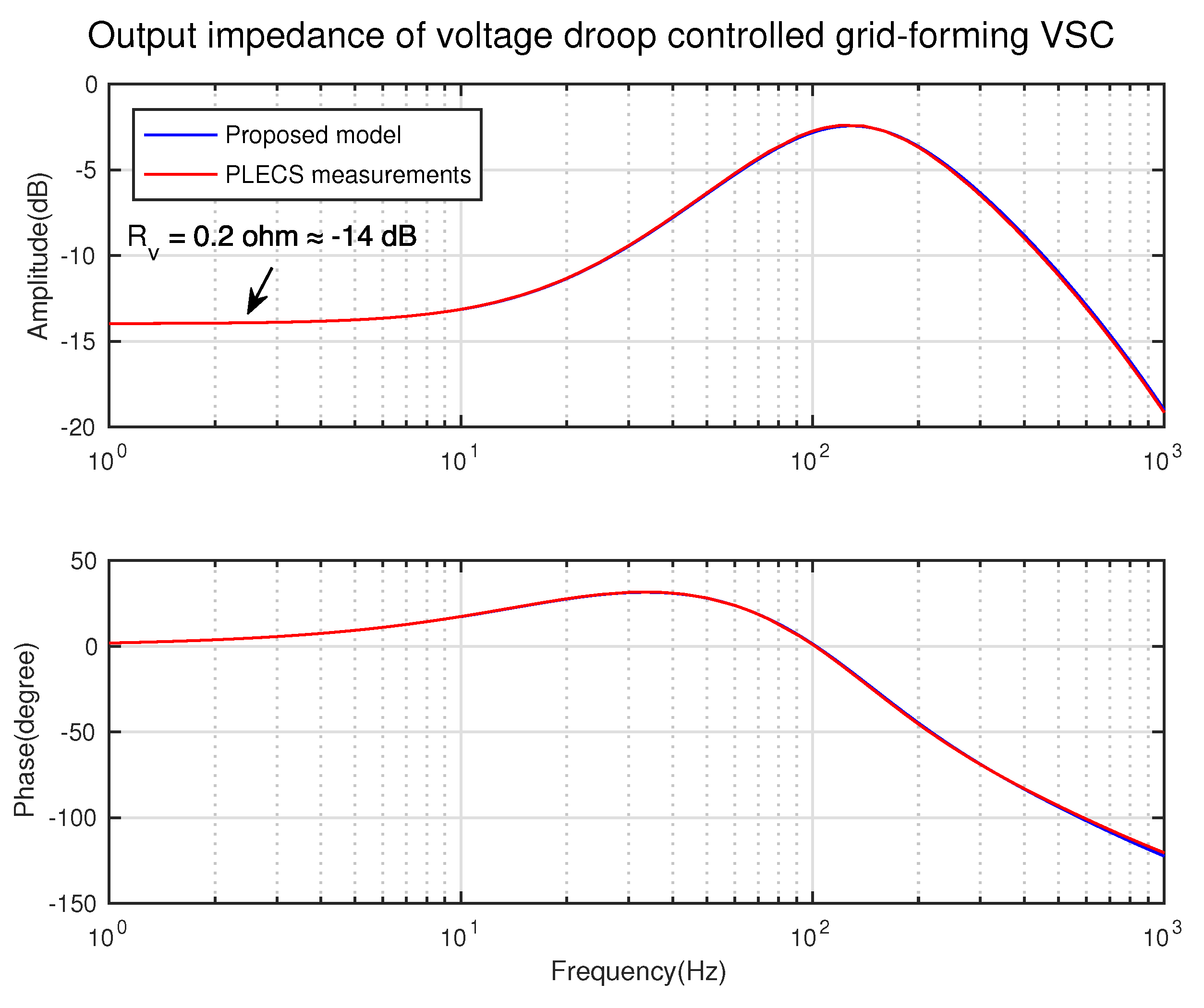
To validate the output impedance of voltage droop controlled grid-forming VSC, a switching model is built in PLECS. By adding a current source containing both dc and an ac sinusoidal component to the output of the VSC, the output impedance at specific frequency can be calculated.
Figure 6 shows the validation results, a good match can be seen between proposed model and PLECS measurements. It also can be seen that the low frequencies of output impedance are dominated by the virtual resistance
. The input impedance of DAB converter has been derived in [
19] and verified in [
16]. The derivation process is omitted here.
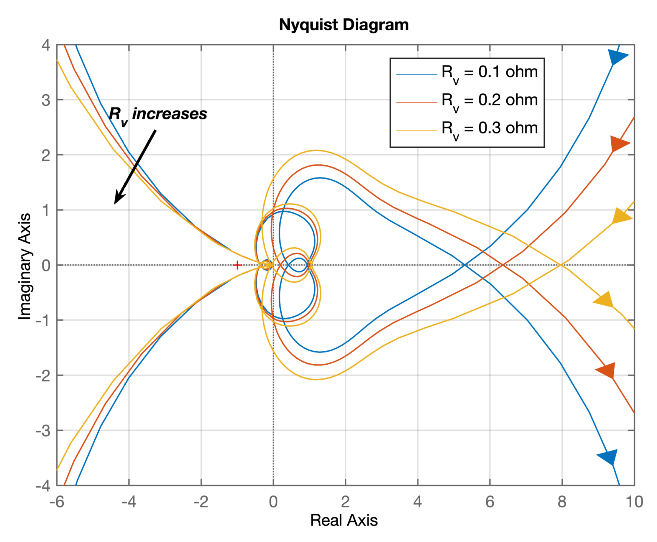
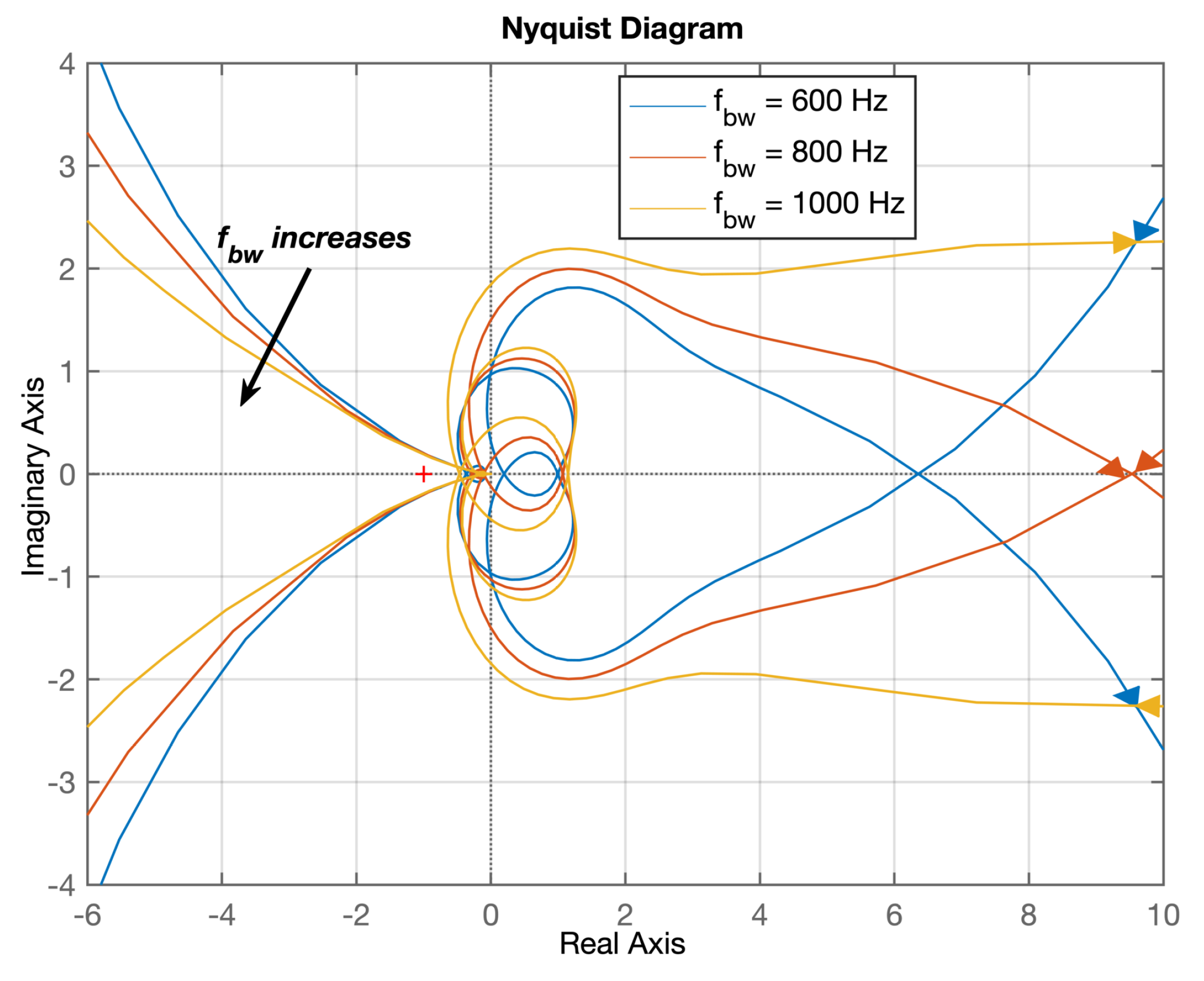
With the obtained impedance model of grid-forming VSC and DAB converter, the stability analysis can be carried out with Nyquist criterion, which is a sufficient and necessary condition for a stable system. To better observe the influence of virtual resistance and current controller bandwidth on system stability, the low-pass filter
of virtual resistance is temporarily removed during plotting Nyquist curves.
Figure 7 shows the Nyquist contour of system minor loop gain with different value of
at rated power. It can be seen that the system tends to instability by increase of
.
Figure 8 shows the Nyquist contour with different bandwidth of current controller at rated power with
equal to
. It is noted that the increase of bandwidth makes the system go to instability.
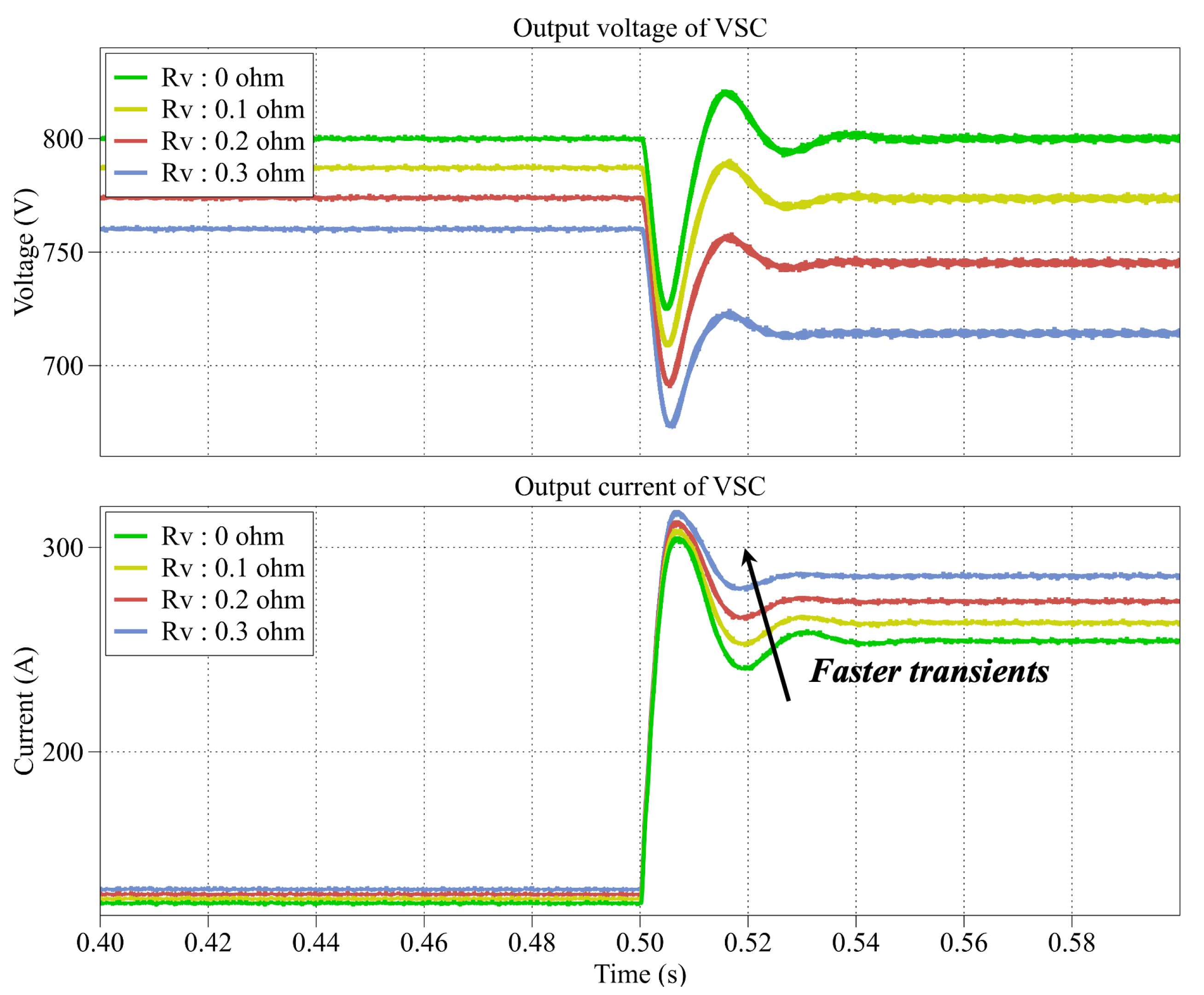
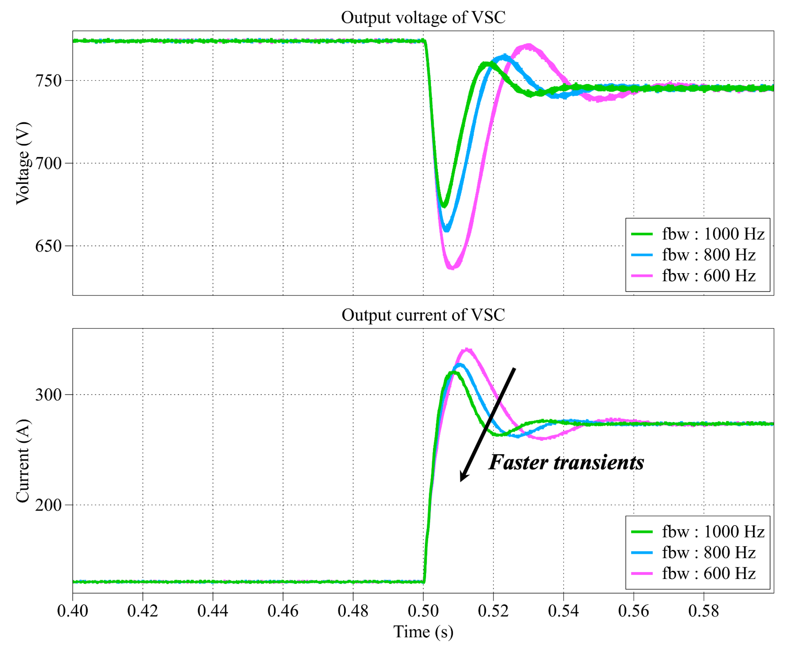
On the other hand, since the Nyquist contour can hardly reflect the transient performance of system by varying virtual resistance or bandwidth of current controller, the system is simulated in time domain by PLECS. A load step is given from 50 kW to 100 kW to observe the transients of output voltage and current of VSC, shown as
Figure 9 and
Figure 10. It can be seen that the transients can be improved with larger virtual resistance and higher bandwidth of current controller. Hence, in system design, the virtual resistance and the control parameters must be adjusted to meet the requirements of stability and transient performance.
6. Experimental Verification
Considering the difficulty of verifying the results in previous section with practical circuit, in this section, the experiment is carried out with RTBox-based HIL. The real-time simulation step is set as 10
s. The turn-on delay of switch is set as 0.25
s. The effect of protection techniques is investigated with no virtual resistance, virtual resistance equal to
and equal to
.
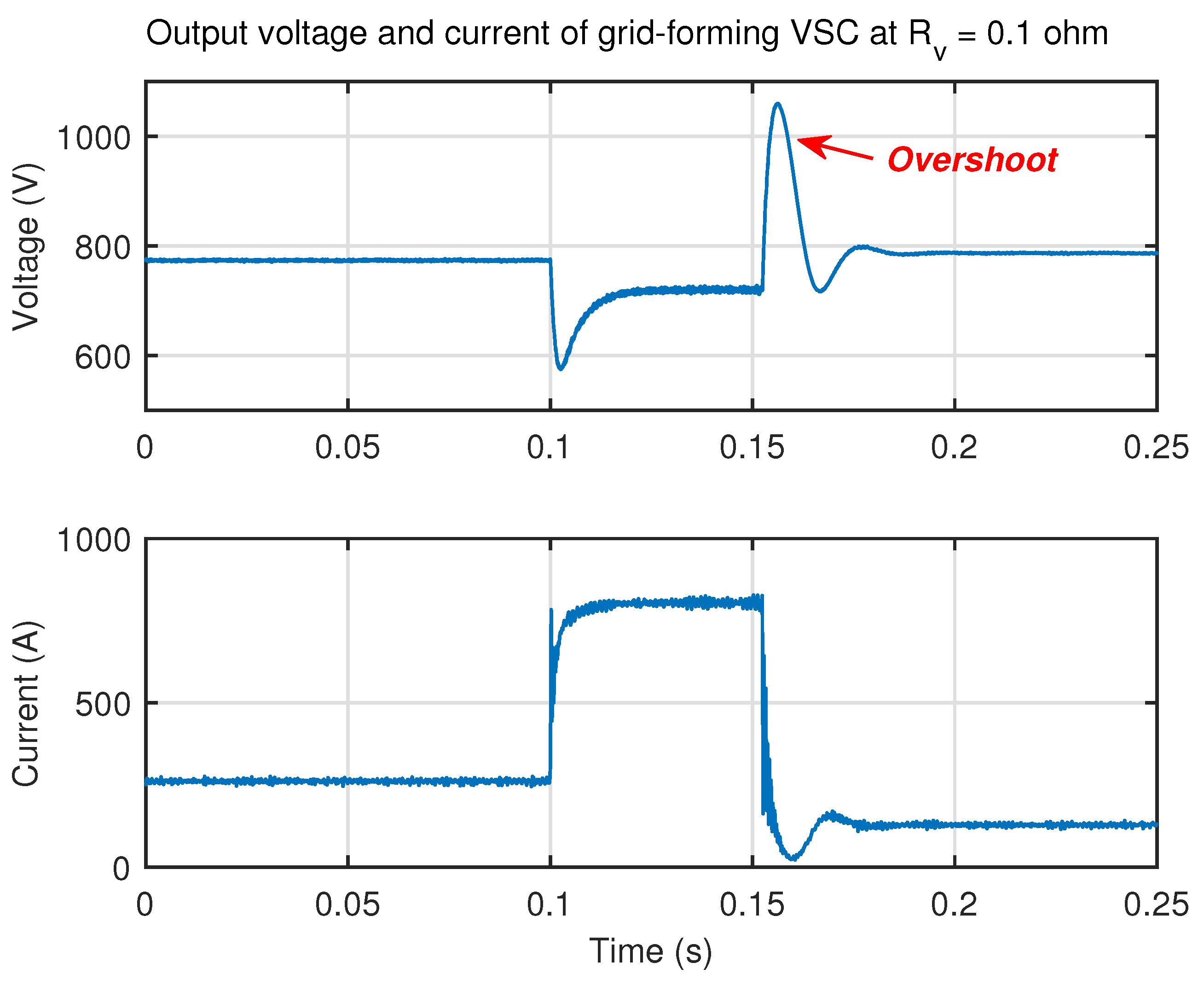
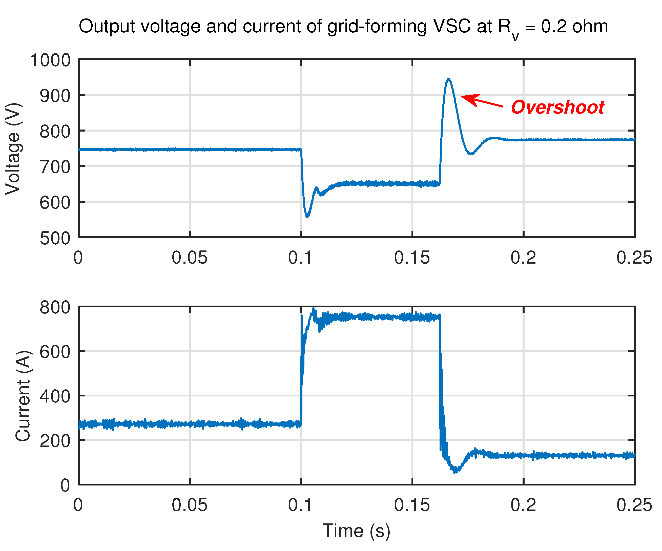
Figure 11,
Figure 12 and
Figure 13 show the output waveforms of grid-forming VSC in these three cases. By comparing these three figures, it can be seen that the virtual resistance can effectively reduce the bus current during short-circuit fault which starts at
t = 0.1 s.
In addition, it can be seen in
Figure 13 that the output voltage of VSC reaches around 650 V when
is equal to
during the fault, validating the calculated results of analysis section. Moreover, it can be seen that with the increase of virtual resistance, the voltage overshoot after the soft fuse tripping is reduced, indicating that the larger virtual resistance improves the transient performance, which is consistent to the conclusion obtained from
Figure 9.
7. Conclusions
This paper proposes a two-layer protection technique for the short-circuit fault at LVDC feeders, which can be regarded as a possible ancillary service to avoid the tripping at LVAC side of the grid-forming VSC. Firstly, the conditions for normal operation of droop controlled grid-forming VSC are given. Then, the system during short-circuit fault is analyzed, and the virtual resistance for minimizing bus current is computed while the controllability of VSC is not lost. Meanwhile, a two-layer protection technique is proposed to limit bus current during short-circuit fault and disconnect the short-circuit branch by a ’virtual fuse’. Furthermore, the system stability is well considered regarding the introduction of virtual resistance. The impedance-based stability analysis is carried out to highlight that the larger virtual resistance improves the transients and brings the system to instability. Hence, a trade-off among bus current limiting, transient performance and system stability exists, and it can be further investigated for system optimization. Last, the experimental verification is done by HIL based on PLECS RT Boxes. The experimental results are well matched with the analyzed results, proving that the analyses are properly conducted.


 ,
, 


