Abstract
In this paper a side-by-side comparison between synchronous reluctance machines (SynRMs) with concentrated and distributed windings is performed. The characteristics, parameters, and the installation space of a permanent magnet synchronous machine (PMSM) with concentrated windings used in a 13 V automotive cooling fan system (CFMs) are used as requirements and specifications. For that, eight SynRMs with different stator and rotor topologies are investigated and optimized by means of FE-based electromagnetic optimization. Knowing the challenges associated with the development of mechanically stable SynRM rotor structures, for two selected cross-sections in view of being prototyped, designs checks are performed to ensure robust operation at up to two times the required operating speed. The simulated results were verified by means of measurements performed using two different types of loading systems, i.e., with the real ventilator and using a DC machine as a load. Based on this, the relative differences between all three motor technologies in terms of important quantities (e.g., torque-speed characteristic, torque ripple, efficiency, power factor and ultimately the size) are highlighted.
1. Introduction
Synchronous reluctance machines (SynRMs) with distributed windings (DW) have already proven to be a serious competitor for other magnet-free topologies (e.g., induction machines—IMs) [1,2]. Not the same can be said about their concentrated windings (CW) variant, where research activities are rather scarce [3,4]. The possibility to design such machines for low voltage (<60 V) applications—typical for the automotive industry (non-traction)—is explored even less.
On the one hand, this lack of activity is justified (to some extent) by the fact that CW-machines show rather modest saliency ratios and thus undeniable differences in terms of size and required input power are expected when comparing to other types of synchronous motors with winding-free rotors, e.g., the DW-SynRM and permanent magnet synchronous machines (PMSMs). On the other hand, this kind of work can be useful for mapping the CW-SynRMs into the synchronous machines class, i.e., to show with solid and well-documented results (both at the numerical and experimental level) what are the differences when referring them to the other two. Therefore, to highlight the attributes but also the limitations of this technology, various analyses are being carried out for answering the question: What should one undertake to design a FSCW-SynRM with the same output as an DW-SynRM and ultimately with a PMSM?
To answer that, a comparative study between eight SynRM topologies both with CW (6/4, 9/4, 12/4, 9/6) and DW (24/4, 27/4, 33/4, 27/6) is done by means of FE-electromagnetic analysis. The ferrite-based spoke-type fractional slot concentrated windings (FSCW) PMSM is often referred to as the reference machines, as its parameters (including input power and installation space) and rated characteristics are used as design specifications and requirements. All the machines are used to drive a cooling fan for automotive applications, at room temperature.
The influence of various cross-section (CS) geometrical parameters on important output quantities (i.e., average torque and torque ripple, d- and q-inductances, efficiency, and power factor) is analyzed. Knowing that the process of designing such machines has a rather conflicting character, where superior behavior in terms of electromagnetics usually means a degradation of the rotor’s mechanical robustness, special attention is dedicated to the later aspect.
Following a brief state-of-the-art regarding research activities in this field, some concepts, and the historical evolution of the machine under study are presented in Section 2, along with few rather basic design guidelines. The next section is dedicated to optimization related topics based on fully parametrized cross-sections. Following the optimization procedure, in Section 4, for each of the eight studied motor topologies the best designs are selected and compared both in terms of static and peak characteristics using the parameters obtained with FE-electromagnetic models. Out of this, two designs were selected (i.e., one with concentrated and one with distributed winding), and their validation regarding the rotor integrity at high speeds is performed in Section 5. These two designs are prototyped, and the simulated results are experimentally validated in Section 6, before concluding the paper in the last section.
2. Synchronous Reluctance Machine, Torque Production Mechanism and Constructive Variants
The SynRM has continuously improved since 1923 when Kostko [5] presented the first experimental model. Its stator is similar to that of conventional AC machines (e.g., electrically excited synchronous machine, IM), but the rotor evolved historically from adapted IM rotor laminations (Figure 1a,b), to the single (Figure 1c) [6] or multi-flux barriers topologies (Figure 1d). Two variants of the multi-flux barriers rotor, namely, axially, and transversally laminated can be seen in Figure 2. Besides the radial flux topologies, recently a concept for an axial flux SynRM was proposed [7]. Finally, the last evolution step for further enhancing the capabilities of these type of machines was to insert permanent magnets in their rotor structure [8].
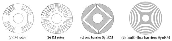
Figure 1.
Radial flux SynRM rotor examples evolution starting from the modified IM rotor (a,b) to state-of art rotor design for high performance SynRM (c,d) [6].
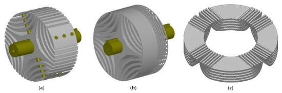
Figure 2.
(a) Axially laminated anisotropic (ALA) rotor, (b) Transversally laminated anisotropic (TLA) rotor, (c) Axial flux synchronous reluctance machine.
The motor produces the torque based on solely the reluctance principle, therefore in order to increase its torque/power density, the so-called saliency ratio, which is the ratio between the quadrature inductances (ξ = ) has to be maximized. This can be achieved by adequately designing the machine’s magnetic circuit. A key point in this is the proper concept and arrangement of the rotor flux barriers [9]. According to the work of Moghaddam [10] a very high number of barriers (e.g., higher than nine) does not have a major impact on the d-axis inductance, and thus on the average torque. However, the torque ripple is much more sensitive to this number. Furthermore, the type of winding is another important factor when designing for low torque ripple (more on that later). Finally, the more flux barriers one employs, the more difficult will be to design a robust rotor structure and a stable manufacturing process, without the need for highly precise (and tight) tolerance intervals. SynRMs are mainly seen as potential alternative for IM-drives, however in their conventional construction they still exhibit a power factor which is 5% to 10% lower than an IM [11]. The power factor is in direct relation with the saliency ratio as also reported in [10], where it is shown that for a machine to have a cos φ > 0.8, a ξ > 7 is needed. Unlike IM-drives, SynRMs have negligible rotor losses (at sufficiently low rotor field variations), and thus they can outperform the former in terms of efficiency. Knowing that the additional size of the inverter (when compared to that of the motor) is given by η∙cos φ, one could use the higher SynRMs efficiency capabilities to compensate for the larger reactive power needed to magnetize the iron core.
Another option to improve the power factor is to add a larger amount of weak magnets (e.g., ferrite with remanence around 0.4 T or even less) or a reduced quantity of high strength ones (e.g., NdFeBr with remanence values exceeding 1.3 T)—in both cases a permanent magnet assisted synchronous reluctance motor (PM-SynRM) is obtained [11,12]. Exemplifying for the ferrite case, thanks to the presence of the PMs, the newly added component of the torque (the synchronous one) can boost the torque up to 20%, but one has to pay attention also to the third one (cogging torque) with parasitic character which for quality purposes has to be minimized.
Excluding safety-critical and high-power/low-voltage applications as well as very large machines (e.g., generators), where higher number of phases are employed, most of the applications both in industrial case and automotive are 3-phased ones, with groups of phase coils symmetrically wound around the stator teeth.
Following the choice of the number of phases, the number of slots and poles along with the winding configuration are interdependent degrees of freedom (DoFs). Previous works [13,14,15,16] have shown that the 4-pole rotor topologies have the highest torque and efficiency. For machines with larger diameters, more poles can be used, and the number of slots has to be chosen accordingly to maximize the saliency. Trade-offs have to be made when increasing the number of poles [17], as the main advantages (e.g., reduction of active materials, higher torque density and efficiency) come with some drawbacks such as: higher flux leakage and commutation frequency as well as increased iron losses.
3. Design Optimization
For modern products, understanding how different physical phenomena interact is the way to ensure a safe and reliable function [18] while providing a competitive solution. On one hand, the electromagnetism is the field determining the exact shape of the rotor and stator laminations. On the other hand, an adequate heat and mechanical forces transfer, without losing structural integrity is required for preventing malfunction and defects in the machine.
FE-based multiphysics optimization can be performed by coupling the analysis of different physical phenomena. However, such an approach often results in prohibitive computation times. To overcome this, another option, and the one adopted in this work, is to isolate and analyze separately the various phenomena to obtain the best electromagnetic design, which also fulfills the operating requirements in terms of mechanical robustness and acoustics. All analyses, excepting the electromagnetic one, are to be seen as design checks.
FE-Based Electromagnetic Design Optimization
The CS of the SynRM is optimized based on a workflow build around the FE-electromagnetic model (further denoted as FE-model). A key-element in this is the rather complex rotor structure [19,20,21,22]. An evolutionary algorithm, namely, particle swarm optimization (PSO) is used to generate the parameter variations (so-called individuals) in the FE-model and to evaluate the objective functions. PSO is a technique that mimics the behavior of a flock of birds, where the information is spread among the individuals of the population [23]. A multi-objective optimization is performed, where the first target is to maximize the average torque (at given magnetomotive-force and fixed machine envelope, i.e., outer diameter and axial length) while minimizing the torque ripple. The geometrical parameters of the FE-model are the degrees of freedom (DoFs) in the optimization process. For limiting the search space, the values used for the dimensional parameters are bounded between upper and lower limits as shown in Table 1. All the parameters are explained in Figure 3.

Table 1.
Parameters in the optimization along with their variation interval.
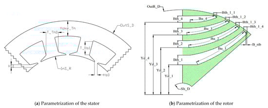
Figure 3.
Parametrization of the geometry of the model used in FEA-based optimization.
The optimization workflow (see Figure 4) starts with the process of reading the geometry data (Stage 1). The previously developed FE parametric model is then updated based on these parameters (Stage 2). Subsequently, some CS/geometry checks are performed both in terms of geometrical feasibility and windability (i.e., if the desired number of turns at given diameter have enough room in the slot). To save processing time, for non-valid structures the simulation is aborted immediately (Stage 3). A Python script is used to handle the CS checks and to implement parallel processing for faster computation. Further, during Stage 4, the simulations are performed and the outputs (e.g., the electromagnetic torque waveform) is exported and supplied as data-table to the optimization software. In Stage 5 the optimizer reads this data, evaluates the objective functions (in this example the average torque and its ripple), and if the termination criteria are not fulfilled it generates new parameters and the process is restarted from Stage 2.
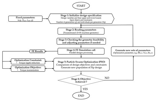
Figure 4.
FE-based electromagnetic optimization workflow for the SynRM under study.
Finally, a 12-slots 4-pole SynRM is used as case study for explaining the optimization process and the objectives sensitivity to various design variables.
Prior to the optimization, a sensitivity analysis is conducted in order to get a deeper understanding about the key-parameters of the SynRM’s structure and their influence on the considered objectives. Scatter plots of about 2000 evaluated designs are given in Figure 5 showing the torque capability of the motor as function of various rotor and stator geometric parameters.
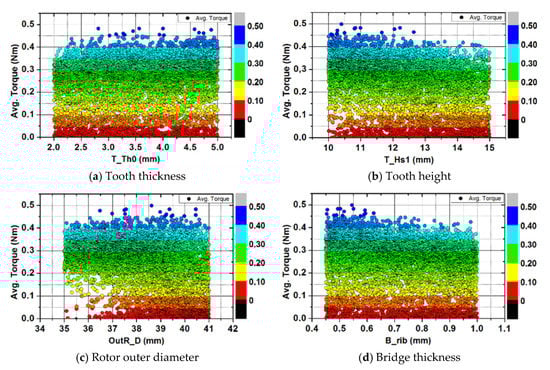
Figure 5.
Sensitivity analysis for different geometric parameters and their impact on average torque.
As expected, increasing the rotor outer diameter, the tooth thickness and decreasing the bridge thickness, an enhancement in machine’s torque capability is obtained. Moreover, decreasing the tooth height, results in thicker stator back iron leading to lower saturation levels and thus higher torque.
A very thin bridge, that quickly saturates, even at low fields, maximizes the electromagnetic indicators, but the mechanical ones are worsening with stresses being too high and ultimately with the rotor losing its robustness against the centrifugal forces. A pragmatic approach to overcome this is to use such plots as shown in Figure 5 for choosing the final design. The added value of such plots is that one can see the increase in torque exhibits a layered structure, meaning that e.g., a torque of 0.4 Nm can be achieved both for a bore radius of 35 mm and 41 mm, or for a bridge thickness of 0.5 mm and 1 mm. The latter is very important, as it allows the decoupling of the electromagnetic optimization from the mechanical one. Based on such maps, a final selection of the optimal design is possible, by knowing the minimum required bridge thickness and the target value of the torque. The compromise in this case is that one cannot choose a design with the absolute highest torque (the points in dark blue), but only the ones with about 5% to 10% less (light blue). At least but not last, one should check the average torque vs. torque ripple Pareto-front before performing the final design selection (see Figure 6).
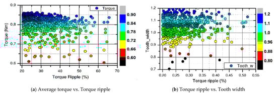
Figure 6.
Torque ripple Pareto-fronts.
A further study is performed to assess the influence of the flux barriers design on the average torque (Figure 7).
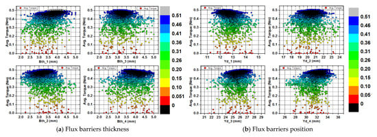
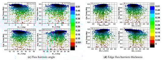
Figure 7.
Sensitivity analysis for different flux barriers geometrical parameters and their impact on average torque.
The obtained electromagnetic torque vs. speed characteristic for the pre-design and the optimized design of the SynRM topologies are shown in Figure 8a. Compared to the initial design, after running the optimization loop, a significant increase of more than 20% is reported in terms of torque. Rather noteworthy is that not only values in the constant torque region are higher, but also those above the base speed.
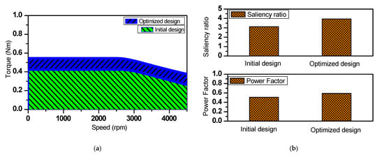
Figure 8.
(a) Torque vs. Speed characteristic—plotted area of the initial and optimized design. (b) Saliency ratio and power factor comparison.
4. FE Electromagnetic Analysis for Performance Comparison
Due to their strongly non-linear magnetization characteristics, all the field calculations are performed based on the FE models—mostly 2D (series of magnetostatic computations) unless otherwise mentioned.
4.1. Workflow and the Reference Machine
In the first step, the eight motor topologies both in CW and DW configuration (four of each) are designed while keeping the same electrical (i.e., input power) and geometrical parameters (i.e., outer diameter , and the length on Z-axis ,) in respect to the reference machine, see Figure 9 and Table 2. In respect to the later, important quantities and ratios i.e., average torque and torque ripple as well as, speed-torque/efficiency characteristics and power to weight ratio are analyzed.

Figure 9.
Cross-section of the analyzed PMSM-spoke design.
Table 2.
Performance comparison of the considered design with different slot/pole combination.
4.2. Design of SynRM with Concentrated Windings
The four analyzed topologies having different slot/pole combinations are shown in Figure 10. For a fair comparison, each of the four cross-sections is optimized for average torque and torque ripple, as explained in Section 3. Both the stator and the rotor lamination (including the number of flux barriers and their shape design) are optimized to meet the maximum saliency ratio. The obtained results, when assuming the specified current excitation and maximum allowed axial length, are summarized in Figure 11a,b—see also Table 2. It can be seen that the 12/4 design has the highest average torque while the 9/6 one exhibits the lowest one. As already explained in Section 2, increasing the number of poles further worsens the results (efficiency and saliency ratio), due to higher magnetizing current that is needed [9]. In terms of relative torque ripple (ratio between average and peak-to-peak values) the 9 slots 4-pole design has the lowest value (i.e., 24%) and the 6 slots 4-pole topology the highest one (i.e., 96%).
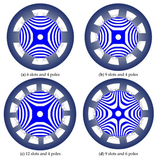
Figure 10.
Cross section of the analyzed SynRMs.
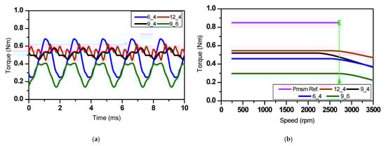
Figure 11.
Electromagnetic torque waveforms (a) and torque vs. speed for rated current limit (b) for CW-SynRMs.
The torque versus speed characteristic is computed using FE-obtained inductances and electromagnetic torque. At rated current, the machine speed is increased (at constant field weakening gamma angle) until the voltage limit is reached (at base speed). Following that at each speed point the optimal ratio between d- and q-currents is calculated (up to the maximum considered speed value). From Figure 12 it can be seen that the power factor is directly proportional to the machine’s saliency ratio. For the considered CW topologies, at base speed, the power factor is ranging between 0.4 and 0.64, the highest value being reported for the 12 slots 4-pole topology, which has also the highest saliency ratio (i.e., 3.9) and thus efficiency. The rather modest saliency ratio of CW-SynRM, compared to DW-SynRM can be explained by the higher stator leakage inductance [9].
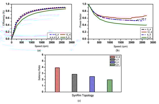
Figure 12.
Calculated efficiency (a), power factor (b) vs. speed and saliency ratio (c), at rated current for CW-SynRMs.
4.3. SynRM Design with Distributed Windings
Similarly, as for CW-SynRM, hereafter four DW-SynRM designs are analyzed, see Figure 13. Three of them have four poles, whereas for the CS with 27 slots a six poles rotor variant is chosen. Compared to the CW case, thanks to the sinusoidally distributed winding, the shape of the MMF in the air gap has a spectrum with fewer harmonics, leading to a sinusoidal field and thus a higher fundamental winding factor, resulting in higher average torque and lower torque ripple.
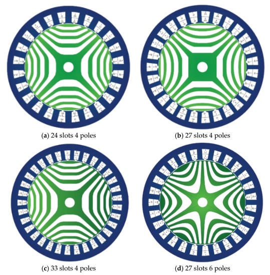
Figure 13.
Cross sections of the analyzed DW-SynRMs.
For each of the four CSs an optimal design is selected out of the Pareto-front. The waveforms of the torque obtained using FE-magnetostatic analysis are shown in Figure 14a, and the peak torque vs. speed characteristic in Figure 14b. As expected, DW-SynRM has a higher torque and lower torque ripple than its CW counterpart. Noteworthy is that not all DW CSs show superior characteristics as e.g., the 27 slots six pole design has an average torque similar to the nine slots six pole CW-design (i.e., 0.35 Nm) demonstrating once again that, given the power class and size, a higher number of poles is rather detrimental than favorable.
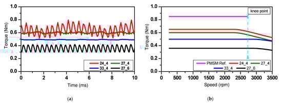
Figure 14.
Electromagnetic torque waveforms (a) and torque vs. speed for rated current limit (b) for DW-SynRMs.
Summarizing the results shown in Figure 14a, the 24 slots four pole design has the highest average torque (i.e., 0.64 Nm), but also the highest ripple (i.e., 43%). In terms of the later, the 33 slots four pole topology with c. 2% performs at best, but it has 23% less average torque compared to the previous design. Among all four CSs, the 27 slots four pole one is the best trade-off with an average torque of 0.6 Nm and a torque ripple content of 6%.
The speed dependent variations of torque, efficiency and power factor are shown in Figure 14b and Figure 15a,b, respectively. Excepting the six poles topology with c. 80%, all other designs have around 85% efficiency. The power factor shows a similar behavior.
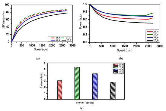
Figure 15.
Calculated efficiency (a), power factor (b) vs. speed and saliency ratio (c), at rated current.
By analyzing the results given in Table 2, it can be concluded that the 12 slots four pole CW and 27 slots four pole DW designs have the minimum torque ripple, the maximum torque capability and power factor. Therefore, they are selected for further investigations and finally prototyped.
4.4. Re-Optimization Process Including Manufacturing—Compatibility Rules
Especially for less-established motor topologies, in the early design stage not all the limitations imposed by the manufacturing process are known. Therefore, as soon as these limitations become clear, a late-stage re-optimization (a fine-tuning) of the design must be performed.
4.4.1. Problem Formulation for the Re-Optimization
To highlight the massive impact of the manufacturing constraint (a filling factor below 0.45), a sensitivity analysis is performed having two essential stator parameters, namely the tooth thickness T_Th0 and the tooth height T_Hs1 as DoFs. As expected, the torque increases with the tooth and back iron thickness, finding the value of the reference machine (shown in Figure 16a). However, the shrinking of the slot means that the filling factor exceeds the preset 0.45 as it can be noticed from Figure 16b, which, obviously is not acceptable.
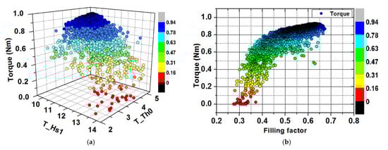
Figure 16.
Stator parameters variation (a) filling factor optimization (b).
To compensate for this limitation, during this optimization loop, the motors can exceed the specified length and they can draw more current. The outer diameter and battery voltages are still used as constraints. Using the same algorithms and workflows as already presented in Section 3, and considering the manufacturing-imposed constraints, the two designs are re-optimized. The predominant changes are on the stators side and winding as it can be seen from Table 3 and Figure 17. Furthermore, one can observe the increase in length from 18 mm to 26 mm for the 12 slots four pole topology. Finally, for the DW-design, the optimization algorithm increased the current to the detriment of the stack length which remained the same as for the initial design. The initially optimized SynRMs designs (green-dashed line) and the resized one (blue-dashed line) along with the prototyped stators are shown in Figure 18. It has to be mentioned that in order to fulfill the manufacturing process limitations, for the 12 slots four pole design the filling factor was decreased from 0.63 (initial value) down to 0.39, whereas for the 27 slots four pole structure from 0.54 to 0.4.
Table 3.
Best stator design obtained from the Pareto-front.
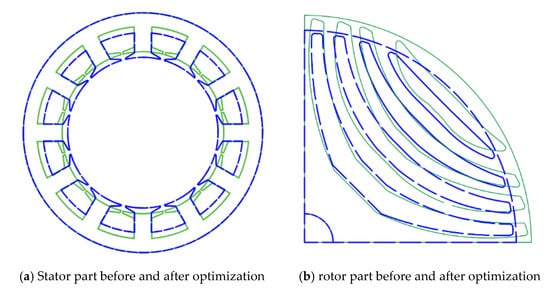
Figure 17.
SynRM geometries (a) stator and (b) rotor —before (green line) and after the optimization process (blue dotted line).
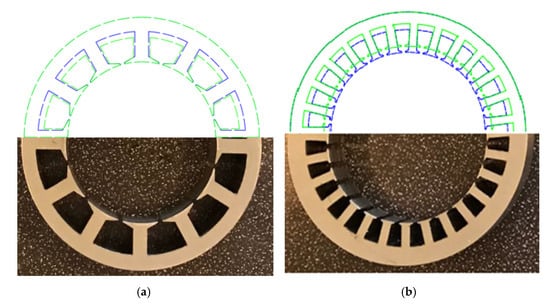
Figure 18.
SynRMs—before and after the optimization (a) the CW-design and (b) the DW-design.
4.4.2. Comparative Results of the Re-Optimized Design against the Specifications
Hereafter, the results obtained, with re-optimized designs while fully considering the limitations of the manufacturing process are compared with those of the PMSM.
As expected, allowing for more current and installation space, the machines fulfill the specifications in terms of torque-speed requirements. In Figure 19 the torque waveform of the PMSM is shown in magenta (average value 0.85 Nm, ripple 9%), that of the final CW-SynRM design in black (average value 0.92 Nm, ripple 38%) and that of the CW-SynRM design in red (average value 0.89 Nm, ripple 8%). In Figure 20 power factor, efficiency and saliency ration comparison are presented.
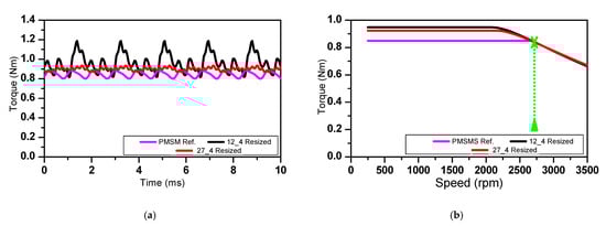
Figure 19.
Torque for re-optimized designs (a) and torque vs. speed characteristic (b).
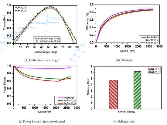
Figure 20.
Key performance indicators for both SynRMs.
To fulfill the specified operating point (0.85 Nm, 2700 rpm), the CW-SynRM needs 58% more AC-current and is 44% longer than the specified value (i.e., the PMSMs length), whereas the DW-SynRM has the same length but it requires 50%.
From the torque-speed characteristics shown in Figure 19b it can be seen that it is rather difficult to reach the specified base speed without over-sizing the machine (meaning lager torque value in the constant-speed zone). In the PMSM’s case, the torque is mainly produced by the magnet-generated flux (linked to the stator coils) and the saliency ratio is rather negligible. Thus, small adjustments of the torque-speed characteristic can be achieved by modifying the number of turns or the stack length. However, doing the same for a SynRM could undesirably alter the saliency due to the more pronounced non-linearity of the magnetic circuit (i.e., large variations of the ratio with the supply current).
4.4.3. Active Material Cost and Weight
Besides the performance, the weight and the cost of active materials are important driving forces when it comes to decision making process for an electrical machine. Therefore, in Table 4 a side-by-side comparison in terms of weight of active materials and their costs is realized for reference PMSM, CW-SynRM and DW-SynRM. For that, a net cost of 6.5 €/kg, 4 €/kg and 1 €/kg is considered for magnet, copper, and lamination material, respectively.
Table 4.
Active material weights and their costs.
The magnets are rather expensive materials, the SynRMs have a magnet-free structure, yet the PMSM’s active materials total costs are lower, when all motors are designed to fulfill the same torque-speed characteristic. On one hand, this is explained by the very low cost of the magnets used for the PMSM (ferrite-type with remanence around 0.4 T); they have a comparable cost with copper, which is heavily used in the SynRMs. On the other hand, one has to resort to oversizing for SynRMs to fulfill the specified torque-speed characteristic. Nevertheless, this difference could be smaller when considering additional costs associated with the manufacturing process, as for PMSM some extra steps are necessary (e.g., the whole logistic related to the magnets, their magnetization and insertion into the rotor stack process, protection against corrosion—if the case, etc.).
5. Design Check—Rotor Dynamics
Prior to building the two SynRM experimental models, an FE-based structural analysis is performed to evaluate the rotor’s mechanical stress at double the rated speed to ensure enough safety. Assuming materials having the properties shown in Table 5, [24], the rotor stress, it’s deformation, and the safety factors are calculated for each CS.
Table 5.
Mechanical properties of M800-50A.
The purpose of the analysis is to ensure that the small segments of the rotor (i.e., the tangential ribs linking its structure) are not loaded above the yield point. When the rotor is turning at given speed (5400 rpm in this particular study), the stress caused by the centrifugal forces acting on the rotor leads to the deformation of the lamination. Furthermore, depending on the operating point, the radial forces (obtained with the FE-electromagnetic analysis, and applied on the rotor structure as a radial pressure), could have a significant contribution to the total deformation of the rotor stack.
The von-Mises stress is calculated at 5400 rpm and its distribution is shown Figure 21. The maximum value for the CW rotor structure is 232 MPa and for the DW one is 255 MPa, values which are below the limit imposed by the tensile strength of the lamination material (i.e., 300 MPa). This ensures enough safety, considering that the operating point where the motor is driven in heathy operation is 2700 rpm. Not exceeding the yield point of the Si-Fe lamination, thus keeping the deformation of the material in the elastic region is mandatory for safe operation. However, this is not the only important condition: the absolute value of the deformation is equally important as due to this, variations of the air gap, with unwanted effects on the electromagnetic torque and its ripple, are to be expected. Also, due to the lack of radial ribs, for this case the maximum deformation is 19.7 μm (for CW-rotor), representing 3.8% from the air gap width. For verification purposes, for the same machine, at 2700 rpm the maximum local deformation is −9 μm (c. 2% from the air gap), see Figure 22.
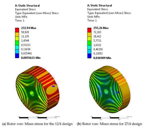
Figure 21.
von-Mises stress at 5400 rpm.
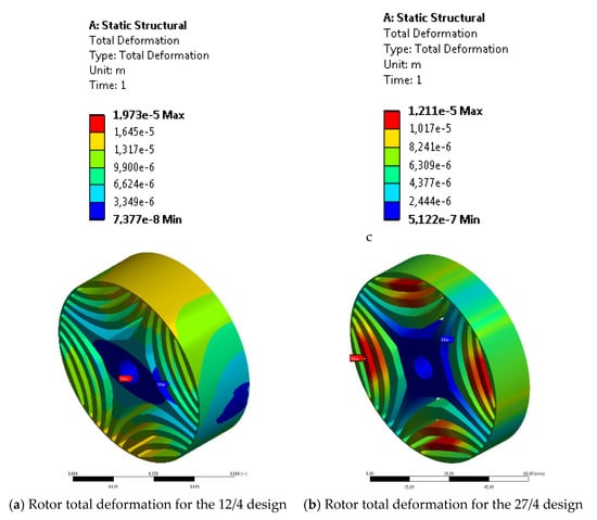
Figure 22.
Total deformation FE-structural analysis at 5400 rpm.
6. Experimental Validation
The two SynRMs presented in Section 4.4.2 were prototyped and their experimental testing is presented hereafter. For comparison purposes, the reference PMSM is tested under the same conditions and is built into the same housing as the SynRMs. Furthermore, a two-pole resolver, providing the rotor position detection signals through a RS232 port connection, is attached on the load-free side of the shaft, outside of the motors housing for all three investigated motors.
6.1. Prototype—Assembly and Manufacturing
Figure 23 shows an exploded view of the 3D CAD model of the CW-SynRM, where the individual parts along with corresponding sub-assemblies can be seen.
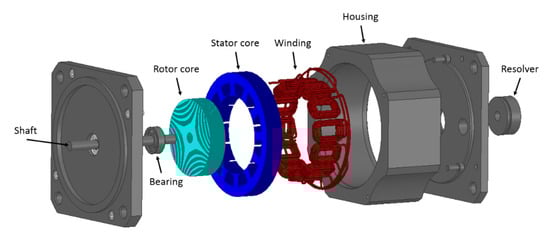
Figure 23.
3D CAD model of CW-SynRM.
The stator and rotor stacks obtained after gluing together the laser-cut lamination are shown in Figure 24.
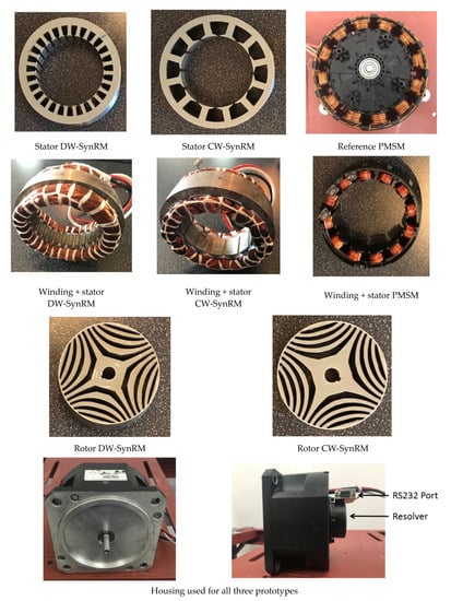
Figure 24.
Manufactured parts and sub-assemblies for all machines under study.
6.2. Brief Description of the Test-Bench
The experimental characterization of the three low-voltage machines up to their rated working point (0.85 Nm, 2700 rpm) is performed on the test-bench shown in Figure 25. As mechanical load, both the fan (from the reference system) and another load machine are used. Current, torque and speed are acquired for further post-processing and the field-oriented control is implemented using a dSpace MicroLabBox platform.
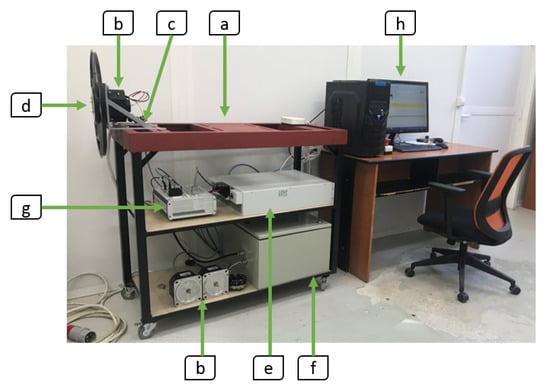
Figure 25.
Test bench for measurements with fan.
The test-bench shown in Figure 25 consists of: (a) fixation plate, (b) machine under test (MUT), (c) MUT fixation frame, (d) mechanical load (cooling fan), (e) AC/DC variable power supply, (f) 3-phase power converter, (g) dSpace Micro LabBox, (h) Control Desk.
6.3. Measured Performance Results
6.3.1. Dynamic Measurements (Ramp-Up to the Rated Point)
For the first set of tests, the original fan is used as load. It requires a torque, which is proportional to the square of rotational speed (Figure 26). The torque is estimated as a function of speed as follows:
with is the fan constant, n the speed (in rpm) and T the torque (in Nm).
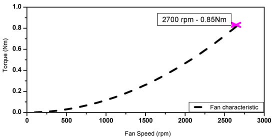
Figure 26.
Torque-speed characteristic of the used fan.
The estimated torque-speed characteristics based on the measured results are given in Figure 27. In terms of maximum speed point reached by each motor, unlike the PMSM, a difference of −14% and −28% can be seen for the DW-SynRM and CW-SynRM, respectively.
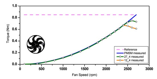
Figure 27.
Torque vs. speed characteristic (with the fan as load).
6.3.2. Steady-State Measurements (in One Operating Point)
Since, at specified voltage, the two designs cannot reach the operating point for which they were designed (i.e., 0.85 Nm @2700 rpm), two further measurements are performed. At first, the maximum speed that can be reached when the load torque is set to 0.85 Nm is identified, and following that, the maximum torque that can be produced when turning at 2700 rpm. For this set of measurements, a DC machine is used as mechanical load and the test-bench, shown in Figure 28, was equipped with a torque sensor. In both considered scenarios, and for both SynRMs the currents, phase voltage and mechanical torque are measured, and the results are compared against the FE-obtained ones.
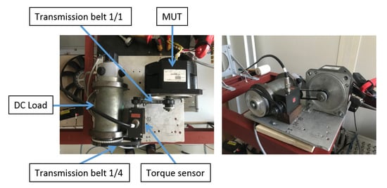
Figure 28.
Test bench with DC-load for steady-state measurements in discrete working points.
- (A)
- Measurements at constant load torque (0.85 Nm)
When operating under a load of 0.85 Nm, the maximum speed that can be reached by the CW-SynRM is 2000 rpm, whereas a value of 2200 rpm is obtained for the DW-SynRM. The torque waveforms are shown in Figure 29b and Figure 30b for the CW-SynRM and DW-SynRM, respectively.
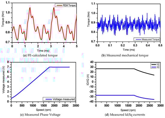
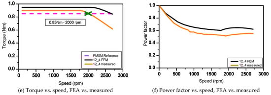
Figure 29.
FEA-obtained results vs. measurements for CW-SynRM.

Figure 30.
FEA-obtained results vs. measurements for DW-SynRM.
In the later, the dynamic effects of the magnetic field on torque are neglected, meaning that the speed has no effect of the torque waveform. The calculated value of the average torque matches the measured one quite well, but the measured torque ripple is about 50% lower than the calculated one. This can be partially explained by the inaccuracy of torque transducer at low measured values, as its ratings are at 20 Nm and the sensitivity and accuracy may affect the results at low levels under its rated torque. The device technical specifications indicate a ± 0.1% error at rated torque (20 Nm ± 0.02 Nm). Another potential source of error is the neglect of the previously mentioned dynamic effects. Finally, part of this can be attributed to the tolerances-induced variations of the air gap and the lamination BH curve.
Measured torque and power factor-speed characteristic were drawn based on acquired quantities at discrete speed points values and compared with the FE-obtained ones (see Figure 29e,f and Figure 30e,f).
- (B) Measured at constant speed (2700 rpm)
Unlike the previous case when the motor has a constant load and its speed is increasing until the point where it cannot hold the load anymore, in this case the speed is maintained at 2700 rpm and the load torque is increases incrementally, until the MUT starts losing its speed. In this way, the deviation to the specified value of 0.85 Nm can be determined. The measured results along with a comparison with the FE-calculated ones is given in Figure 31. In terms of average torque, this measurements scenario only confirms the deviations that were already obtained in Section 6.3.1 (i.e., −14% for the DW-SynRM and −28% for the CW-SynRM)—see Figure 31a,b. Furthermore, similar to section A, more points are measured discretely along the torque-speed curve, see Figure 31c,d and the efficiencies are calculated, see Figure 31e,f. The discrete measured working points along with the corresponding FE-based calculations are shown in Table 6 and Table 7.
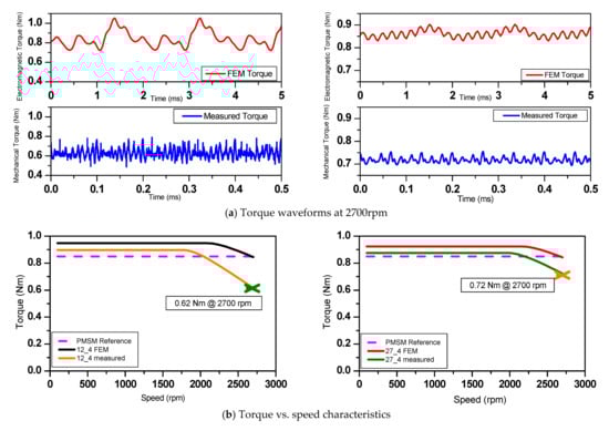
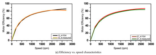
Figure 31.
FE-obtained vs. measured results (left 12/4 SynRM, right 27/4 SynRM).
Table 6.
Summary of the CW-SynRM measured operating points.
Table 7.
Summary of DW-SynRM measured operating points.
7. Conclusions
In this paper a comparative study between the CW-SynRM and DW-SynRM was realized for a low-power, low-voltage CFM used in automotive. Various motor topologies both in CW and DW configuration, having different number of rotor poles and stator slots were designed and optimized having as requirements and specifications the datasheet of FSCW-PMSM. The latter is the standard motor used for such applications, being already implemented in different projects in series. The relative differences between all three motor types are highlighted both at numerical and experimental level.
For that eight SynRM topologies (CW: 6/4, 9/4, 12/4, 9/6; DW: 24/4, 27/4, 33/4, 27/6) are designed and optimized using multi-objective particle swarm-based technique. As DoFs, various geometrical parameters are used. In the first designed stage, all motors were designed while keeping the same input power, outer diameter, and axial length as for the reference machine. In respect to the later, important quantities and ratios i.e., average torque and torque ripple as well as, speed-torque/efficiency characteristics and power to weight ratio as well as the costs and weights of the active materials were analyzed. Scattered plots are used to find the best trade-off between electromagnetic objectives and mechanic constraints.
The following conclusions can be drawn for the CW topologies:
- the 12/4 design has the highest average torque,
- the 9/6 design exhibits the lowest one,
- the 9/4 design has the lowest value torque ripple (i.e., 24%),
- the 6/4 topology the highest one (i.e., 96%),
- at base speed, the power factor is ranging between 0.4 and 0.64,
- the 12/4 topology has the highest power factor and also the highest saliency ratio (i.e., 3.9),
- it has also the highest efficiency.
As for the DW topologies, the following can be concluded:
- the 24/4 design has the highest average torque (i.e., 0.64 Nm),
- it has also the highest ripple (i.e., 43%),
- the 33/4 topology with c. 2% has the lowest torque ripple,
- it has also 23% less average torque compared to the 24/4 design,
- the 27/4 topology is the best trade-off with an average torque of 0.6 Nm and a torque ripple content of 6%,
- excepting the six poles topology with c. 80%, all other designs have around 85% efficiency.
Two motor topologies (i.e., the 12 slots four pole CW and 27 slots four pole DW) were chosen and following a late-stage redesign to account for manufacturing constraints, the final dimensions were defined. Subsequently, by means of FE-based structural analysis, these two designs were validated in terms of the mechanical integrity of the rotor structure and then prototyped.
The two prototyped SynRMs were validated experimentally using as mechanical load both the fan (from the reference system) and another load machine. For comparison purposes, the reference PMSM was tested under the same conditions. During the first testing stage, with the original fan as load, deviations of −14% and −28% were reported for the DW-SynRM and CW-SynRM, respectively, when comparing the maximum reached speed against the specifications. This can be partially explained by the not very well optimized control as well as due to the tolerances-induced variations of the air gap and the BH curve of the lamination. Similar deviations were reported also during the second set of tests, when a DC machine was used as mechanical load, and the motors were driven in discrete operating points in steady-state along their peak torque-speed characteristic.
Author Contributions
All the authors contributed substantially to the paper. Conceptualization, A.-C.P. and F.P.P.; methodology, F.P.P. and A.-C.P.; software, F.P.P.; validation, F.P.P., A.-C.P. and C.M.; formal analysis, F.P.P.; investigation, F.P.P.; writing—original draft preparation, F.P.P.; writing—review and editing, A.-C.P.; supervision, C.M.; project administration, C.M.; funding acquisition, C.M. All authors have read and agreed to the published version of the manuscript.
Funding
This work was supported by a grant of the Romanian Ministry of Research and Innovation, CCCDI—UEFISCDI, project number PN-III-P1-1.2-PCCDI-2017-0776/No. 36 PCCDI/15.03.2018, within PNCDI III.
Institutional Review Board Statement
Not applicable.
Informed Consent Statement
Not applicable.
Data Availability Statement
Not applicable.
Conflicts of Interest
The authors declare no conflict of interests.
References
- Kazakbaev, V.; Prakht, V.; Dmitrievskii, V.; Ibrahim, M.N.; Oshurbekov, S.; Sarapulov, S. Efficiency analysis of low electric power drives employing induction and synchronous reluctance motors in pump applications. Energies 2019, 12, 1144. [Google Scholar] [CrossRef]
- Ozcelik, N.G.; Dogru, U.E.; Imeryuz, M.; Ergene, L.T. Synchronous reluctance motor vs. Induction motor at low-power industrial applications: Design and comparison. Energies 2019, 12, 2190. [Google Scholar] [CrossRef]
- Donaghy-Spargo, C.M. Synchronous Reluctance Motors with Fractional Slot-Concentrated Windings. Ph.D. Dissertation, Newcastle University, Newcastle upon Tyne, UK, 2016. [Google Scholar]
- Spargo, C.M.; Mecrow, B.C.; Widmer, J.D. Higher pole number synchronous reluctance machines with fractional slot concentrated windings. In Proceedings of the 7th IET International Conference on Power Electronics, Machines and Drives (PEMD 2014), Manchester, UK, 8–10 April 2014. [Google Scholar]
- Kostko, J.K. Polyphase reaction synchronous motors. J. Am. Inst. Electr. Eng. 1923, 42, 1162–1168. [Google Scholar] [CrossRef]
- Haataja, J. A Comparative Performance Study of Four-Pole Induction Motors and Synchronous Reluctance Motors in Variable Speed Drives. Ph.D. Thesis, Lappeentanta University of Technology, Lappeenranta, Finland, 2003. [Google Scholar]
- Pop, A.C.; Piglesan, F.P.; Martis, R.; Vintiloiu, I.; Martis, C. First Insights on the Electromagnetic Design of Axial-Flux Synchronous-Reluctance Maschine. In Proceedings of the IECON 2018-44th Annual Conference of the IEEE Industrial Electronics Society, Washington, DC, USA, 21–23 October 2018; pp. 5702–5709. [Google Scholar]
- Barcaro, M.; Bianchi, N.; Magnussen, F. Permanent-magnet optimization in permanent-magnet-assisted synchronous reluctance motor for a wide constant-power speed range. IEEE Trans. Ind. Electron. 2011, 59, 2495–2502. [Google Scholar] [CrossRef]
- Moghaddam, R. Synchronous Reluctance Machine (SynRM) in Variable Speed Drives (VSD) Applications. Ph.D. Thesis, Stockholm University, Stockholm, Sweden, 2011. [Google Scholar]
- Pop, F.P.; Popa, D.C.; Marţiş, R.; Marţiş, C.; Pop, A.C. Comparative analysis of rare earth-less electrical machines for 48V automotive cooling fan applications. In Proceedings of the 2017 14th International Conference on Engineering of Modern Electric Systems (EMES), Oradea, Romania, 1–2 June 2017; pp. 180–183. [Google Scholar]
- Bianchi, N.; Bolognani, S.; Bon, D.; Dai Pre, M. Rotor flux-barrier design for torque ripple reduction in synchronous reluctance and PM-assisted synchronous reluctance motors. IEEE Trans. Ind. Appl. 2009, 45, 921–928. [Google Scholar] [CrossRef]
- Niazi, P.; Toliyat, H.A.; Goodarzi, A. Robust maximum torque per ampere (MTPA) control of PM-assisted SynRM for traction applications. IEEE Trans. Veh. Technol. 2007, 56, 1538–1545. [Google Scholar] [CrossRef]
- Moghaddam, R.R.; Gyllensten, F. Novel high-performance SynRM design method: An easy approach for a complicated rotor topology. IEEE Trans. Ind. Electron. 2013, 61, 5058–5065. [Google Scholar] [CrossRef]
- Vartanian, R.; Toliyat, H.A. Design and comparison of an optimized permanent magnet-assisted synchronous reluctance motor (PMa-SynRM) with an induction motor with identical NEMA Frame stators. In Proceedings of the 2009 IEEE Electric Ship Technologies Symposium, Baltimore, MD, USA, 20–22 April 2009; pp. 107–112. [Google Scholar]
- Taghavi, S.; Pillay, P. A comparative study of synchronous reluctance machine performance with different pole numbers for automotive applications. In Proceedings of the IECON 2014-40th Annual Conference of the IEEE Industrial Electronics Society, Dallas, TX, USA, 29 October–1 November 2014; pp. 3812–3818. [Google Scholar]
- Staton, D.A.; Miller, T.J.E.; Wood, S.E. Maximising the saliency ratio of the synchronous reluctance motor. IEE Proc. B Electr. Power Appl. 1993, 140, 249–259. [Google Scholar] [CrossRef]
- Iga, Y.; Takahashi, K.; Yamamoto, Y. Finite element modelling of turbine generator stator end windings for vibration analysis. IET Electr. Power Appl. 2016, 10, 75–81. [Google Scholar] [CrossRef]
- López, C.; Michalski, T.; Espinosa, A.; Romeral, L. Rotor of synchronous reluctance motor optimization by means reluctance network and genetic algorithm. In Proceedings of the 2016 XXII International Conference on Electrical Machines (ICEM), Lausanne, Switzerland, 4–7 September 2016; pp. 2052–2058. [Google Scholar]
- Lee, J.-K.; Jung, D.-H.; Lim, J.; Oh, Y.J.; Lee, K.-D.; Lee, J. Rotor Open-Rib Design for Power Density Improvement in Synchronous Reluctance Motor. J. Magn. 2018, 23, 55–60. [Google Scholar] [CrossRef]
- Daldaban, F.; Cetin, E. Prototyping of Axial Flux Permanent Magnet Motors. In Proceedings of the 3rd International Symposium on Innovative Technologies in Engineering and Science, Valencia, Spain, 3–5 June 2015; Volume 13. [Google Scholar]
- Cavagnino, A.; Lazzari, M.; Profumo, F.; Tenconi, A. A comparison between the axial flux and the radial flux structures for PM synchronous motors. IEEE Trans. Ind. Appl. 2002, 38, 1517–1524. [Google Scholar] [CrossRef]
- Jara Montecinos, W.E. Axial Flux Permanent Magnet Machines Development of Optimal Design Strategies; Acta Universitatis Lappeenrantaensis: Lappeenranta, Finland, 2016. [Google Scholar]
- Armando, E.; Guglielmi, P.; Pellegrino, G.; Pastorelli, M.; Vagati, A. Accurate Modeling and Performance Analysis of IPM-PMASR Motors. IEEE Trans. Ind. Appl. 2009, 45, 123–130. [Google Scholar] [CrossRef]
- Mechanical Properties of M800-50A. Available online: http://www.steelnumber.com/en/steel_composition_eu.php?name_id=1935 (accessed on 18 October 2020).


Publisher’s Note: MDPI stays neutral with regard to jurisdictional claims in published maps and institutional affiliations. |
© 2021 by the authors. Licensee MDPI, Basel, Switzerland. This article is an open access article distributed under the terms and conditions of the Creative Commons Attribution (CC BY) license (http://creativecommons.org/licenses/by/4.0/).