Abstract
Currently, various types of superconducting power cables are being developed worldwide, and research and development of a tri-axial high-temperature superconducting (HTS) power cable are underway. The tri-axial HTS power cable reduces the amount of HTS wire due to its multilayer structure, has high current characteristics, and has less loss than other superconducting cables. However, since the radii of each phase are different, magnetic coupling makes it difficult to measure power loss and analyze performance. This paper presents the results of the design and performance analysis of a tri-axial HTS power cable. A prototype tri-axial HTS power cable was designed with a rated power of 60 MVA, a rated voltage of 23 kV and a length of 6 m, and was tested by cooling to 77 K with liquid nitrogen. We analyzed the performance of the tri-axial HTS power cable in normal conditions through a finite element method (FEM) simulation and experiment. The alternating current (AC) loss of the tri-axial HTS power cable was calculated using a FEM program based on the Maxwell equation, and the result was used to confirm the AC loss of the tri-axial HTS power cable prototype measured by the electrical measurement method. In conclusion, in the current test of a tri-axial HTS cable designed as 23 kV/60 MVA, the DC critical current was over 6000 A, the AC loss was approximately 0.24 W/m, and the simulation and analysis design values were satisfied. The results of this study will be effectively applied to commercial tri-axial HTS power cable development to be installed in a real power system. This means that the actual tri-axial HTS cable has sufficient capacity for rated current operation in the system where it will be applied, and the actual measurement of the cable loss can be applied as an important factor in the design of the cooling capacity of the entire superconducting cable, which consists of several kilometers.
1. Introduction
High-temperature superconducting (HTS) cables are being developed, and have the advantage of higher current densities as compared to conventional copper cables, as power demand increases worldwide [1]. HTS cables are being studied in a variety of structures for applications in high-capacity systems with low voltage and high current [2,3]. Especially in the case of coaxial-type HTS cable that consists of multiple layers of one axis, superconducting wires can be reduced because a self-balancing shielding layer is not necessary in three-phase equilibrium conditions, and thus it has a compact structure [4]. A tri-axial HTS power cable structure is determined by radius, pitch length, and winding direction [5]. This structure is composed by taking into account the cross-sectional area that is sufficient for fault current to flow, the insulation thickness according to the voltage level, and the amount of superconducting wire according to the rated current [6]. Parameters, such as pitch length and winding direction, which determine the structure of a tri-axial HTS power cable, affect the current distribution of the cable [7]. The different radii between each phase and layer cause a non-uniform current in the tri-axial HTS power cable [8]. The non-uniform current distribution consequently increases AC loss in the cable and also degrades cable performance. AC losses can be minimized with a uniform current distribution of each phase through proper structure design of the tri-axial HTS power cable [9,10].
This paper analyzes the cable performances through the design and fabrication of the 23 kV/60 MVA class tri-axial HTS power cable. In addition, the design and performance verification of the tri-axial HTS power cable was carried out through the production and measurement of laboratory scale 6-m-long prototype cable. The tri-axial HTS power cable has a four-layer structure using YBCO superconducting wire. Phase A consists of two layers to increase the operating current. The numerical, analysis-based, impedance balancing algorithm can iteratively calculate the pitch length and winding direction to minimize the unbalanced current. The AC loss of the designed tri-axial HTS power cable was simulated using the finite element method (FEM) based on the Maxwell equation and E-J superconducting characteristics, and the result was compared with the measured AC loss [11]. The characteristics of the tri-axial HTS power cable were measured using electrical methods, and the performances of the cables were evaluated by measuring the V-I characteristics and the AC losses of each phase of the superconducting layer [12]. For the tri-axial HTS power cable, the critical currents of each phase were measured under liquid nitrogen conditions at 77 K [13,14]. The measured AC loss of the tri-axial HTS power cable was 249 mW/m, which is similar to the calculated result obtained using the FEM program. The results of this study will be effectively applied to the development of commercial tri-axial HTS power cable which will be installed in a Korea Electric Power Corporation (KEPCO) system. KEPCO is promoting the first tri-axial HTS power cable system demonstration project in Korea, and for this purpose, it has established a demonstration site of a connection between the substation and the substation to transmit power. The purpose of this paper is to develop and verify the performance of initial prototypes reflecting the conditions of on-site system power capacity (23 kV/60 MVA) and HTS power cable systems for real-grid applications. The data through the design and experiment of this prototype cable will be used as an important factor for the design of the actual system rated current operation and the cooling capacity of the superconducting cable system.
2. Design of a Tri-Axial HTS Power Cable
2.1. Numerical Design of the Tri-Axial HTS Power Cable
Figure 1 shows the core structure of a 6-m-long tri-axial HTS power cable. The core of the cable consists of two layers of phase A to achieve a rated current capacity. In this paper, a concentric support made of glass fiber reinforced plastic (GFRP), instead of copper, was installed in the center of the cable core to allow for only the superconducting layer performance to be measured. The insulation layer between each phase of the cable was designed to maintain the voltage level. The detailed structures and specifications of the tri-axial HTS power cable are shown in Table 1 and Table 2. Design items are numerically designed and structurally analyzed based on the radius, voltage, current, length, etc.
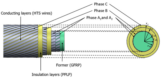
Figure 1.
Structure of the 6-m-long, tri-axial high-temperature superconducting (HTS) power cable.

Table 1.
Structures of the prototype tri-axial HTS power cable model.
Table 2.
Specifications of the tri-axial HTS power cable model.
The numerical design goal of the tri-axial HTS power cable is to achieve uniform current distribution in each layer. To calculate the current distribution in each layer of a tri-axial HTS power cable, the resistance, inductance, and mutual inductance must be taken into account. Figure 2 shows the electrical equivalent circuit diagram of the tri-axial HTS power cable.
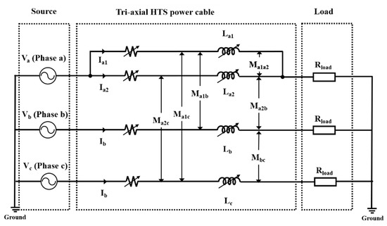
Figure 2.
Electrical circuit diagram of the tri-axial HTS power cable.
The inductance and mutual inductance of the electrical equivalent circuit are calculated as shown in Equations (1) and (2). The impedance matrix is derived from the equivalent circuit connected to the source and the load, as shown in Figure 2 using Equations (1) and (2). The current distribution in each phase and layer is determined by the iterative calculation of the impedance matrix of Equation (3) with a combination of pitch length and winding direction. The iterative calculation of the impedance matrix is performed by applying an impedance matching algorithm that satisfies the set current value in each layer, and Figure 3 shows a flow chart of the impedance matching method [15,16].
where Li is the self-inductance of the i layer, Mij is the mutual inductance between the i layer and j layer, ri is the radius of the i layer, rj is the radius of the j layer, μ0 is the magnetic permeability of free space, D is the distance between the cable center and the outmost surface, ai is the winding direction of clockwise, aj is the winding direction of counter-clockwise, Lpi is the pitch length of the i layer, and Lpj is the pitch length of the j layer.
where Vi is the voltage of the i layer, Ii is the current of the i layer, j is the imaginary unit, ω is the angular frequency, Li is the self-inductance of the i layer, Mij is the mutual inductance between the i layer and j layer, and Rload is the load resistance.
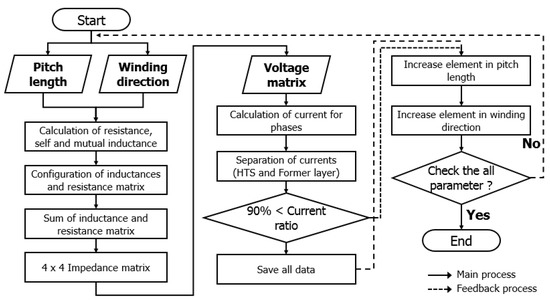
Figure 3.
Block diagram for impedance matching of the tri-axial HTS power cable.
The tri-axial HTS power cable was analyzed under the rated current load condition. The impedance matching process was used to select one case suitable for a combination of more than 10,000 pitch lengths and winding directions as shown in Figure 3. Table 3 shows the current distribution calculation results, and the current distribution of each phase was uniform. In addition, it was calculated that about half of the rated current flows in each layer in phase A have two layers.
Table 3.
Results of current distribution in the tri-axial HTS power cable.
2.2. FEM Anaysis of the Tri-Axial HTS Power Cable
The structure of the tri-axial HTS power cable with uniform current distribution obtained by mathematical calculations was designed. The AC loss of the superconducting layer of the tri-axial HTS power cable that occurred during steady state operation was analyzed using a FEM analysis program. Figure 4 shows a 2D AC loss analysis model of a tri-axial HTS power cable with a 1/5 scale model taken to reduce overall analysis time.
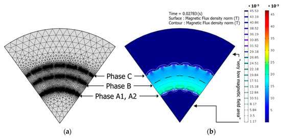
Figure 4.
Configuration of the FEM model for loss analysis: (a) the mesh mode used for calculations; (b) the calculated magnetic field distribution.
The governing equation for the tri-axial HTS power cable AC loss analysis applies Maxwell’s equations, including Faraday’s law and Ampere’s circuital law, as shown in Equations (4) and (5). In addition, E-J characteristics with superconducting nonlinear characteristics, as shown in Equation (6), are reflected in each phase’s superconducting wire [17,18].
where μ is the magnetic permeability, t is the time, H is the magnetic field, E is the electric field, Ec is the critical electric field, J is the current density, Jc is the critical current density, and n is the n-value.
Figure 5 shows the results of the AC loss analysis of each phase of a tri-axial HTS power cable at a rated current of 2200 Apeak. The superconducting layers are adjacent to each other, resulting in a large loss of phases A1 and A2, where a large amount of vertical magnetic field acts on the superconducting wire and low B and C phase losses, relatively far from the magnetic field.
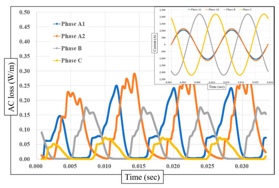
Figure 5.
AC loss of the FEM model for loss analysis (at 2200 Apeak).
Figure 6 shows the single-phase AC loss results obtained by FEM analysis for the tri-axial HTS power cable. The analysis results show that the AC losses are 73, 113, and 74 mW/m, depending on the phase from A to C at the rated current, and the total loss is 260 mW/m. The results of the single-phase AC losses obtained by FEM analysis were compared with the measurement result of a real-scale tri-axial HTS power cable.
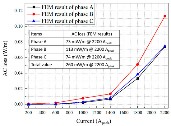
Figure 6.
AC loss analysis results for single-phase currents of the tri-axial HTS power cable.
3. Measurement Results and Discussion
A 6-m-long of 23 kV/60 MVA-class tri-axial HTS power cable consisting of multilayer HTS wire and a GFRP support was fabricated to evaluate the performance of the cable. The conductors of each phase are spirally wound on the support of the GFRP, and between each layer, are laminated with insulators of polypropylene-laminated paper, which considers isolation voltage level. Normally, current leads are connected at both ends of the cable to supply current to each phase. In the case of the tri-axial HTS power cables, one end consisted of a three-phase short circuit to reduce contact resistance losses. Figure 7 shows the fabricated tri-axial HTS power cable.
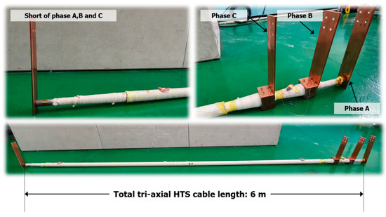
Figure 7.
Six-meter-long 23 kV/60 MVA-class tri-axial HTS power cable.
Figure 8 shows the algorithm of the DC-critical current measurement. A four-terminal method for voltage and current measurement of HTS cables was used. The critical current of the tri-axial HTS power cable was determined by the V-I characteristics of each phase. The voltage value for determining the critical current value was defined based on 1 μV/cm [19,20].
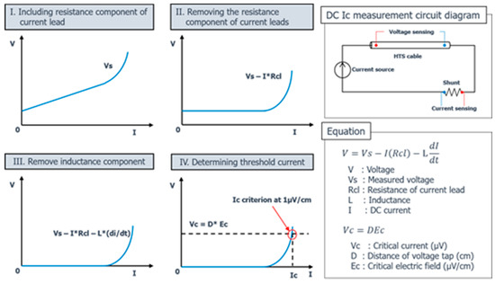
Figure 8.
Algorithm of the DC-critical current measurement.
Figure 9 shows the hardware configuration concept of the DC Ic measurement for the 6-m-long tri-axial HTS power cable. The DC power supply supplies current to the cable sample, the shunt resistor measures the current, and the voltage tap on both ends of the cable measures the voltage. The control part collects these two signal data to obtain a critical current value for the critical voltage. The critical current of each phase is measured independently.
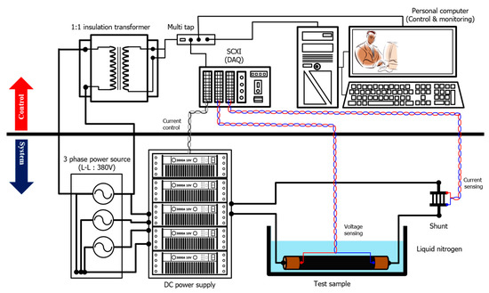
Figure 9.
Configuration concept of the DC Ic measurement for the 6-m-long tri-axial HTS power cable.
The critical current and AC loss measurements of the cable were carried out at cryogenic conditions with 4–5 h of cooling at 77 K in liquid nitrogen. As shown in Figure 10, the measurement configuration concept shown in Figure 9 was implemented through actual cables and measurement equipment.
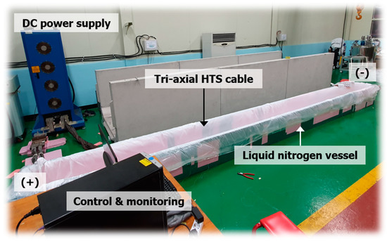
Figure 10.
Real configuration of the DC Ic measurement for the 6-m-long tri-axial HTS power cable.
The measured critical currents for phase B and phase C were 6194.9 A and 7308.1 A, respectively. In addition, phase A was measured until 7308.1 A. Figure 11 shows the critical current measurement results for each phase of the tri-axial HTS power cable. It can be seen that the measured critical current is more than the design current value, and that the manufactured cable sample is stable.
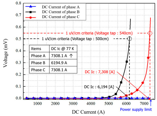
Figure 11.
DC current measurement result of the tri-axial HTS power.
Figure 12 illustrates the principle of AC loss measurement for superconducting cables. It can be seen that V0 and I0 are easy to measure with accurate volt-meters. However, Ɵ is very difficult to measure even if we use an accurate (expensive) lock-in amplifier. Very fast measurement methods should be applied to perform a precise integration process. The method using cancel coil is measured by resistance, which was canceled due to the influence of the voltage and magnetic field by self-inductance of the cable [21,22,23].
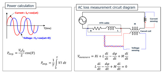
Figure 12.
Principle of AC loss measurement.
The tri-axial HTS power cable uses an electrical method to measure AC losses under single current conditions. Figure 13 and Figure 14 show the configuration of the AC loss measurement method of the tri-axial HTS power cable. The AC loss was measured for each phase through the voltage taps and the current sensor on A, B, and C, and the total cable loss according to the unit length was calculated [24,25].
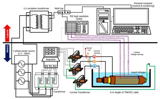
Figure 13.
Configuration concept of AC loss measurement for the 6-m-long tri-axial HTS power cable.
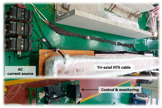
Figure 14.
Real configuration of AC loss measurement for the 6-m-long tri-axial HTS power cable.
The tri-axial HTS power cable is connected to both ends of the AC current source, and the voltage is measured by the signal wire attached to the cable. In addition, the current is measured by a current transformer. A cancel coil is used to remove the inductance component of the tri-axial HTS power cable. The purpose of this method is to remove the reactive component from the measured voltage to improve measurement accuracy. Figure 15 shows the AC loss measurement results for a single-phase current. The measured results show that the AC losses of each phase were 55, 72, and 122 mW/m at a rated current of 2200 Apeak, and the total AC loss of a single-phase current was 249 mW/m. The FEM simulation result of the tri-axial HTS power cable was 260 mW/m, which is similar to the total AC loss measurement result.
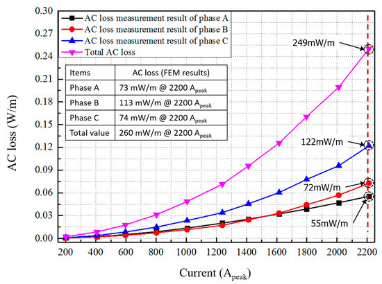
Figure 15.
Measurement results for AC loss of the tri-axial HTS power cable.
4. Conclusions
A 23 kV/60 MVA-class, tri-axial HTS power cable was designed, fabricated, and tested to evaluate the performance. The tri-axial HTS power cable has been designed in the proper structure by mathematical calculations and FEM analysis focusing on current balancing. Based on the designed structure, a 6-m-long of tri-axial HTS power cable was fabricated. The critical currents of each phase in the tri-axial HTS power cable were measured. As a result of the critical current measurement, the critical current value of each phase was measured to be over 6000 A, and it appears that it has sufficient performance for rated current operation in a 23 kV 60 MVA grid system. The measurement error of the AC loss was reduced by removing the reactive component of the voltage being measured on the tri-axial HTS power cable. The AC loss was measured for single-phase current from a 0 to 2200 Apeak operation range of the rated current. The total AC losses for single-phase current condition measured less than 250 mW/m. The measured AC losses were compared with the FEM model and were similar to the simulation results. The results of this study can also be used for future design and performance evaluation and verification of tri-axial HTS power cables with copper formers. The superconducting cable system that will be installed in an actual power transmission network consists of a superconducting cable, a joint box, a terminal box, and a cooling system. The AC loss (W/m) of the superconducting cable contributes significantly to the overall cooling capacity in a few km of superconducting cable system. In calculating the capacity of an expensive cryogenic refrigerator, the actual AC cable loss value has the advantage of ensuring stability of the capacity of the cooling system, and can be applied as a design factor to secure the system stability against the operating temperature of the superconducting cable. The results of this paper will provide important data for the tri-axial superconducting cable system that will be installed at the first real grid system site in Korea.
Author Contributions
Conceptualization, writing—original draft preparation and editing, analysis and interpretation, experiments, S.-J.L.; Writing—Original draft preparation, analysis and interpretation, experiments, S.Y.K.; Project supervision and administration, provided final approval of the version to publish, M.P.; Funding acquisition, agreed to be accountable for all aspects of the work in ensuring that questions related to the accuracy, D.W.; Funding acquisition, provided critical revision of the article, J.Y.; Funding acquisition and provided final approval of the version to publish, H.S.Y. All authors have read and agreed to the published version of the manuscript.
Funding
This work was funded by Korea Electric Power Corporation.
Conflicts of Interest
The authors declare no conflicts of interest.
References
- Li, Z.; Ryu, K.; Fukui, S.; Hwang, S.D.; Cha, G. AC Loss Measurement of a Short HTS Cable With Shield by Electrical Method. IEEE Trans. Appl. Supercond. 2011, 21, 1005–1008. [Google Scholar] [CrossRef]
- Lee, S.J.; Park, M.; Yu, I.K.; Won, Y.; Kwak, Y.; Lee, C. Recent Status and Progress on HTS Cables for AC and DC Power Transmission in Korea. IEEE Trans. Appl. Supercond. 2018, 28, 5401205. [Google Scholar] [CrossRef]
- Sytnikov, V.; Shutov, K.; Polyakova, N.; Fetisov, S.; Nosov, A.; Vysotsky, V. The AC Loss Analysis in the 5 m HTS Power Cables. IEEE Trans. Appl. Supercond. 2009, 19, 1706–1709. [Google Scholar] [CrossRef]
- Satoshi, F.; Takeshi, N.; Jun, O.; Mitsugi, Y.; Takao, S.; Osami, T. Analysis of AC Loss and Current Distribution Characteristics of Multi-Layer Triaxial HTS Cable for 3-Phase AC Power Transmission. IEEE Trans. Appl. Supercond. 2006, 16, 135–138. [Google Scholar]
- Hamajima, T.; Tsuda, M.; Yagai, T.; Monma, S.; Satoh, H.; Shimoyama, K. Analysis of AC Losses in a Tri-axial Superconducting Cable. IEEE Trans. Appl. Supercond. 2007, 17, 1692–1695. [Google Scholar] [CrossRef]
- Rabbers, J.J.; ten Haken, B.; ten Kate, H.H. Advanced ac loss measurement methods for high-temperature superconducting tapes. Rev. Sci. Instrum. 2001, 72, 2365–2373. [Google Scholar] [CrossRef]
- Zhu, J.; Zhang, Z.; Zhang, H.; Zhang, M.; Qiu, M.; Yuan, W. Electric Measurement of the Critical Current, AC Loss, and Current Distribution of a Prototype HTS Cable. IEEE Trans. Appl. Supercond. 2014, 24, 9500104. [Google Scholar] [CrossRef]
- Nassi, M. HTS prototype for power transmission cables: Recent results and future programmes. Supercond. Sci. Technol. 2000, 13, 460–463. [Google Scholar] [CrossRef]
- Lim, S.-H.; Yim, S.-W.; Hwang, S.-D.; Han, B.-S. Influence of pitch length and winding direction on four-layer HTSC power transmission cable with a shield Layer. IEEE Trans. Appl. Supercond. 2005, 15, 1735–1738. [Google Scholar] [CrossRef]
- Kim, S.; Sim, K.; Cho, J.; Jang, H.M.; Park, M. AC Loss Analysis of HTS Power CableWith RABiTS Coated Conductor. IEEE Trans. Appl. Supercond. 2010, 20, 2130–2133. [Google Scholar]
- Shinichi, M.; Naoyuki, A.; Kazuo, W.; Yasuhiro, I.; Nobuhiro, M.; Takao, M.; Toshiya, M.; Masayoshi, O.; Tetsutaro, N.; Kiyoshi, Y. Study on AC loss measurements of HTS power cable for standardizing. IOPsci. J. Phys. Conf. Ser. 2017, 897, 012021. [Google Scholar]
- Kim, J.H.; Kim, C.H.; Iyyani, G.; Kvitkovic, J.; Pamidi, S. Transport AC Loss Measurements in Superconducting Coils. IEEE Trans. Appl. Supercond. 2011, 21, 3269–3272. [Google Scholar] [CrossRef]
- Steffen, E.; Eduard, D.; Bruno, D.; Francesco, G.; Andrej, K.; Mark, S.; Severin, S.; Victor, Z.; Wilfried, G. New Experimental Method for Investigating AC Losses in Concentric HTS Power Cables. IEEE Trans. Appl. Supercond. 2015, 25, 5900105. [Google Scholar]
- Kazuhisa, A.; Hiroki, O.; Ryusuke, H.; Shigeki, S.; Kei, S.; Nobuhiro, M.; Tsutomu, K.; Takayo, H.; Masayuki, K.; Masataka, I. Design of 22-kV 10-kA HTS Triaxial Superconducting Bus. IEEE Trans. Appl. Supercond. 2016, 26, 5400604. [Google Scholar]
- Ashworth, S.P.; Nguyen, D.N. The electrical measurement of AC losses in a three-phase tri-axial superconducting cable. IOPsci. Supercond. Sci. Technol. 2010, 23, 095009. [Google Scholar] [CrossRef]
- Daisuke, M.; Naoki, T.; Norio, T. AC Loss Reduction of Coaxial Multi-Layer HTS Cable. IEEE Trans. Appl. Supercond. 2011, 21, 991–995. [Google Scholar]
- Tsuda, M.; Fujimoto, J.; Harada, N.; Hamajima, T. Thermal Analysis of Co-Axial Multi-Layered BSCCO HTS Power Cable. IEEE Trans. Appl. Supercond. 2004, 14, 642–645. [Google Scholar] [CrossRef]
- Tsuda, M.; Fujisawa, T.; Hiraoka, T.; Harada, N.; Yagai, T.; Hamajima, T. The Effective Current and Magnetic Field Distributions for Reducing AC Losses in Coaxial Multi-Layer HTS Transmission Cable. IEEE Trans. Appl. Supercond. 2006, 16, 1594–1597. [Google Scholar] [CrossRef]
- Kim, J.G.; Kim, A.-R.; Kim, D.; Park, M.; Yu, I.-K.; Cho, J.; Sim, K.-D.; Kim, S.; Lee, J.K.; Won, Y.-J. Development of a PSCAD/EMTDC Model Component for AC Loss Characteristic Analysis of HTS Power Cable. IEEE Trans. Appl. Supercond. 2010, 20, 1284–1287. [Google Scholar]
- Doan, A.N.; Stephen, P.A.; Robert, D.; William, C.; Steven, F. Measurements of AC Losses and Current Distribution in Superconducting Cables. IEEE Trans. Appl. Supercond. 2011, 21, 996–1000. [Google Scholar]
- Kazuhisa, A.; Kei, S.; Hideo, S.; Tasuku, K.; Noubuhiro, M.; Takayo, H.; Masayuki, K.; Masataka, I. Sudden short-circuit test of 22kV YBCO Triaxial superconducting cable. IEEE Trans. Appl. Supercond. 2018, 28, 5401104. [Google Scholar]
- Fetisov, S.S.; Zubko, V.V.; Zanegin, S.Y.; Nosov, A.A.; Ryabov, S.M.; Vysotsky, V.S. Study of the first russian triaxial HTS cable prototypes. IEEE Trans. Appl. Supercond. 2017, 27, 5400305. [Google Scholar] [CrossRef]
- Lee, S.J.; Yang, H.S. Recent Progress and Design of Three-Phase Coaxial HTS Power Cable in Korea. IEEE Trans. Appl. Supercond. 2019, 29, 5401205. [Google Scholar] [CrossRef]
- Kottonau, D.; De Sousa, W.T.B.; Bock, J.; Noe, M. Design Comparisons of Concentric Three-phase HTS Cables. IEEE Trans. Appl. Supercond. 2019, 29, 5420705. [Google Scholar] [CrossRef]
- Lee, S.J.; Sung, H.-J.; Park, M.; Won, D.Y.; Yoo, J.; Yang, H.S. Analysis of the Temperature Characteristics of Three-Phase Coaxial Superconducting Power Cable according to a Liquid Nitrogen Circulation Method for Real-Grid Application in Korea. Energies 2019, 12, 1740. [Google Scholar] [CrossRef]


© 2020 by the authors. Licensee MDPI, Basel, Switzerland. This article is an open access article distributed under the terms and conditions of the Creative Commons Attribution (CC BY) license (http://creativecommons.org/licenses/by/4.0/).