Abstract
In this paper, a novel combined radiation-convection floor heating system is shown. This study uses practice-based learning and investigated the thermal performance of a combined radiation-convection floor heating system with a water heat pump system by evaluating the thermal environment and energy consumption in an experimental test. A new method that analyzed the thermal performance of four different controls was developed and applied. The results of the surface temperature distributions demonstrated that Mode 1, which uses only convection, had the lowest floor temperature and was thus considered inappropriate for occupants who sleep on the floor. By contrast, Modes 2, 3, and 4 showed high floor surface temperatures as hot water was supplied to the radiant heating panel. The predicted mean vote (PMV) results suggest that radiant floor heating is not appropriate for intermittent heating. In other words, occupants of single residences who return home at night will experience a long period of discomfort if they heat their room using floor heating. In this case, Mode 1, which is convection heating, and Modes 3 and 4, which represent mixed modes provide a more comfortable environment. The difference between this experimental study and previous research is that four different control modes for a combined radiation-convection system were evaluated based on the same location of the equipment in a laboratory. Furthermore, we studied the long-term real-scale thermal performance using panel and energy consumption.
1. Introduction
1.1. Background and Objectives
In recent years, the issue of climate change has become a global concern. Developed countries, including Europe, are introducing new energy conservation measures to reduce greenhouse gases through climate change conventions. In South Korea, the government has mandated that all buildings be zero-energy by 2025. This has prompted the household sector to improve the energy efficiency of heating systems in single and multi-family homes.
Radiant heating systems are commonly used in South Korea and are operated in many other countries as well [1,2,3,4,5]. Radiant heating systems can provide a comfortable environment and low energy consumption. The radiant heating systems in South Korea are appropriate for the traditional sedentary lifestyle and are highly effective in ensuring continuous heating throughout the day [6]. However, recent demographic changes throughout South Korea have showed in a more active lifestyle and other cultural changes. For example, double-income families require intermittent heating because they only need heating during the night [7]. Moreover, the increasing number of single households has made intermittent heating and the introduction of more efficient heating methods a necessity. Existing radiant floor heating systems provide adequate thermal comfort; however, they cannot respond quickly to heating needs because they utilize the heat stored in the floor. In contrast, the convection heating method can rapidly reach suitable indoor temperatures because it only heats the air; however, its disadvantage is lower thermal comfort than that provided by radiant heating. Therefore, the simultaneous achievement of thermal comfort and rapid heating can be expected to improve the satisfaction of occupants.
Therefore, this study proposes a heating system that combines radiant floor heating with responsive convection heating. The comfort and energy consumption of the combined heating system were analyzed according to the operation method. We analyzed whether the proposed system is competitive with regard to thermal comfort and energy saving compared to existing convection heating and radiant floor heating methods.
All experiments were performed in a large-scale chamber. The indoor comfort levels in various operation modes were analyzed through the predicted mean vote (PMV) and indoor temperature distribution. The energy consumption of the total heating system was also measured.
1.2. Literature Review
Many previous studies have evaluated the thermal characteristics of radiation or convection heating systems using experimental tests and numerical simulations. Many studies have suggested improvements in the design and performance of these heating systems. Cho et al. investigated the thermal performance of a conventional Korean standard radiant floor heating system with polybutylene pipes (conventional heating system) and capillary tubes in an experimental test. The capillary type was the most responsive to intermittent operation and energy efficiency [8].
Sarbu et al. experimentally studied the energy efficiency of radiators and radiator floor heating systems in an office space. The radiator heating system showed 10% higher energy consumption and CO2 emission levels compared to the floor heating system under the same operating conditions; both systems provided acceptable thermal comfort [9]. Benakopoulos et al. investigated strategies for a radiator system in a multi-family building in Denmark to operate at small temperature differences. Two different flow strategies were analyzed as potential low-cost solutions for real-world apartments [10]. Shin et al. designed charts for predicting heat flux, the difference between maximum and minimum floor surface temperatures (DFST), and the maximum floor surface temperature (MFST) for a radiant floor heating system with pipes. The relationship between the heat flux and design parameters was investigated through a numerical simulation. Moreover, an additional chart was developed for a radiant floor heating panel without a floor covering, and for panels with linoleum and oak wood as floor coverings [11].
Other studies have used simulation modeling for radiant heating and cooling systems. Bojić et al. compared the thermal performances of floor, wall, ceiling, and floor-ceiling heating systems via the Energy-Plus program. Their results showed that the floor-ceiling heating method had the lowest energy consumption, CO2 emissions, and costs [12]. Strand et al. demonstrated transfer by heat conduction and developed a model for radiant heating and cooling within the Energy-Plus program [13]. Miriel et al. developed a simulation model via the TRNSYS software and used the experimental results for code verification and modeling ceiling panels used for heating and cooling [14]. Rahimi et al. investigated the substantive mechanism of the radiation from heat transferred using an under-floor heating system in steady conditions. The authors showed that the indoor air temperature distribution was also important in evaluating thermal comfort Moreover, by using the under-floor heating system, a more uniform indoor temperature was established [15]. Safizadeh et al. performed a survey on local thermal sensation and comfort based on a low-temperature radiant ceiling system with a window present. By applying a high insulation window, the temperature of the window had a minimal influence on the local thermal sensation at a relative ceiling surface temperature of 38 °C. However, these radiant ceiling systems were limited to the specific experimental test conditions [16]. By contrast, few experimental studies have compared the floor radiation system, the convection system, and a combined radiation-convection system under identical conditions for an objective evaluation of energy efficiency and thermal characteristics.
2. Materials and Methods
2.1. Methods
The purpose of this study is to evaluate the performance of a combined radiant-convection floor heating system through experimental measures. The key performance indexes were indoor thermal comfort and energy consumption. The perceived mean vote (PMV) was selected as an indicator for indoor thermal comfort. Electricity consumption was determined as an energy consumption indicator.
The performance of the combined radiant-convection floor heating system was compared to that of a conventional convective heating system. Several operation modes, considering the occupants’ lifestyle, were established to identify the performance of the combined radiant-convection floor heating system in various situations. A single room-sized test chamber was prepared to imitate the lifestyle of a single family, and to determine the PMV and electricity consumption in a controlled space. If the heating system heats the room quickly, the occupants experience better thermal comfort which allows them to rest comfortably. Thus, the indoor thermal comfort index and energy consumption of the developed system were determined 90 min after initial operation.
2.2. Combined Radiation-Convection Floor Heating System
In this study, we evaluated the indoor comfort of a system that can simultaneously perform radiant floor heating and convection heating. Figure 1 shows an image of the system and Table 1 presents the system operation modes. This heating system operates by sending hot water to the radiant floor heating panel and convector. This system can also send hot water to the floor heating panel or the convector separately for heating. In addition, it can send hot water simultaneously to the radiant heating panel and the convector. The hot water is sent sequentially to the individual radiant floor heating panel and convector according to the heating mode. Hot water discharged from a heating terminal that has the highest priority flows to the next-priority heating terminal. Figure 2 shows an image of a six-way valve that controls the hot water flow according to the operation mode.
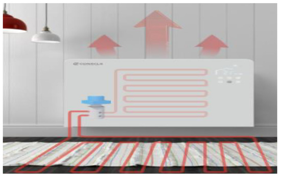
Figure 1.
Floor radiation-convection combined heating system.

Table 1.
System operation modes.
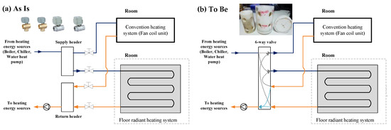
Figure 2.
Six-way valve.
Modes 1 and 2, shown in Table 1 are basic modes that operate by convection and radiation, respectively. In the different modes, the hot water flows to the convector or floor radiation panel, respectively. Mode 3 is an operation mode for units where intermittent heating is performed, such as in single-person residences. In Mode 3, hot water passes through the convector and flows into the floor radiation panel. Mode 4 is opposite to Mode 3, hot water flows into the floor radiation panel first and then into the convector. Figure 3 shows an operation mode suitable for occupants with a western lifestyle (left part of Figure 3), which mainly uses convection heating to quickly raise indoor temperature. Modes 1 and 3 correspond to this case. Figure 3 also depicts the Korean traditional lifestyle, in which floor heating is mainly used (right part of Figure 3), and convection heating is used as an aid. This method raises the temperature of the lower space in the room. Modes 2 and 4 are designed for this living style.
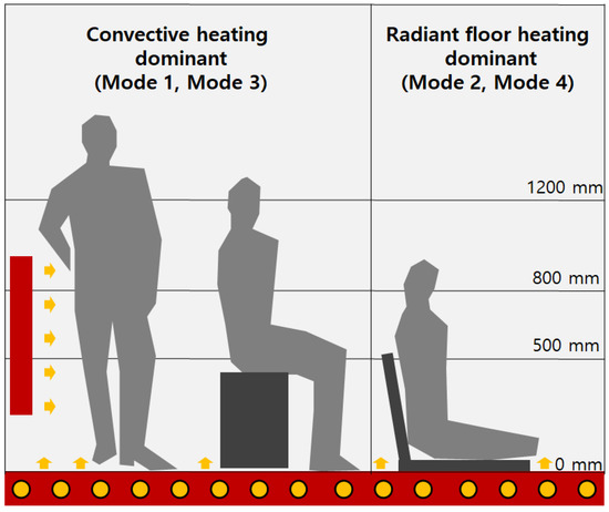
Figure 3.
System operating modes.
2.3. Indoor Thermal Comfort Indicator
In this study, PMV was used as an indoor thermal comfort indicator. The advantage of PMV is that it can rationally evaluate an indoor thermal environment considering the environment’s elements and the condition of the occupants. The ASHRAE and ISO standards suggest using PMV and the predicted percentage of dissatisfied (PPD) respondents as comfort indicators in an indoor environment [17,18]. The PMV can be calculated using Equations (1)–(5).
In this study, the metabolism of humans was set at 1.1 MET, and indoor clothing was set to 1.0 clo. The PMV and PPD are calculated using the air temperature taken at different heights. However, the other environmental factors were measured based on 1200 mm.
where, M is the metabolic rate (W/m2), W is the effective mechanical power (W/m2), Icl is the clothing insulation (m2∙K/W), fcl is the clothing surface area factor, ta is the air temperature (°C), tr is the mean radiant temperature (°C), var is the relative air velocity (m/s), pa is the water vapor partial pressure (Pa), hc is the convective heat transfer coefficient (W/m2∙K), and tcl is the clothing surface temperature (°C).
2.4. Test Chamber Setting
To evaluate the thermal comfort and energy consumption according to the target heating system, a radiant floor heating system and a convector were installed in a test chamber (Figure 4).
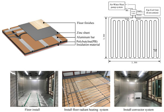
Figure 4.
Test chamber specifications.
To construct the radiant heating system in the floor, 12 mm polybutylene pipes were applied to the top of an insulation material. Aluminum bars and zinc sheets were applied to the top of the radiant heating system to facilitate heat transfer to the room. The convector uses hot water and has a heat dissipation of 2.3 kW. The electricity consumption of the convector is 20 W.
An electric heat pump was used as the heat source for the heating system, and the energy consumption of each system was measured using a power meter. Water was used as the medium for supplying heat to the heating system. The initial temperature of the heat medium (hot water) was set to 55 °C. Table 2 lists the main components of the heating system. The actual energy consumption of the heat pump to achieve the set indoor air temperature (28 °C) in the maximum operation load mode was measured.
Table 2.
Heating system specifications.
The heat cycle of the heat pump supplied the systems with hot water measuring 55 ± 1 °C. Hot water, maintained at a constant temperature, was supplied to each system at the same flow rate. The heat cycle of the heat pump stopped when the supply-return water difference was less than 3 °C.
Table 3 shows the specifications for the data logger with a T-Type thermocouple, the PMV, and the devices for measuring energy consumption. Figure 5 illustrates that the measurement was conducted in a test cell, 3300 mm (D) × 3300 mm (L) × 3300 mm (H) in size. The U-value of the wall was 0.15 W/m2·K (urethane panel 100 mm). The U-value of the window was 1.9 W/m2·K. The initial condition of the test chamber was 10 ± 0.3 °C air temperature and 50 ± 5% relative humidity. The temperature sensor was installed on the floor heating surface at three different points in even intervals around the system. Additionally, to measure the temperature conditions of each part of a room, the floor surface temperature and the air temperature of each level from the floor surface (50, 80, and 120 cm) were measured together. These measurements were used to analyze the indoor temperature conditions corresponding to the body position of the occupants.
Table 3.
Measuring instruments and measurement ranges.
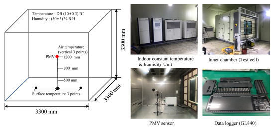
Figure 5.
Experimental set-up: test cell with the environment facility and measurement points and equipment.
3. Results
3.1. Indoor Temperature
Figure 6 shows the changes in surface temperature of the test chamber after heating commenced. Mode 1, which used only convection, showed the lowest floor temperature and thus it is inappropriate for occupants who sleep on the floor. By contrast, Modes 2, 3, and 4 showed high floor surface temperatures as hot water is supplied to the radiant floor heating panel. Mode 4 showed a higher temperature than Mode 2. Modes 2 and 4 supply hot water to the floor first. This means that these two modes can supply heat quickly to occupants who sleep on the floor or occupants who lead sedentary lifestyles.
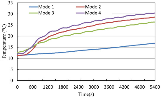
Figure 6.
Floor surface temperature.
Figure 7 illustrates the increase in the floor surface temperature. Notably, the floor temperature of Mode 4, which applies radiant floor heating and convection heating simultaneously, was higher than that of Mode 2, which only applies radiant floor heating. In Mode 4, the hot water that passes through the floor is used for convection heating. In other words, the radiant floor heating’s waste heat is used to raise the indoor air temperature, and it is presumed that this reduces the quantity of heat lost to indoor air from the floor surface.
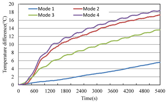
Figure 7.
Floor surface temperature increase.
Figure 8 shows the air temperature at 50 cm above the floor. Mode 4 showed the highest air temperature, whereas Mode 2 showed the lowest air temperature. The air temperature at 50 cm above the floor was higher in Modes 3 and 4 than in Modes 1 and 2.
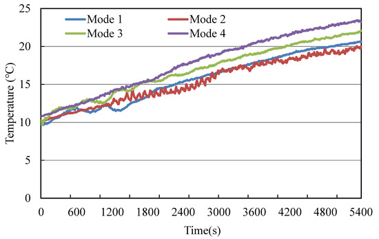
Figure 8.
Air temperature (50 cm from floor surface).
Figure 9 shows the air temperature at 80 cm above the floor, and Figure 10 shows the air temperature at 120 cm above the floor. The air temperature at 80 cm above the floor was the highest in Mode 1, followed by Mode 4 and Mode 3. Mode 2 showed the lowest air temperature. Thus, the indoor thermal temperature may be improved rapidly by applying convection heating, which is beneficial for occupants who adopt a standing-dominant lifestyle.
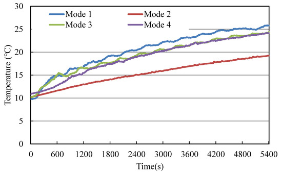
Figure 9.
Air temperature (80 cm from floor surface).
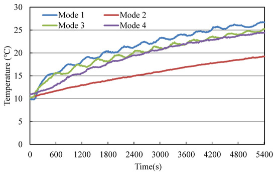
Figure 10.
Air temperature (120 cm from floor surface).
Table 4 shows the indoor temperature distribution after 90 min. The air temperature after 90 min was highest for Mode 1 at a height of 120 cm at 26.7 °C. The aggregated average temperature of Modes 2 and 3 were the same at 23.9 °C. The average air temperature of Mode 2 at 120 cm was the lowest at 19.5 °C. Mode 2 showed a lower air temperature than Mode 1 at 50 cm, 80 cm, and 120 cm, but the floor temperature was highest at 28.5 °C. Mode 3 reuses the waste heat of returned water from a convector to the heat floor panel, and the floor surface temperature of Mode 3 increased to 26.3 °C. This temperature was higher than the surface temperature of Mode 1, 16.8 °C. It is thought that Mode 3 provides occupants with a better thermal sensation than Mode 1 during the heating season. Mode 4 also uses the waste heat from the radiant floor heating panel to heat the indoor air by the convector, which is contrary to Mode 2, sending returned hot water to the air-water heat pump system. Additional heat influx to the indoor air by the convector in Mode 4 increased the indoor air temperature, in contrast to Mode 2. It is interesting that the floor surface temperature of Mode 4 is higher than that of Mode 2. It is thought that the heat loss from the radiant floor panel to the indoor air is reduced due to the increased indoor temperature in Mode 4. Consequently, the drop in temperature at the surface of the radiant floor panel has to be reduced in Mode 4.
Table 4.
Indoor temperature pattern after heating for 90 min.
The temperature difference between the highest and lowest height was greatest in Mode 1; thus, the convection heating mode was the least comfortable. By contrast, Mode 2 showed a maximum–minimum temperature difference of 0.8 °C; thus, it had the highest comfort. Modes 3 and 4 showed maximum–minimum temperature differences of 3.2 °C and 1.2 °C, respectively.
Based on these indoor temperature distribution results, Mode 4 can increase the indoor air temperature to a relatively high level while maintaining a small temperature difference between the highest and lowest height.
3.2. Predicted Mean Vote (PMV)
Figure 11 shows the PMV measurements after 90 min. Figure 11a shows the result for the PMV and PPD variations in Mode 1. A comparison of these three PMV variation curves shows that the PMV were higher at 80 cm and at 120 cm than at 50 cm, and at 80 cm and at 120 cm the PPD was dramatically decreased to the range recommended by ISO 7730 with PPD < 10%.
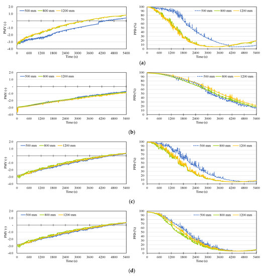
Figure 11.
Evaluated PMV and PPD values. (a) Mode 1 results for PMV and PPD; (b) Mode 2 results for PMV and PPD; (c) Mode 3 results for PMV and PPD; (d) Mode 4 results for PMV and PPD.
In the mode using the convector system, the PPD results for 80 cm and at 120 cm decreased earlier than at 50 cm because the supplied warm air of the convector system influenced the air temperature in the space between 80 cm and 120 cm.
Figure 12 shows the time slot of each mode in which the PMV is in the comfort area. When the PMV value is in the range of −0.5 to +0.5, the human body feels thermally comfortable. The indoor thermal environment entered the comfort area earliest in Mode 12,050 s after heating began; however, the room became overheated and exceeded the comfort range at 4030 s. This is because the results for the same operation time were used to understand the characteristics of each mode. In Modes 3 and 4, the indoor thermal environment entered the comfort area after 3230 s and 3310 s, respectively, and it was maintained until 5400 s. In the case of radiant floor heating, the indoor PMV value stayed below the comfort area until after 90 min.
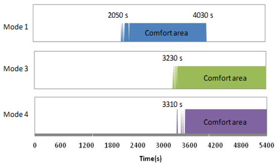
Figure 12.
Time period of each mode corresponding to the comfort area.
Overall, the results imply that the convection heating system can quickly provide “warm” thermal comfort (PMV −0.5(–) OVER) at a height of 1.2 m. Mode 3 and Mode 4 had a similar impact on the indoor temperature and comfort at a height of 1.2 m.
3.3. Electricity Consumption
Figure 13 shows the electricity consumption of each operating mode. Table 5 shows the energy consumption of each operation mode during the 90 min study period.
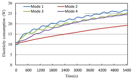
Figure 13.
Electricity consumption of each operating mode.
Table 5.
Energy consumption after 90 min.
These results showed the total energy used for space heating for each mode. Mode 2 showed the lowest energy consumption whereas Mode 1 showed the highest energy consumption. Table 6 shows the electric energy expended to raise the indoor air temperature by 1 °C up until 90 min when the heating system’s operation was complete. Mode 2 consumed the most energy in order to raise the indoor air temperature by 1 °C. Modes 1, 3, and 4 showed similar energy consumption rates.
Table 6.
Energy use effectiveness.
4. Discussion
Overall, the results were consistent with the characteristics of the general convection heating system and radiant heating system. The most notable operation modes were Modes 3 and 4. These two modes correspond to the simultaneous operation of floor radiation and convection heating systems.
Mode 4 showed superior performance in several aspects compared to the other systems. With regard to the temperature distribution of Mode 4, the temperature in the lowest area (50 cm above the floor) was the highest, and the temperature in the highest area was also high, which was similar to conditions in the convection heating operation. Furthermore, the average air temperature after 90 min in Mode 4 was also the highest, while the temperature difference between the highest and lowest heights was small, which was similar to the radiant floor heating system. The indoor average temperature in Mode 2 was 19.5 °C, which was much lower than the 23.9 °C average of Mode 4. The basic operating conditions of Mode 4, where hot water flows into the floor radiation panel first, are the same as that of Mode 2. However, Mode 4 has an advantage in that the returned hot water is used by the convector, thereby increasing the total quantity of heat supplied to the room. Modes 3 and 4 showed similar characteristics in terms of using waste heat. However, Mode 4 was more effective in radiant heating. Hence, Mode 4 is able to maintain a lower temperature difference between the upper and lower heights and it can maintain a high floor surface temperature after 90 min.
The PMV measurement results indicate that radiant floor heating is not appropriate for intermittent heating. In other words, residents of single residences who return home at night will be in discomfort for a long time if they use floor heating. In this case, Mode 1, which is convection heating, and Modes 3 and 4, which represent mixed modes are more comfortable. Based on the above results, Mode 4 is considered to be an appropriate hybrid operation mode that is applicable to occupants with both active and sedentary lifestyles. The existing literature suggests that radiant floor heating is generally efficient for occupants with a sedentary living style. However, the results of this study suggest that Mode 4 is superior to the existing radiant heating system because it can increase the indoor air temperature more rapidly.
Mode 4 uses the waste heat from the returned warm water from a radiant floor heating system to heat the indoor air. This action increases both the indoor and surface temperature of the radiant panel. This result suggests that, in terms of heating, Mode 4 is energy efficient, and at the same time, it keeps the indoor space warmer than the other operating modes.
5. Conclusions
In this paper, the thermal performance of a novel combined radiant-convection floor heating system was evaluated by comparing four different modes, convection only, floor radiation only, convection (dominant)+floor radiation (sub), and floor radiation (dominant)+convection (sub) while considering the occupants’ lifestyle.
The PMV and PPD results indicate that radiant floor heating is not appropriate for intermittent heating. In other words, residents of single residences who return home at night will feel discomfort for a long time if they heat their room using floor heating. In this case, Mode 1, which is convection heating, and Modes 4, which represents a mixed mode are more comfortable. The results showed that Mode 4, which recovers waste heat by sending it to the convector from the hot water returned from the floor radiation panel, is the most efficient operation mode in terms of comfort and energy consumption. The main reason for this is the operation method of Mode 4, which combines waste heat using a convector with radiant floor heating. The key results are as follows.
(1) Mode 1, which used only convection, showed the lowest floor surface temperature (16.8 °C) and thus it is inappropriate for occupants who sleep on the floor. In contrast, Modes 2, 3, and 4 showed high floor surface temperatures as hot water is supplied to the radiant floor heating panel. After heating for 90 min, Mode 4 showed that the air temperature at 50 cm, at 80 cm, and at 120 cm increased uniformly. The highest floor surface temperature was 30.5 °C.
(2) The PMV results showed that Mode 1 entered the comfort area for the indoor thermal environment first; however, it quickly exceeded the comfort range because it heated up the environment too rapidly. The PPD was also dramatically decreased to the range recommended in ISO 7730 with PPD < 10%. Modes 3 and 4 satisfied the indoor thermal comfort range more slowly than Mode 1. Mode 2, which corresponds to radiant floor heating, showed the slowest heating rate as the indoor thermal environment did not enter the comfort area until 90 min after heating began due to the time-lag effect of radiation.
(3) With regard to energy consumption, the total energy used for space heating, that is, to raise the indoor temperature by 1 °C was 134.7 Wh/△T for Mode 4. This value is similar to the value for Mode 1 (134.4 Wh/△T). Mode 2 showed the lowest energy consumption rate after 90 min (150.2 Wh/△T); it also had the lowest indoor air temperature.
The results of this study are limited in that the laboratory conditions did not consider room ventilation and aspiration. In the future, the performance of each operation mode should reflect the actual conditions of infiltration, ventilation, etc.
Author Contributions
B.P. designed the experimental study and performed the chamber test. C.H.C. contributed to the analysis and writing of the manuscript. S.R.R. contributed to the review papers and method writing of the manuscript. All authors have read and agreed to the published version of the manuscript.
Funding
This research received no external funding.
Conflicts of Interest
The authors declare no conflict of interest.
References
- Yeo, M.S.; Yang, I.H.; Kim, K.W. Historical changes and recent energy saving potential of residential heating in Korea. Energy Build. 2003, 35, 715–727. [Google Scholar] [CrossRef]
- Bean, R.; Kim, K.W. Part 1: History of radiant heating & cooling systems. ASHRAE J. 2010, 52, 40. [Google Scholar]
- Olesen, B.W. Radiant floor heating in theory and practice. ASHRAE J. 2002, 44, 19. [Google Scholar]
- Lin, K.; Zhang, Y.; Di, H.; Yang, R. Study of an electrical heating system with ductless air supply and shape-stabilized PCM for thermal storage. Energy Convers. Mgmt. 2007, 48, 2016–2024. [Google Scholar] [CrossRef]
- Baek, S.; Park, J. Proposal of a PCM underfloor heating system using a web construction method. Int. J. Polym. Sci. 2017, 2017, 2693526. [Google Scholar] [CrossRef]
- Kong, S.H.; Sohn, J.Y. Thermal comfort criteria for Korean people in Ondol heating system. J. Archit. Inst. Korea 1998, 4, 167–174. [Google Scholar]
- Woo, B.-K.; Lee, S.; Kim, S.U. Research on the actual condition of under floor radiant heating for apartment housing. KIEAE J. 2007, 7, 81–86. [Google Scholar]
- Cho, J.; Park, B.; Lim, T. Experimental and numerical study on the application of low-temperature radiant floor heating system with capillary tube: Thermal performance analysis. App. Therm. Eng. 2019, 163, 1–14. [Google Scholar] [CrossRef]
- Sarbu, I.; Sebarchievici, C. Performance evaluation of radiator and radiant floor heating systems for an office room connected to a ground-coupled heat pump. Energies 2016, 9, 228. [Google Scholar] [CrossRef]
- Benakopoulos, T.; Salenbien, R.; Vanhoudt, D.; Svendsen, S. Improved control of radiator heating systems with thermostatic radiator valves without pre-setting function. Energies 2019, 12, 3215. [Google Scholar] [CrossRef]
- Shin, M.S.; Rhee, K.N.; Ryu, S.R.; Yeo, M.S.; Kim, K.W. Design of radiant floor heating panel in view of floor surface temperatures. Build. Environ. 2015, 92, 559–577. [Google Scholar] [CrossRef]
- Bojić, M.; Cvetković, D.; Marjanović, V.; Blagojević, M.; Djordjević, Z. Performances of low temperature radiant heating systems. Ener. Bldgs. 2013, 61, 233–238. [Google Scholar] [CrossRef]
- Strand, K.; Pederson, O. Modeling radiant systems in an integrated heat balance based energy simulation program. ASHRAE Trans. 2002, 108, 1–9. [Google Scholar]
- Miriel, J.; Serres, L.; Trombe, A. Radiant ceiling panel heating–cooling systems: Experimental and simulated study of the performances, thermal comfort and energy consumptions. App. Ther. Eng. 2002, 22, 1861–1873. [Google Scholar] [CrossRef]
- Rahimi, M.; Sabernaeemi, A. Experimental study of radiation and free convection in an enclosure with under-floor heating system. Energy Convers. Mgmt. 2011, 52, 2752–2757. [Google Scholar] [CrossRef]
- Safizadeh, M.R.; Schweiker, M.; Wagner, A. Experimental evaluation of radiant heating ceiling systems based on thermal comfort criteria. Energies 2018, 11, 2932. [Google Scholar] [CrossRef]
- ANSI/ASHRAE Standard 55-2013, Thermal Environmental Conditions for Human Occupancy. Available online: https://www.amazon.com/Standard-Environmental-Conditions-Occupancy-Approved/dp/B00Q63TV2S (accessed on 2 February 2020).
- ISO 7730:2010 Ergonomics of the Thermal Environment—Analytical Determination and Interpretation of Thermal Comfort Using Calculation of the PMV and PPD Indices and Local Thermal Comfort Criteria. Available online: https://infostore.saiglobal.com/en-us/standards/ks-a-iso-7730-2010-649288_SAIG_KSA_KSA_1488312/ (accessed on 2 February 2020).


© 2020 by the authors. Licensee MDPI, Basel, Switzerland. This article is an open access article distributed under the terms and conditions of the Creative Commons Attribution (CC BY) license (http://creativecommons.org/licenses/by/4.0/).