Abstract
In this paper, an improved sensorless vector control method for an interior permanent magnet synchronous motor (IPMSM) drive with small DC-link capacitors is proposed. First, a fast sliding-mode observer was applied, to enlarge the observer bandwidth. Then, an improved estimator based on a proportional integral resonant controller was designed for the estimate speed shaping, which means the actual speed can be tracked. This not only reduces the position estimate error, but also enhances the grid power factor and suppresses the input current harmonics. Simulation and experiments were conducted on a sensorless IPMSM drive system with a small film capacitor. The effectiveness of the proposed estimation method was verified by the simulation and experimental results. The estimated error was reduced and the grid current harmonics satisfy the requirements of EN61000-3-2.
1. Introduction
At present, interior permanent magnet synchronous motors (IPMSMs) are widely used in industrial and white home applications due to their superior efficiency, power density, and torque-to-inertia ratio [1,2,3]. The accurate rotor position and speed are the necessary information for control of the motor. Nevertheless, the position sensors are very expensive and fragile [4]. In order to remove the shaft position sensors, the position and speed sensorless control method must be used. The sensorless control methods can be classified into two classes [5,6]. The first class are high frequency (HF) injections suited to low and zero speed operations [7,8]. The other class is based on the back electromotive force (EMF) machine model for mid- and high-speed operations [9,10]. Recently, as the sliding-mode observer (SMO) method has been seen to have the attractive advantages of robustness to disturbances, good dynamic performance, and low sensitivity to parameter variations [11], it is widely used in many devices, such as fans, pumps, and air compressors.
Generally, in traditional AC-DC-AC IPMSM drive systems, large capacity electrolytic capacitors are utilized at the DC-link to obtain a stable DC-link voltage. The electrolytic capacitor has a large volume [12,13,14,15]; about 20% to 40% of high power drives’ volume would be occupied. In addition, the electrolyte may evaporate, thus it decreases the reliability of drive system [16,17,18,19]. As film capacitors have much longer lifetimes and less capacitance per unit, many studies have focused on replacing electrolytic capacitors with film capacitors [20,21,22,23].
However, in small capacitor drive systems, the DC-link voltage fluctuates with twice the grid frequency. Thus the motor torque and speed also varies periodically, which may lead to difficulties in sensorless operations [24,25,26], which are limited by the SMO bandwidth. In addition, error and distortions of the estimated speed would generate harmonics on the grid side. Increasing the observer gain can improve these issues, but high gains would produce chattering in the estimation. So, a sensorless control method should be designed to meet the needs of a small dc-link capacitor drive system.
Much research effort has gone into the development of sensorless drives. In [27,28], online parameters identifications were used to improve the estimate robustness. In [29,30,31], nonlinearity compensations were applied to reduce the estimated error. Adaptive filters were designed to filter out the undesired harmonic components in back EMF by analyzing the harmonic distribution of position estimated error, such as adaptive notch filter (ANF) [11], synchronous frequency extract filters (SFFs) [32], adaptive linear neural (ADALINE) filter [33], adaptive vector filter (AVF) [34], and so on. All of these techniques can improve the sensorless control quality, but have little impact on dynamic performance.
Hence, compared with large capacity electrolytic capacitors, the dynamic performance and response of the sensorless control must be improved. In [35,36,37], the SMO is implemented in field-programmable gate array (FPGA) to improve control bandwidth and system robustness. In [24] and [38], sample and pulse width modulation methods have been proposed, the DC-link bus voltage is sampled several times in the carrier half-period. The accuracy of the stator voltage is improved during sensorless control. To increase the sampling times, an iterative sliding mode observer (ISMO) was proposed in [39]; the SMO iteratively executed four times in one current control cycle, and the phase delay and the ripples in the estimation of the back EMF were minimized. An estimator based on third-harmonic back electromotive force is presented to improve the dynamic performance [40]. Although the bandwidth of SMO was enlarged by these methods, the previous studies for the sensorless control were mainly aimed at the electrolytic capacitor system.
Considering the contradiction between the SMO bandwidth limitation and motor speed fluctuation caused by a small DC-link capacitor, this paper focuses on the dynamic performance of speed estimation for IPMSM drive system. A conventional SMO that is executed five times per current control cycle and called the fast sliding-mode observer (FSMO) is proposed. It is much faster than that in [24] and [38,39]. The ripples in the estimation of the back EMF can be minimized. Therefore, the estimation error is diminished and the bandwidth is extended. Moreover, as the speed contains a sinusoidal alternating component of high frequency, the estimated speed delay and distortion would generate harmonics during power control operations. Thus, an improved estimator was adopted to shape the estimated speed. With the proportional-integrational-resonant (PIR) controller in software quadrature phase-locked loop (PLL), the estimated speed can track the actual speed better and the dynamic performance could be enhanced. Based on the FSMO and the PIR controller, the improved sensorless vector control method has a fast response. It is suitable for use with a drive system with a small DC-link capacitor which requires high power factor and low input current harmonics.
This paper is organized as follows. In Section 2, the characteristics of motor speed and torque in a small DC-link capacitor drive system are presented, and the causes of estimation error are analyzed. In Section 3, the proposed sensorless vector control method, including FSMO and an improved estimator based on the PIR controller are discussed and realized, including transfer function and stability analysis. Finally, the effectiveness of the proposed sensorless vector control method is verified with a 1.0-kW sensorless IPMSM drive.
2. Analysis of IPMSM Drive with Small DC-Link Capacitor
2.1. Torque and Speed Characteristics of Small DC-Link Drive System
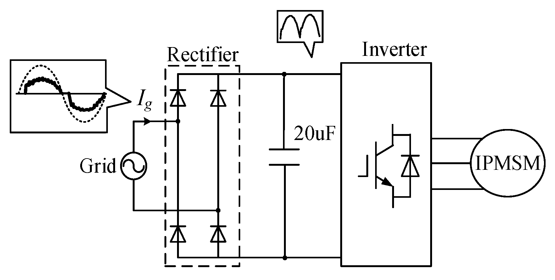
In order to remove the influence of the film capacitor on sensorless control, the characteristics of the drive system should be analyzed firstly. As shown in Figure 1, the system consists of a single-phase diode rectifier, a small film capacitor at the dc-link, and a three phase inverter.

Figure 1.
Circuit diagram of the inverter with small DC-link capacitor.
The grid voltage can be presented as follows [12,13]:
where Ug is grid input voltage amplitude, θg is the phase angle of the grid.
In order to obtain high power factors and reduce grid current harmonics, the grid input current must be synchronized with grid voltage. So the expected grid input current can be given as:
where Ig is the amplitude of the grid current. So the expected grid input power Pg can be calculated as
Compared to a traditional drive system, the small volume of the film capacitor cannot maintain the DC-link voltage constant. The DC-link voltage will fluctuate with twice the frequency of the grid voltage, and it can be expressed as:
As a result, the capacitor power Pc can be calculated as follows
where ωg is angular speed of the AC grid, Cdc is the capacitance of the DC-link capacitor. The inverter output power can be calculated as follows:
The electromagnetic torque can be calculated as follows [21,22]:
where ωr is the rotor mechanical speed, T0 is the DC component, Tx is the ac component, is the torque phase.
The mechanical motion equation of IPMSM is given as
where Te is the electromagnetic torque, TL is the load torque, B is the viscous coefficient, and J is the moment of inertia, respectively. The angle speed of IPMSM can be expressed as:
where ω0 is the DC component, ωx is the ac component, is the speed phase.
From Equation (9), in a small DC-link drive system, the speed and torque of the rotor is sinusoidal and varies periodically with twice the grid input voltage frequency.
2.2. Position Estimation Based on the SMO
The extended electromotive force model on the stator frame coordinate of IPMSM can be described as follows [4]:
where uα, uβ, iα and iβ are voltages and currents on α-β coordinate, respectively. R, Ld and Lq are the stator resistance and inductance, respectively. ωe is the rotor electrical speed, θe is the rotor electric angular, and p is the differential operator. Eext is the defined as the extended electromotive force. The stator current equation of IPMSM on α-β coordinate can be described as follows:
And the back electromotive force can be described as follows:
It can be seen that the back EMF signal contains the information of rotor speed and position. Therefore, after the back EMF signal is estimated by using the observer, the rotor speed and position information can be obtained.
Based on the sliding-mode variable structure theory, the sliding surface is selected as [9]:
where is the estimated current value, is the actual measure value. On the basis of Equations (11) and (12), the SMO can be expressed as:
where sgn() is the sliding mode control functions, which can be the sign, saturation or sigmoid functions of current errors. l is the sliding mode gain. To get the back EMF, the motor state observation model is setup, and are the estimated values that are calculated from the mathematical model. According to the principle of SMO, the actual value is used to modify the state estimate, which turn the estimated back EMF value approximates into the actual values. The back EMF can also be expressed as:
where m is the positive observer gain.
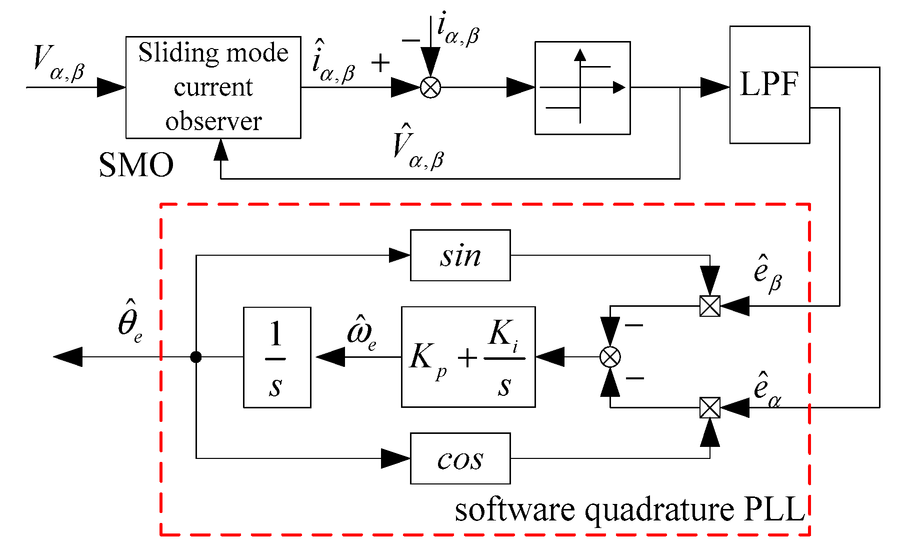
When the system state reaches the sliding mode, the current errors approach zero, and the eα and eβ can be used as the estimated back EMF. Then, the observed back EMFs are used to get the rotor position and speed by the software quadrature PLL. The block diagram of position and speed estimations using the SMO and PLL is shown in Figure 2.
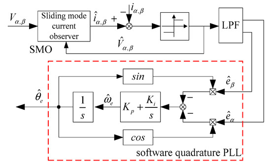
Figure 2.
Conventional position and speed estimate based on sliding-mode observer (SMO) and quadrature phase-locked loop (PLL).
The estimated rotor position obtained from the quadrature PLL can be expressed as follows:
2.3. Problems of SMO with Small DC-Link Capacitor
In conventional SMO, the sign switching function is a discontinuous control. This Bang-Bang control may generate a severe chattering in the back EMF [34]. To reduce the chattering, a low pass filter (LPF) should be used after the output of the sign function. However, this low-pass filter also causes a long time delay in estimating the position of the rotor, which degrades the estimation performance and precision, especially in high-power or high-speed IPMSM drive applications.
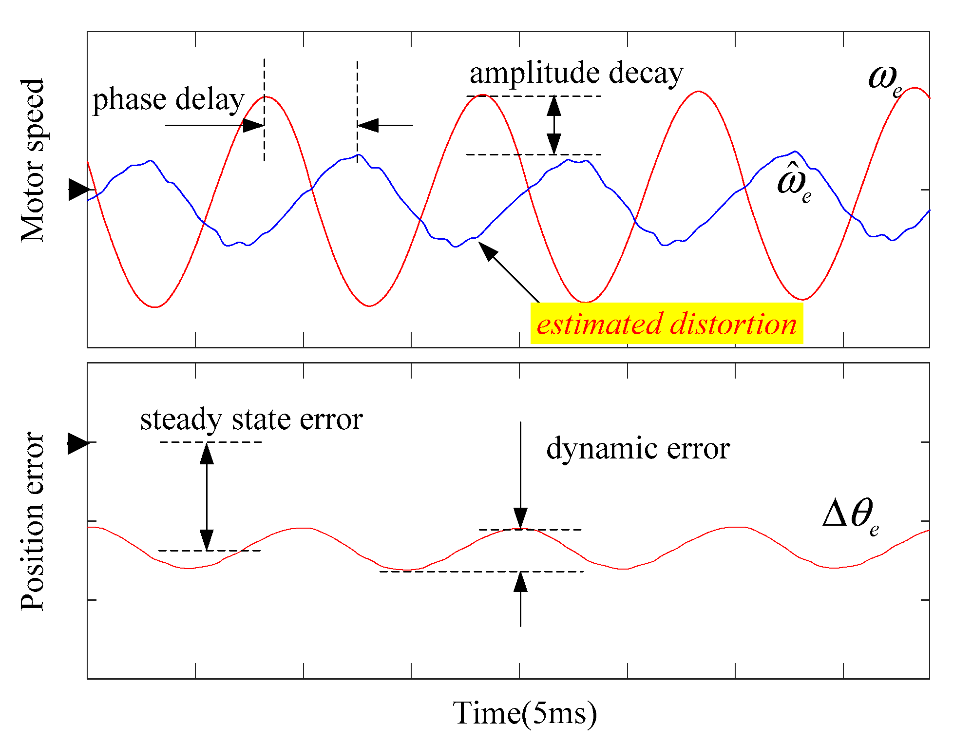
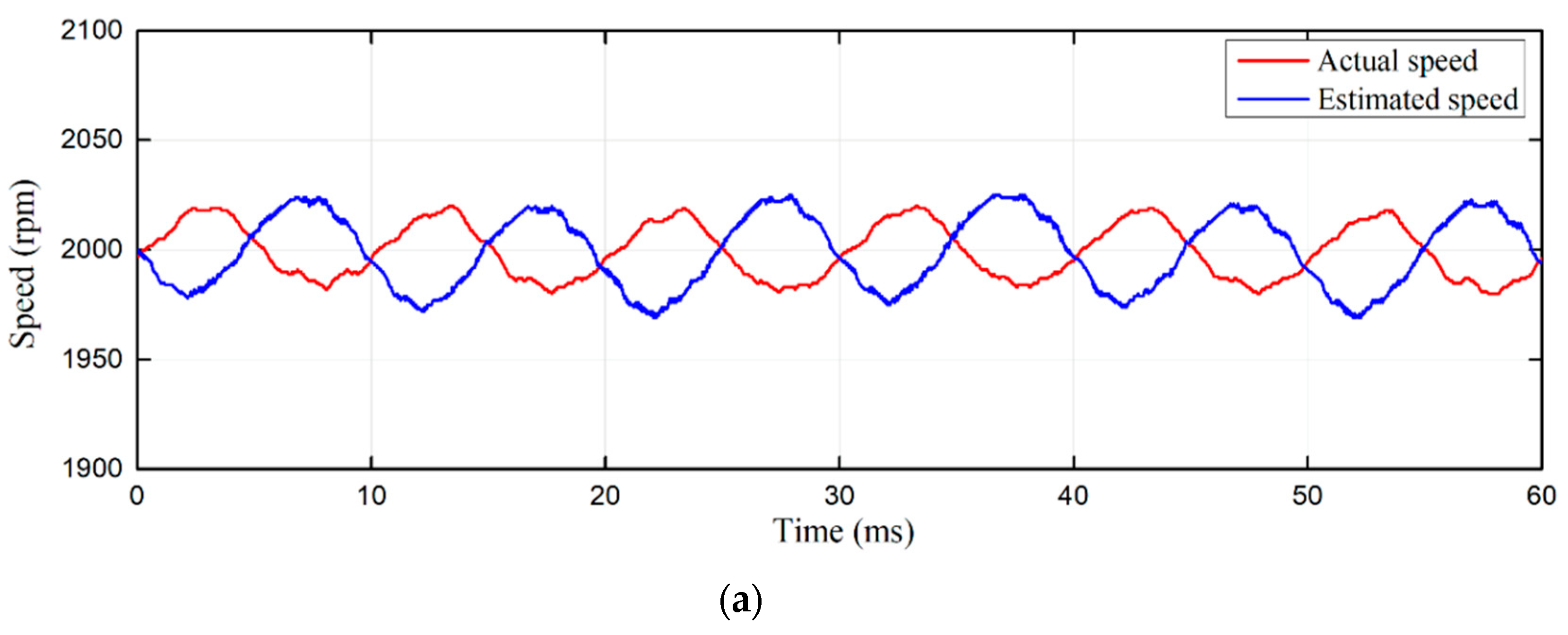
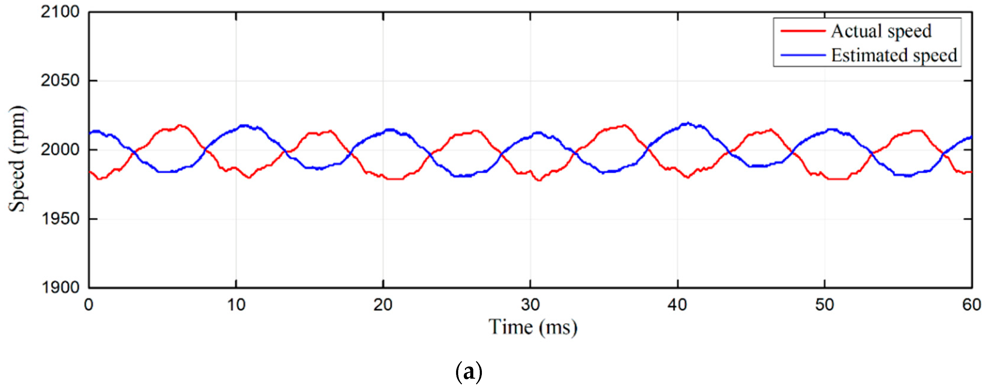
Besides, on the basis of Equations (7) and (9), the torque and speed of the motor consist of a DC component and an AC component which fluctuate with twice the input voltage frequency. As shown in Figure 3, the phase delay time is about 4 ms, while the estimated speed amplitude is only half of the real speed. The actual speed cannot be tracked well enough. The phase delay, amplitude decay, and waveform distortion of the estimated speed will generate harmonic components in the grid current, which is undesirable for a small DC-link capacitor drive system. Furthermore, the position estimate error also contains a steady-state error and a dynamic error, which leads the performance of the sensorless control to degrade. In order to solve these problems, the dynamic performance of the SMO should be improved to meet a wide range of frequencies.
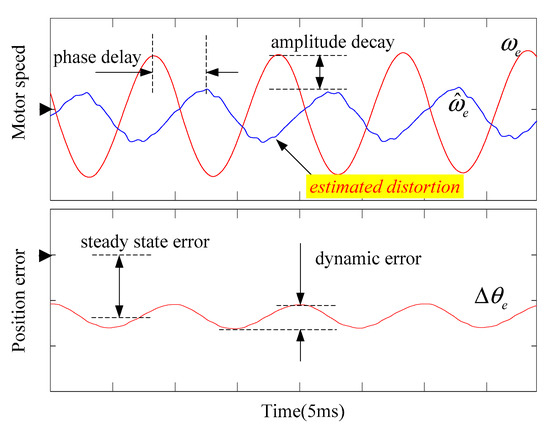
Figure 3.
Simulation results of the SMO with small DC-link capacitor.
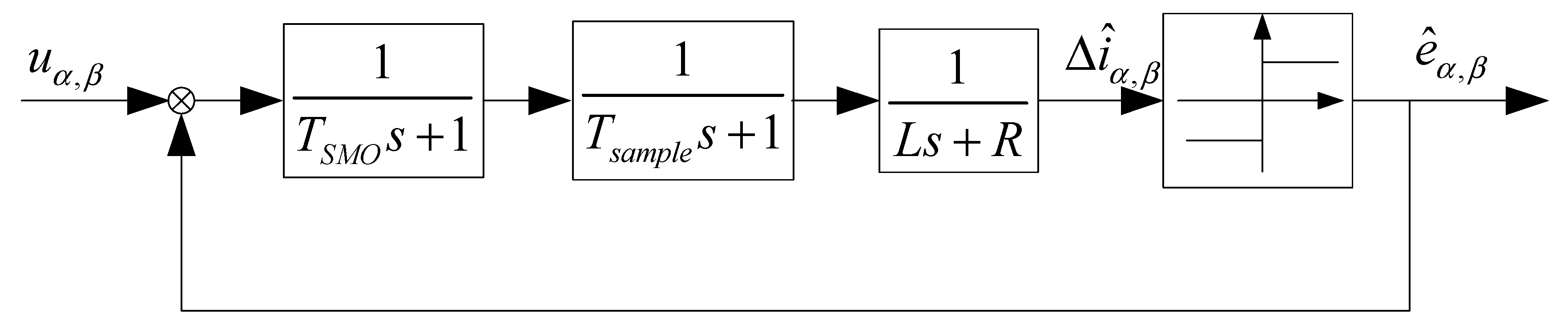
It is well known that the dynamic response of the estimation is restricted by the bandwidth of the SMO control loop. The equivalent block diagram of the SMO is shown in Figure 4. TSMO is the SMO control period. Tsample is voltage and current sample delay time. τ= L/R is the electromagnetic time constant of motor, with τ >> TSMO and Tsample, therefore the simplified open loop transfer function becomes:
where Td = TSMO + Tsample. In this second-order control system, the SMO control bandwidth is as follows [41]:
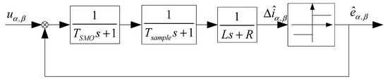
Figure 4.
Equivalent block diagram of the conventional SMO.
There are two major limiting factors for SMO bandwidth. The first factor is the SMO control cycle. The other factor is the digital delay time which includes sampling time, algorithm execution time, and so on.
3. The Proposed Sensorless Vector Control Method
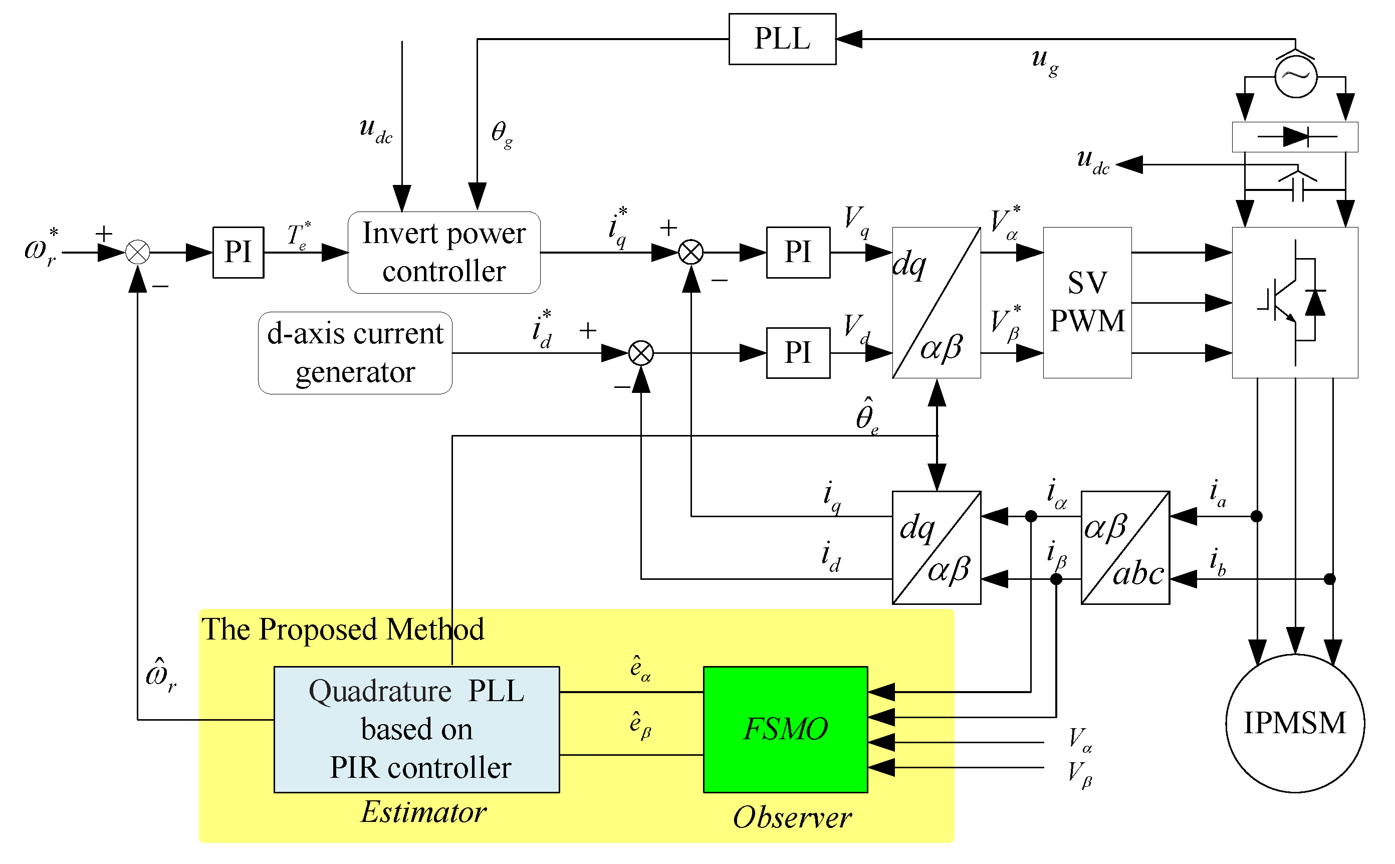
The sensorless vector control scheme of the IPMSM drive with a small DC-link capacitor is shown in Figure 5.

Figure 5.
Interior permanent magnet synchronous motor (IPMSM) sensorless control with small DC-link capacitor.
The inverter power controller is used to control the inverter power, which mainly generates the q-axis current reference [16]. The generation of the current reference for flux weakening should take the DC-link voltage fluctuation into consideration. The proposed SMO is applied to estimate the back EMFs with little phase shifts in the α-β reference frame. Then the position and speed of the rotor are obtained by the software PLL according to the observed back EMFs. The PIR controller is incorporated in the software quadrature PLL, which contains proportional, integrator and sinusoidal tracking controllers. With the proposed controller, the sinusoidal actual speed can be tracked better and the estimated position error can be reduced.
3.1. FSMO
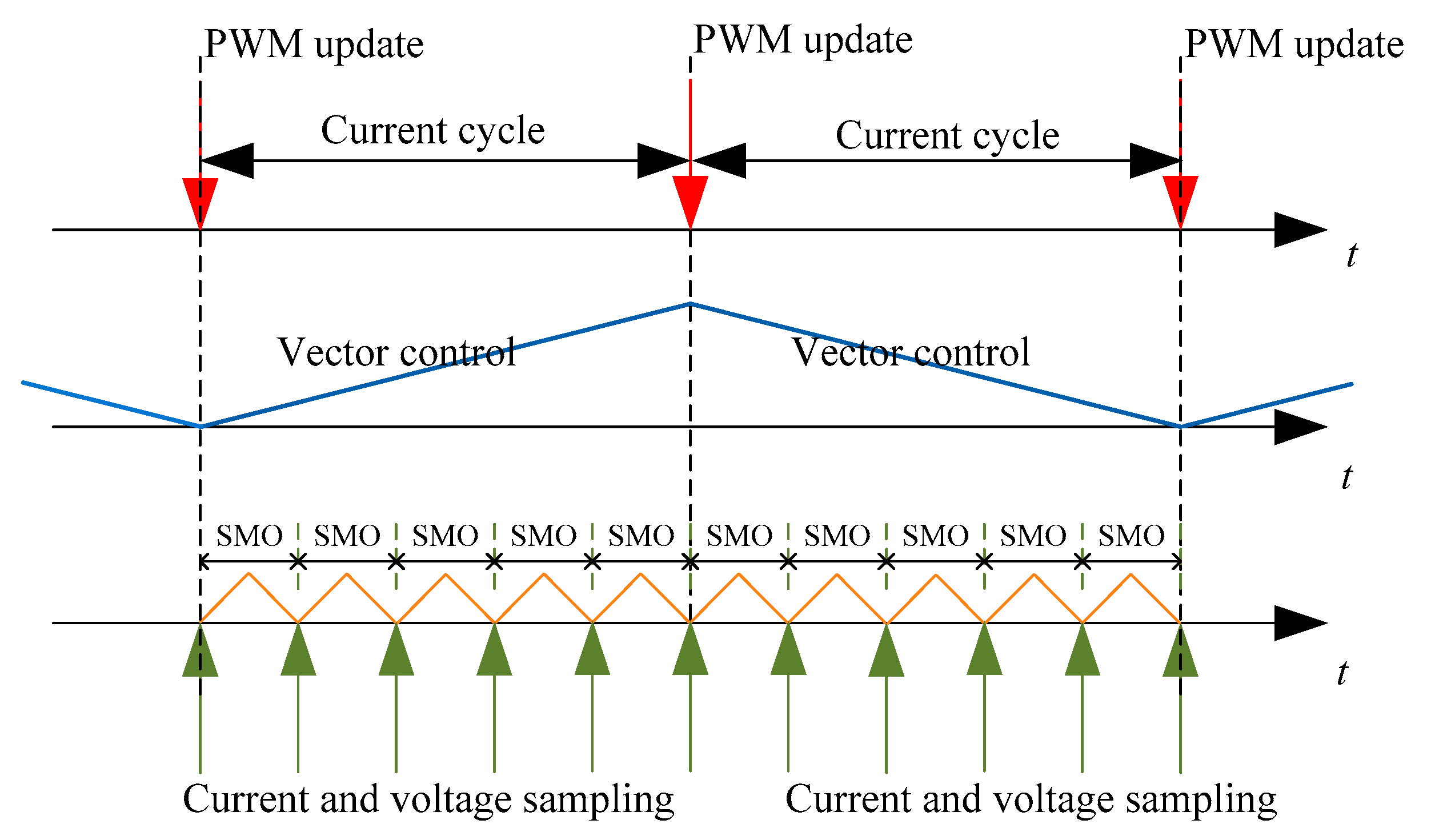
In this part, an FSMO method to remove the chattering in back EMF and reduce the estimate error is described. As shown in Figure 6, it is composed of the pulse-width modulation (PWM) update and SMO samplers. The PWM update can be executed at peak or valley of triangular carrier, which is doubled compared to the PWM frequency. The bandwidth of current control is enlarged [38], which is beneficial in terms of good power control quality in small DC-link capacitance drives [12], and the current ripples would be minimized. Ignoring the high-frequency switching harmonics, uα, uβ, iα and iβ in the observer calculating process of the SMO becomes smoother.
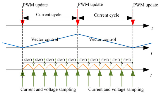
Figure 6.
Typical sequential of PWM update and SMO sampling.
Furthermore, in the SMO samplers, the SMO and the software quadrature PLL of the estimator are executed five times per current control cycle. The stator currents and the DC-link voltage are sampled at the beginning of SMO. Thus the voltage and current changes in one current cycle can be detected in real time to improve the accuracy of the stator voltage and current in the SMO. The sign function and low pass filter are replaced with sigmoid function to suppress chattering in the back EMF [10,39]. With the sampling delay time and control period reduction, the FSMO can extend the observer bandwidth effectively [33]. Therefore, the estimate error can be reduced, and the system would get a rapid response and good dynamic performance for sensorless control.
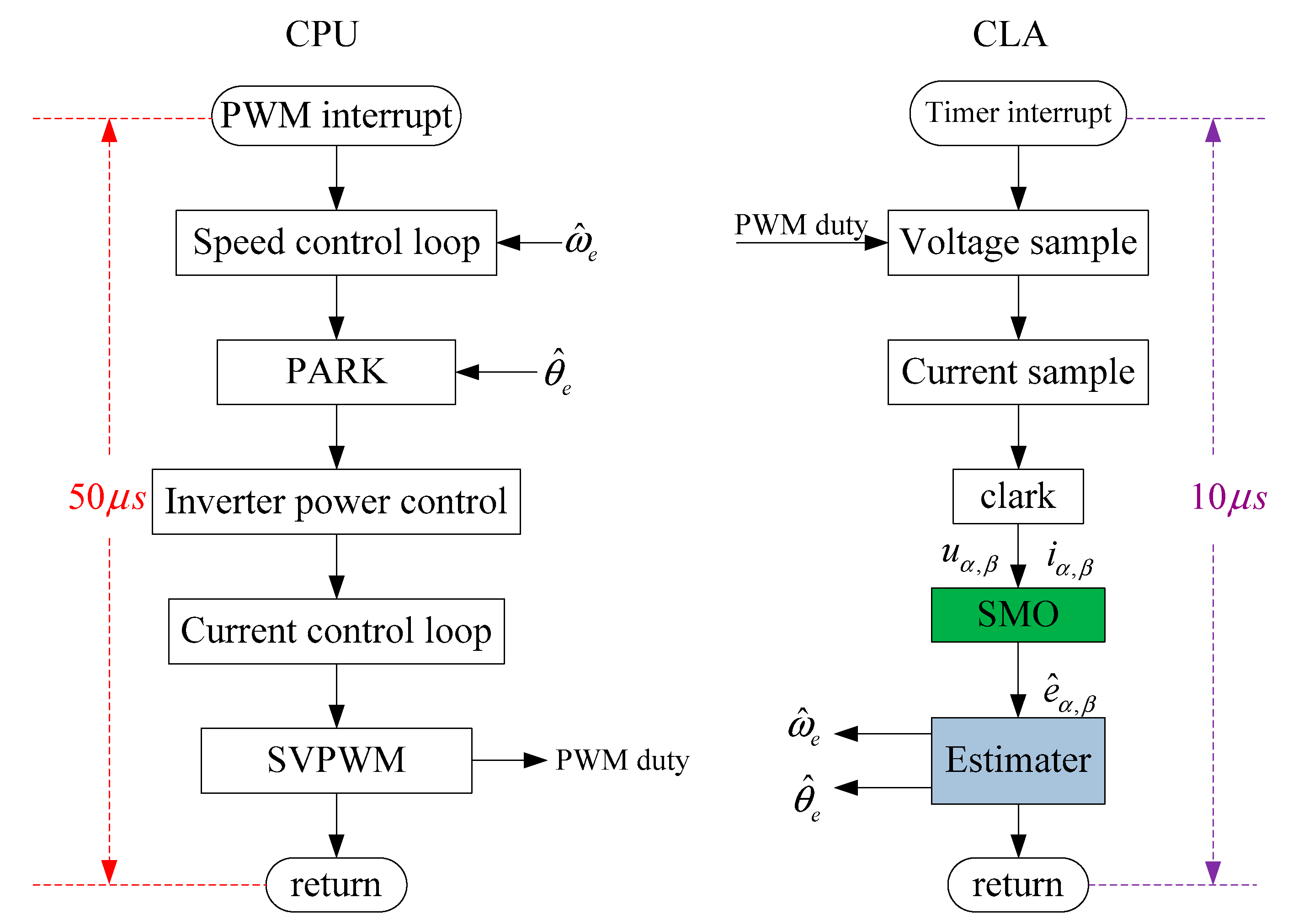
On the basis of the above analysis, since the number of samples is limited by the CPU’s processing speed, a digital signal processor (DSP), which consists of a CPU and a control law accelerator (CLA), was adopted to execute the whole control algorithm. As shown in Figure 7, the CPU was mainly used to perform vector control and power control. The CLA only performs SMO, ensuring the SMO can be implemented more times in one current control cycle. All of these control algorithms were executed on a DSP chip without any additional cost.
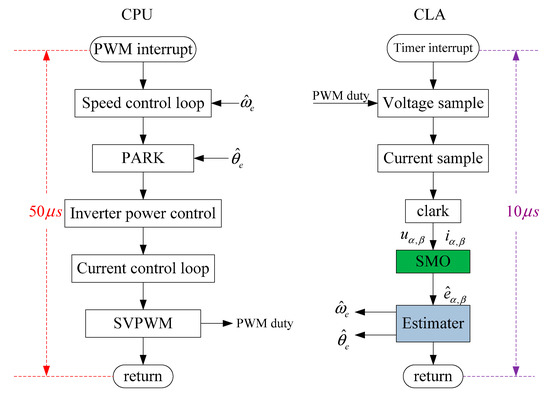
Figure 7.
Block diagram of the implemented digital signal processor (DSP) algorithm.
3.2. Improved Position Estimator Based on PIR Controller
In general, the estimated rotor position and speed can be calculated directly from back EMF information, and the general rotor position estimators can be divided into two types. One type is the anti-tangent function [10], but it is more sensitive to noise and harmonics in back EMF eα and eβ. For example, when the eα is close to zero, an obvious estimation error may occur using arc-tangent calculation, due to the noise. The other is software quadrature PLL [33]. The estimated speed can be expressed as:
where Kp is the proportional gain, and Ki is the integral gain. The estimated speed performance depends on the bandwidth of the proportional integral (PI) regulator in quadrature PLL. Based on speed analysis of the drive system, the speed contains a sinusoidal component which fluctuates with twice the grid frequency. The bandwidth of a traditional PI controller is lower [33]; the estimated speed will be greatly delayed and a steady-state error will occur. Thus, it is necessary to design a suitable controller in the quadrature PLL.
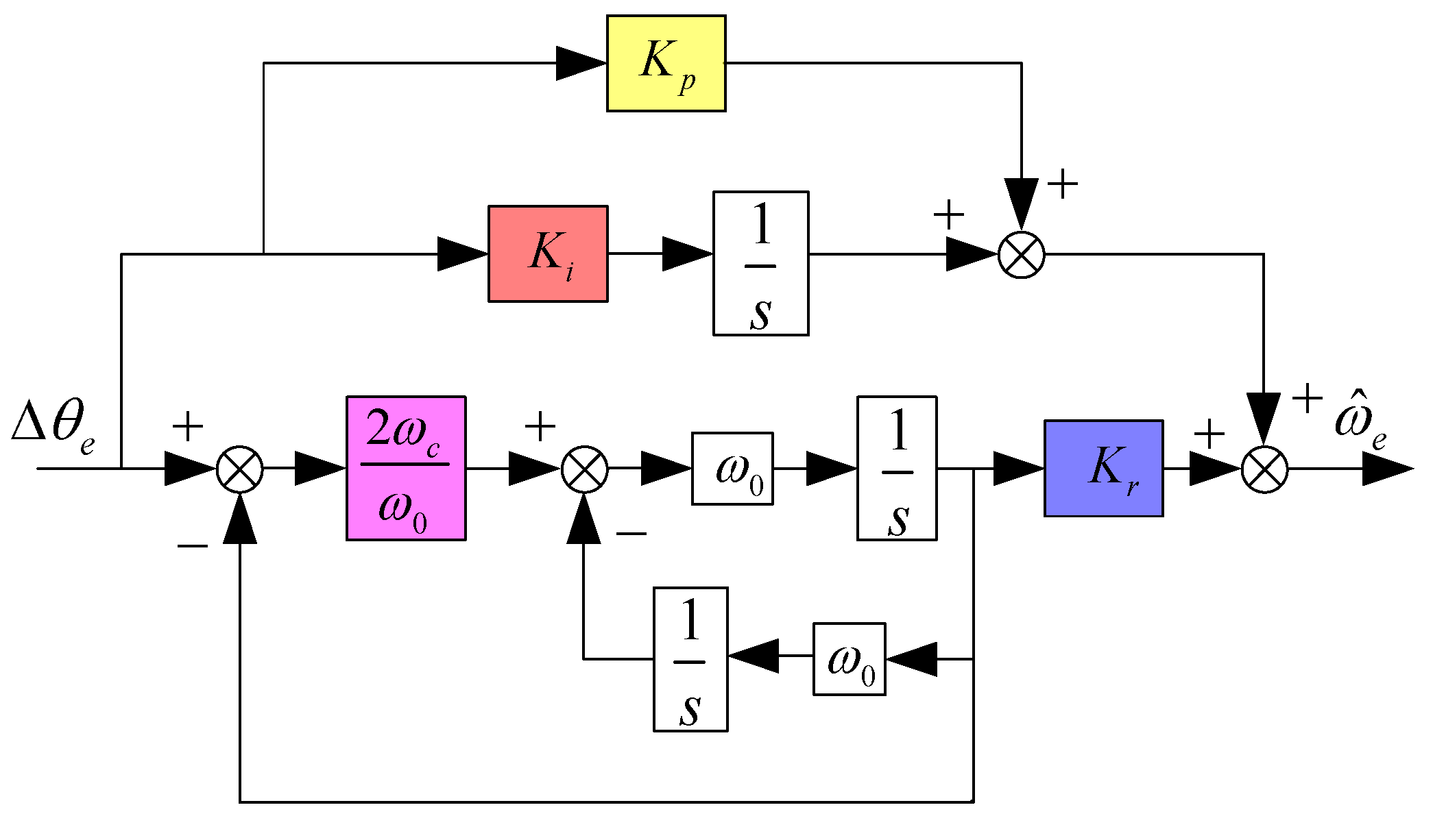
Based on the internal model principle, the resonance controller can be used to track alternating signals without any steady-state errors. Thus the PIR controller [42] can be adopted to replace the PI controller in order to eliminate the tracking error. The block diagram of the PIR controller is shown in Figure 8.

Figure 8.
Block diagram of the proportional-integrational-resonant (PIR) controller.
The transfer function can be expressed as
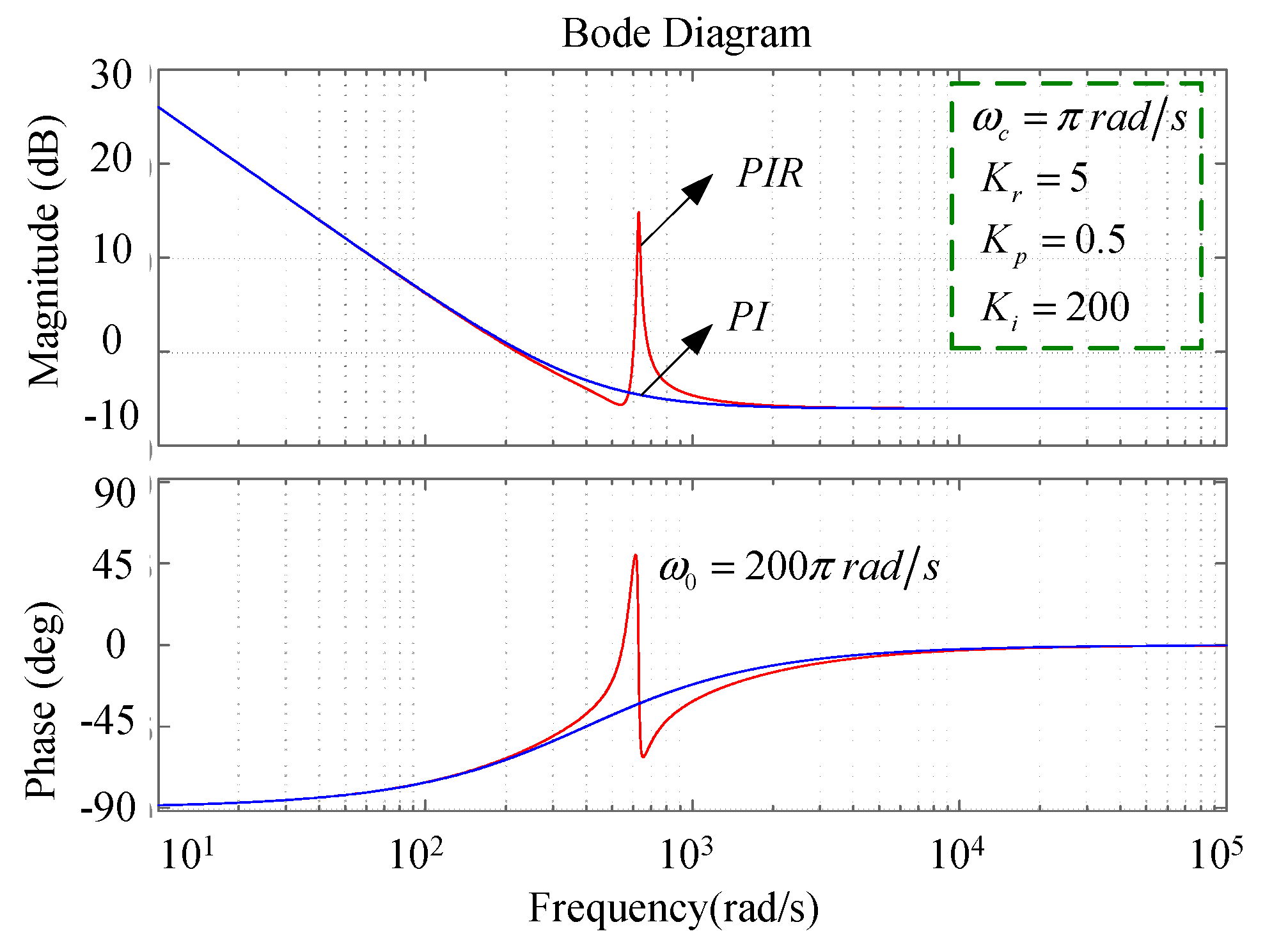
where Kp is proportional gain, Kr is resonant gain, ωc is cutoff frequency, Ki denotes the integral gain, and ω0 is resonant frequency, which is 200π rad/s when the grid frequency is 50 Hz. The PIR controller combines the advantages of PI controller and resonance controller. For example, the dc component in speed estimation is controlled by the PI controller, and the sinusoidal AC component is regulated by the resonance controller. The PIR controller replaces the PI controller to eliminate the tracking error of speed and position estimations. The Bode diagrams of the PI and PIR controllers are shown in Figure 9.
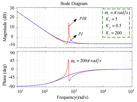
Figure 9.
Bode diagrams of the PI and PIR controllers.
It is obvious that the PI controller has high gain at low frequency. As frequency increases, the gain becomes smaller, and the bandwidth is too small to regulate the 100 Hz sinusoidal signal. On the contrary, the PIR controller has high gain at the resonant frequency, and it decreases sharply away from the resonant frequency until it coincides with the PI controller. Optimized performance with overall frequency range is achieved. The dc component and AC component of the estimate speed are facilitated to be fast tracked by the PIR controller.
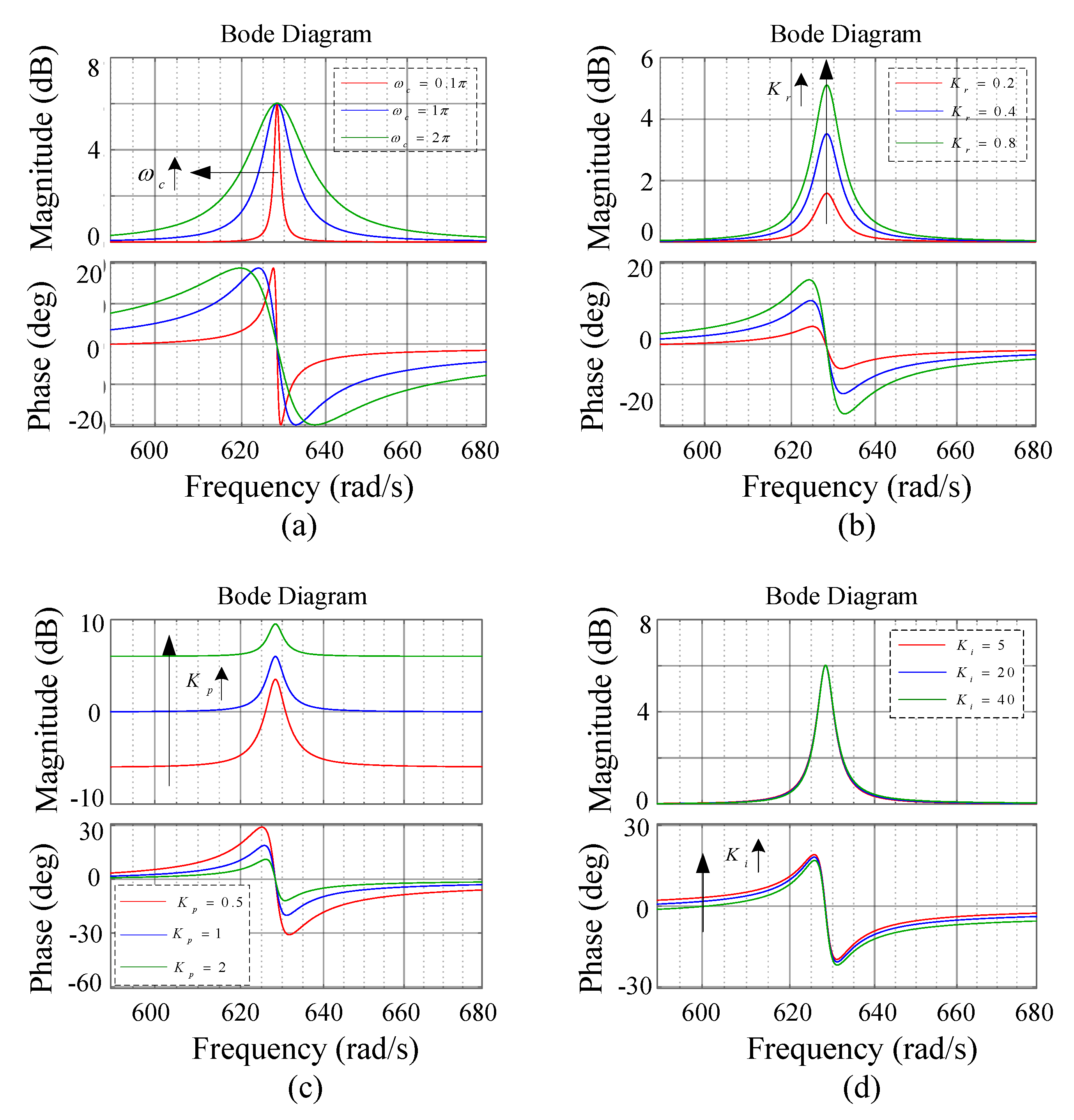
Besides the gain, the other parameters also affect the controller performance. According to Equation (21), there are four main parameters, Kp, Ki, Kr, and ωc. The frequency response output of the PIR controller under different parameters are shown in Figure 10. Figure 10a shows the frequency response output of the PIR controller under different values of ωc, such as 0.2π rad/s, 1π rad/s, and 2π rad/s. ωc is the frequency width of the resonant control, which does not influence the controller gain. As the resonant frequency is a constant value, ωo = 200π, the width should be set as small as possible. In order to ensure the dynamic performance and filter out the harmonic components, the ωc should be set as a proper value. Figure 10b shows the frequency response output of the PIR controller under different values of Kr, such as Kr = 0.2, 0.5, and 0.8. The Kr only determines the gain of resonant frequency. When it increases, the gain increases. But the phase angle and the resonant width remain constant. The Kr could be set by the amplitude error of the motor estimate and actual speed. Figure 10c shows the frequency response output of the PIR controller under different values of Kp, such as Kp = 0.5, 1, and 2. The Kp has effects on the overall frequency range, and the gain increases when Kp increases. Figure 10d shows the frequency response output of the PIR controller under different values of Ki, such as Ki = 5, 20, and 40. This affects the phase of the controller, and the delay time decreases when Ki increases outside of the resonant frequency bound. The magnitude curves coincide together.
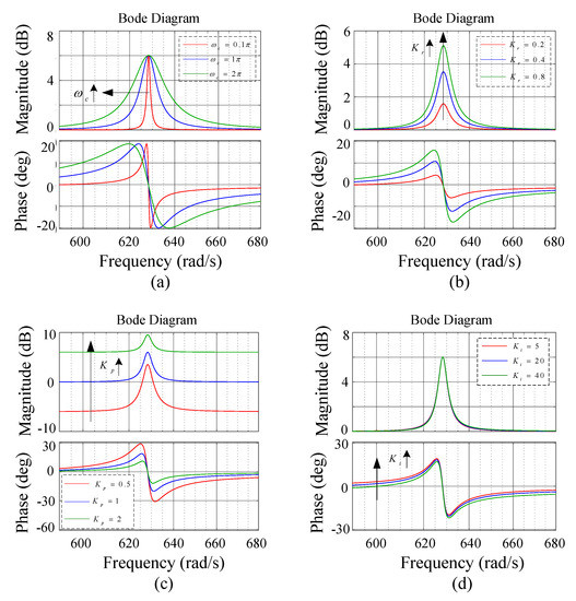
Figure 10.
Frequency response output of the PIR controller. (a) ωc; (b) Kr; (c) Kp; (d) Ki.
Based on the above analysis of the PIR controller characteristics, the dc component can be controlled by ωc and Kr, and the AC component can be controlled by Kp and Ki. The suitable parameters would ensure the speed estimate tracking performance and position estimate error of the estimator. The control block diagram of the proposed estimator based on the quadrature PLL can be seen in Figure 11, where is actual position, is estimated speed and is estimated position.
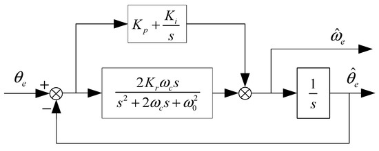
Figure 11.
Control block diagram of the proposed estimator.
The equivalent open loop transfer function of the estimator can be given by
where Kp is the equivalent open-loop gain of the estimator, τr = Kr/Kp is the equivalent resonant coefficient, and τi = Ki/Kp is relative to the integral time constant. In order to analyze the estimator stability and adjust the controller parameters, the sampling time is set to 10 μs, and Equation (22) is transferred into discrete time domain. The root locus of the close-loop when Kp changes from zero to infinite is shown in Figure 11. Obviously, while the ωc, τr, and τi changes, the closed-loop characteristic roots can be located inside the unit circle boundary in the z plane, which indicates a stable system.
In Figure 12a, when τi =15 and τr =10, the root locus comes together with different ωc, such as ωc = 0.2π rad/s, 4π rad/s, and 20π rad/s. Therefore, the ωc has less effects on the estimator system. To eliminate unexpected harmonics, the bandwidth ωc must to be set small [17], and it can be designed as 4π rad/s, which relates to the AC component in the estimated speed.
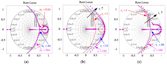
Figure 12.
Root locus of the estimator based on PIR controller. (a) ωc; (b) τi; (c) τr.
In Figure 12b,c, the characteristic roots move toward to the outside of the unit circle, and the stability margin weakens, while τi and τr increase. This indicates that the integral control enhances, and overshoot of the estimator increases. Thus, the proportional gain Kp should be selected as Kp < 1.24.
Therefore, the damping ratio is usually selected to be around 0.707 [40], and the overshoot of the estimator is configured below 10%. Then, parameters of the PIR controller were selected as Kp = 0.5, Ki = 15, Kr = 10, and ωc = 4π rad/s.
On the basis of the above analysis, it can be concluded that the proposed estimator has low magnitude attenuation and phase delay at the resonant frequency point. Rapid response can be achieved to ensure dynamic performance of the sensorless control system as well.
4. Simulation and Experimental Results
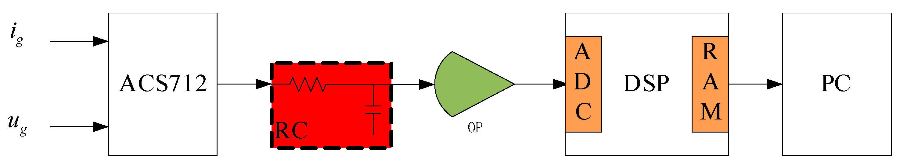
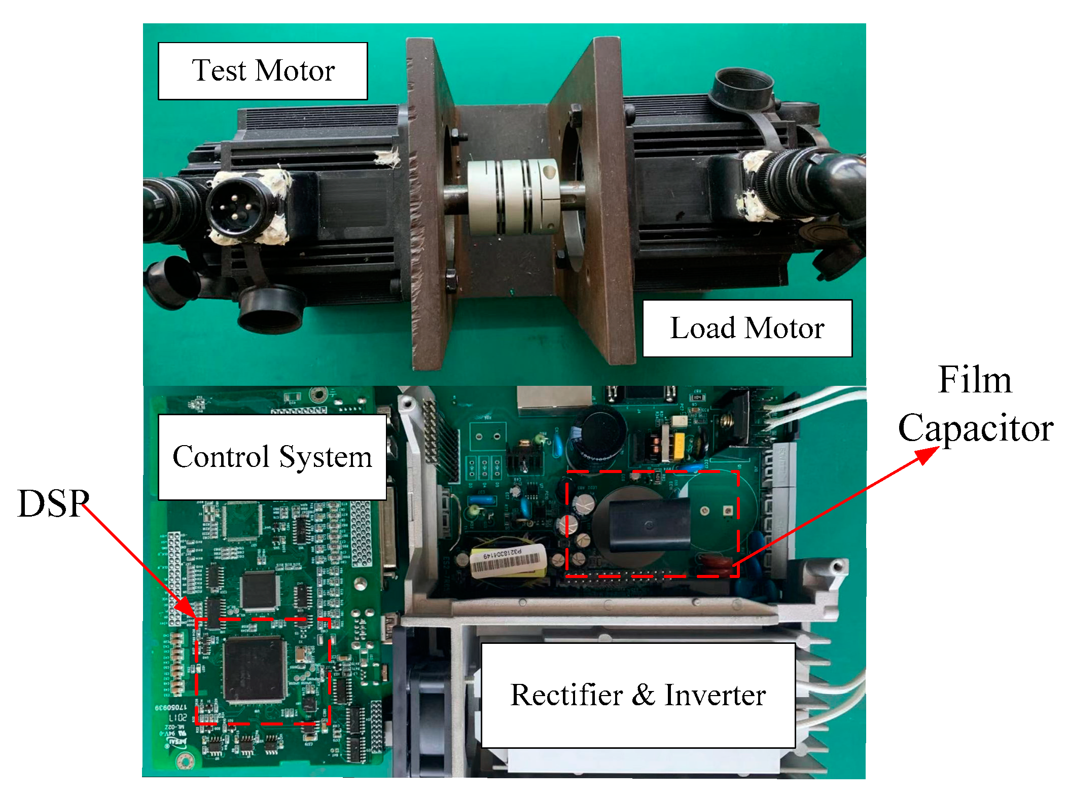
In order to verify the effectiveness of the proposed control method, simulation and experiments were both carried out. Figure 13 shows grid input voltage and current sample circuits. The motor and the system parameters are listed in Table 1. The experimental hardware is shown in Figure 14. The load motor was used as a generator and consumed power at a load resistor. A position encoder TS5700N8401 was installed on the motor to detect the actual position and speed of the motor for comparison. The inverter was realized by Mitsubishi module PS21767. The proposed control method was implemented with a Texas Instruments TM320F28075 floating-point digital signal processor.

Figure 13.
Grid input voltage and current sample circuits.

Table 1.
Drive and system parameters.
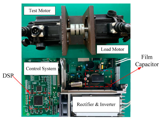
Figure 14.
Experiment hardware configuration.
In the system, the DC-link capacitor Cdc was only 8 μF, the speed and current controller adopted the PI regulator, and the bandwidth was set lower than the electronic capacitor drives to ensure the stability of the system. A power controller was cascaded between the speed and current controllers to control the grid power factor and suppress the input current harmonics [21]. Therefore, the proposed SMO control method in this system should not only reduce the position estimation error, but also shape the estimated speed to track the actual speed as much as possible. This would improve the grid input performance of the small DC-link capacitor drive system. In this paper, the average voltage constraint in [16] was applied for such system to obtain a high power factor. The average DC-link voltage can be calculated as follow [43]:
Since the maximum speed of motor is about 3900 r/min, the maximum average speed is about 3900 × 2/π = 2500 r/min. Similarly, according to Equation (7), the ideal output torque of the motor can be obtained by:
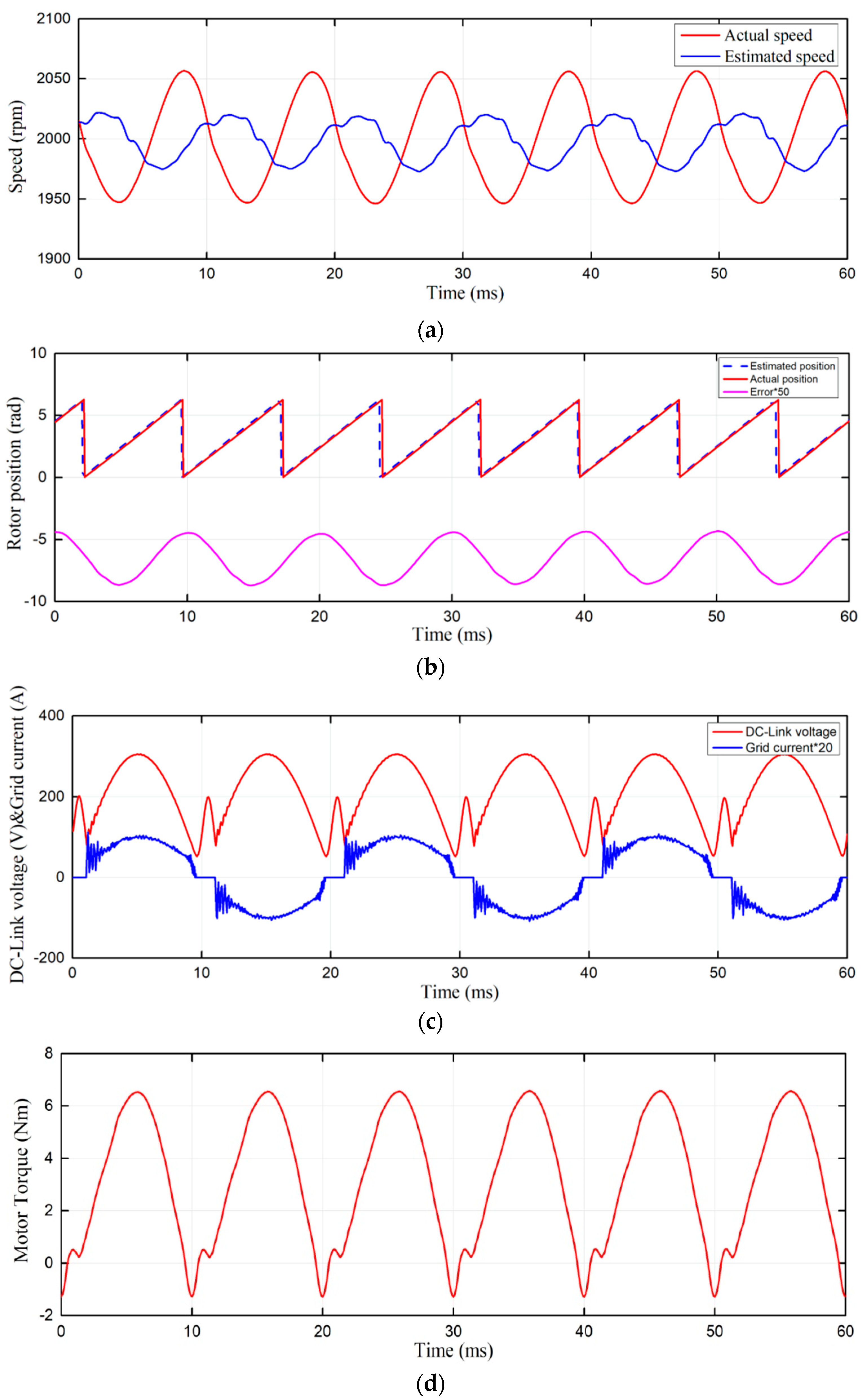
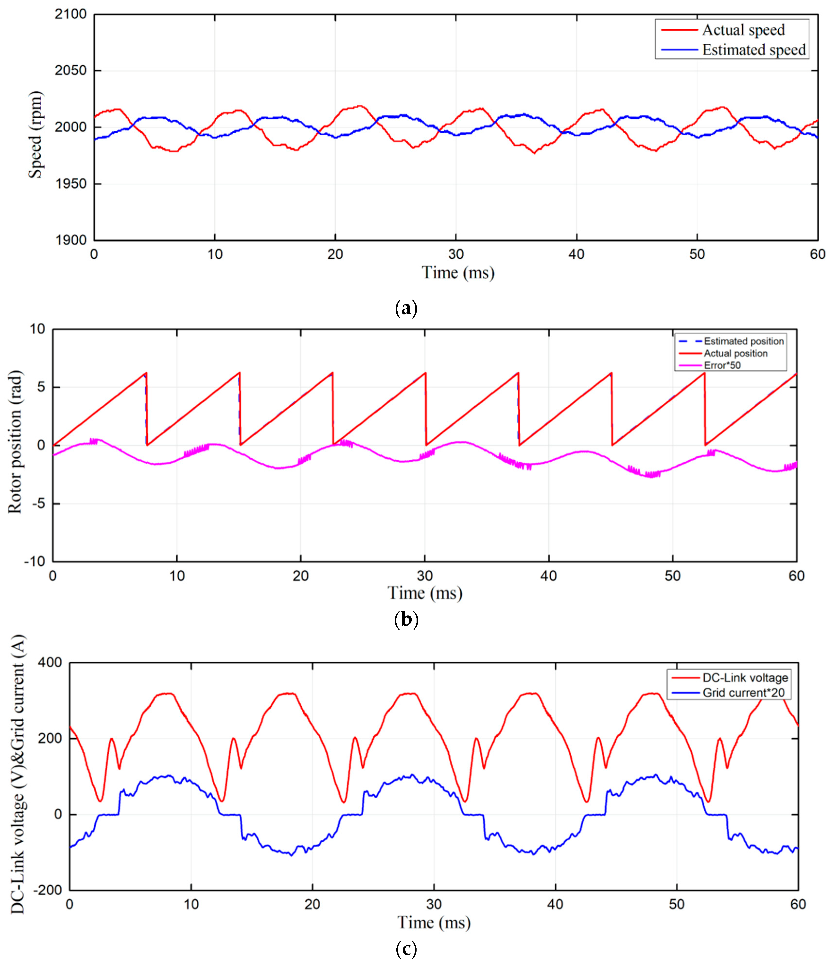
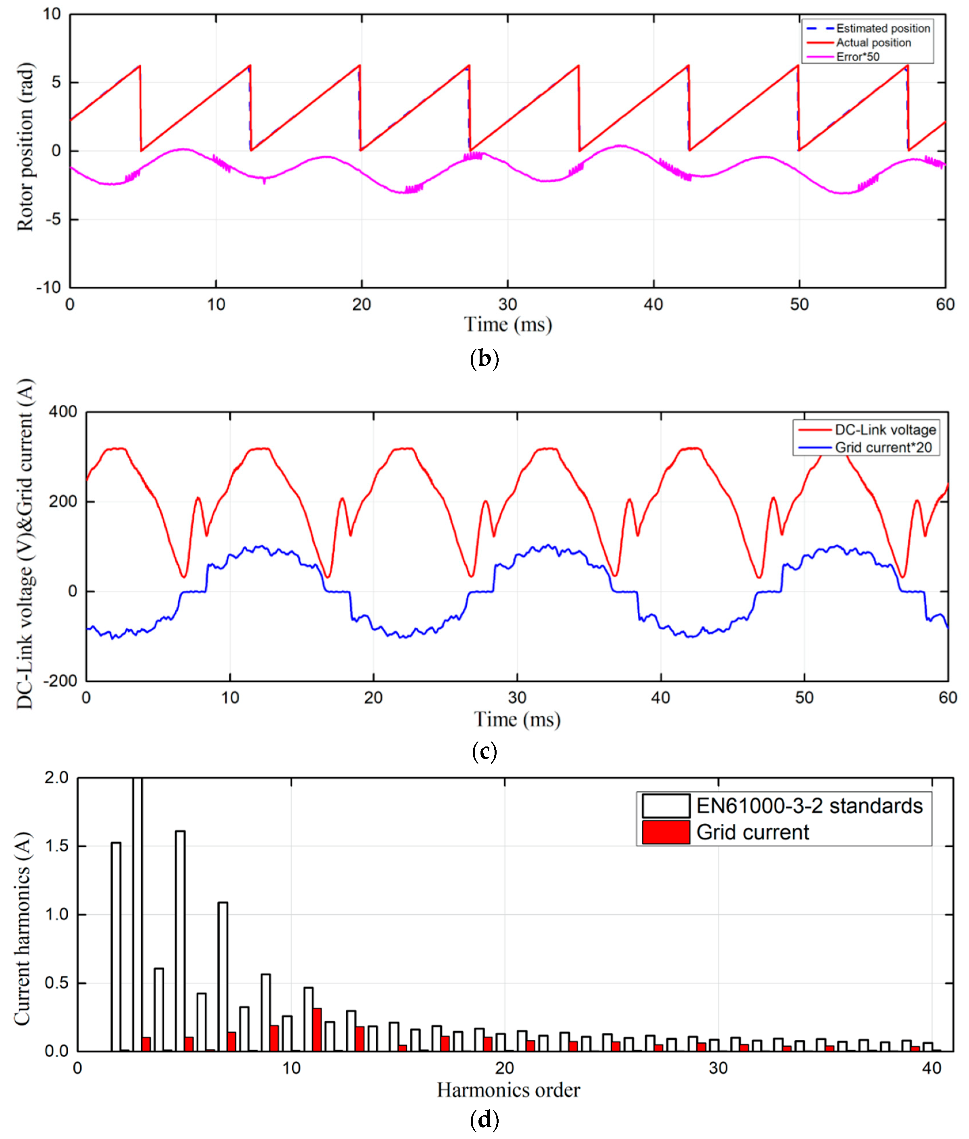
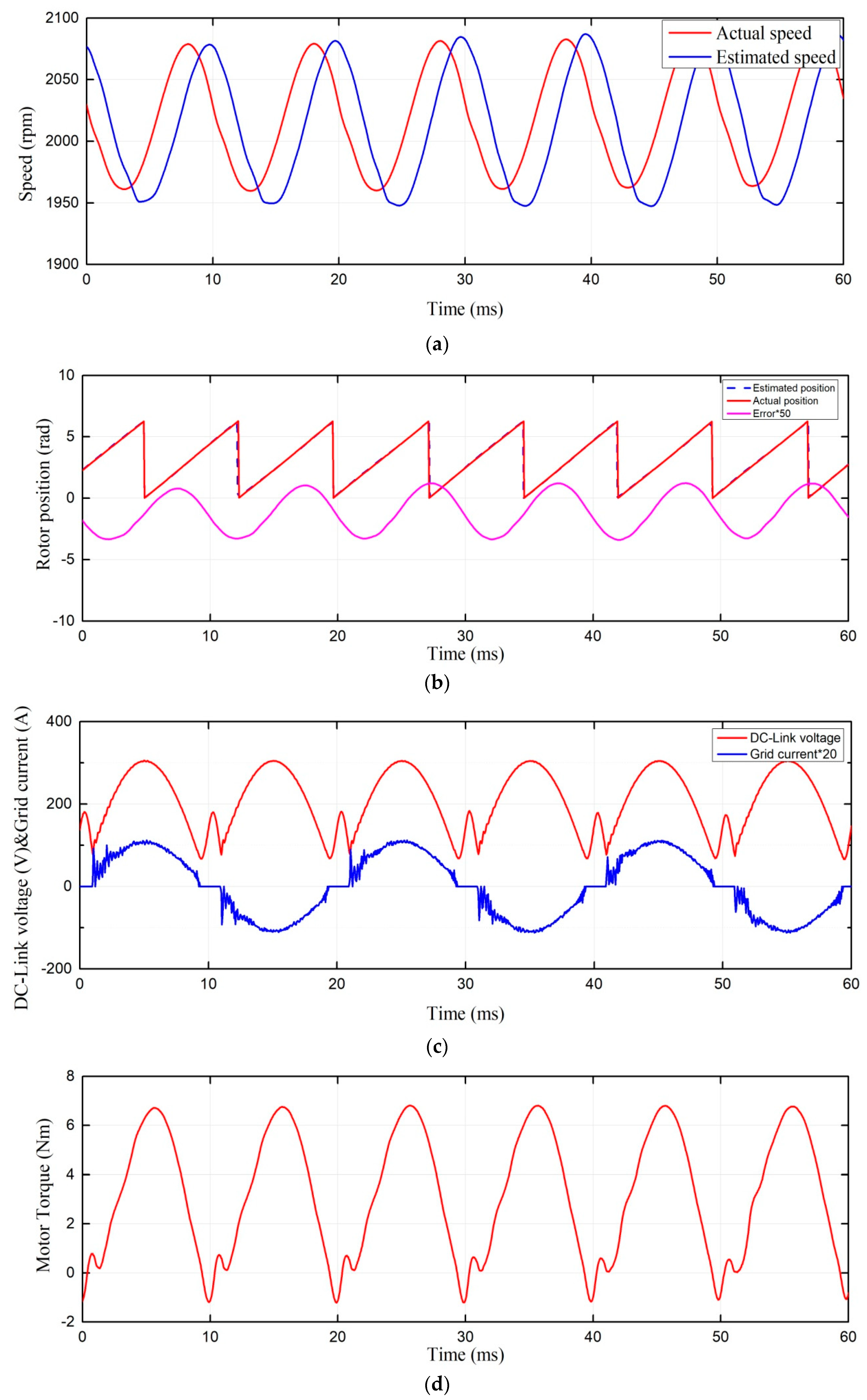
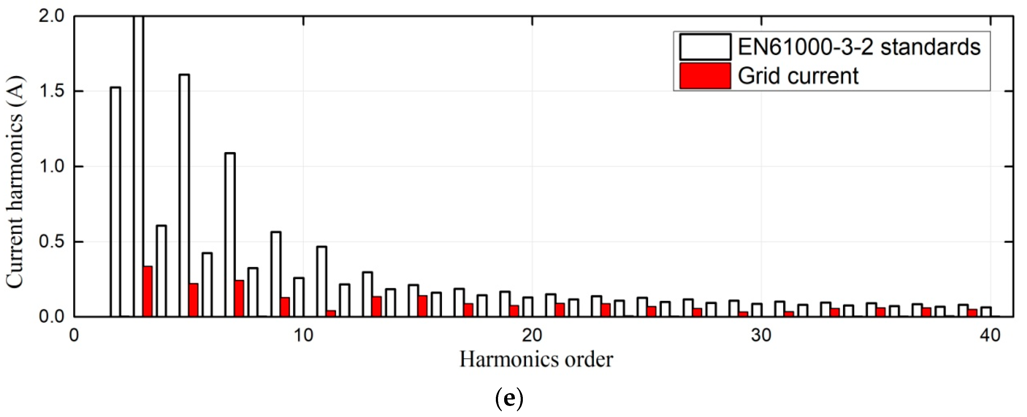
The average torque is 3.2 Nm; all of these simulations and experiments were at 3.2 Nm and 2000 r/min. Detailed analysis of the results is illustrated as follows. Figure 15 and Figure 16 show the simulation and experimental results for the conventional SMO estimated method. The red curves are actual speed and position of the motor shaft, while the blue curve is the estimated speed and position. Obviously, the motor speed was sinusoidal, with two times the grid voltage frequency, and the estimated speed delay to the actual speed was about 3 ms, so that the position estimated error was also sinusoidal and changed from −8° to −5°. Under a low estimation bandwidth, the amplitude was only half of the actual speed, and the bandwidth of speed estimation was low. On the grid side, the power factor was 99.48%. In Figure 13, the grid input current oscillates when crossing zero, causing higher harmonics than experimental result. In Figure 15c, the grid input current is smooth, because the hall sensor and low pass filter (RC) shown in Figure 13 filter out a lot of higher order harmonics, such as the switching noise of IGBT. The distribution of the harmonics complied with the simulation result.
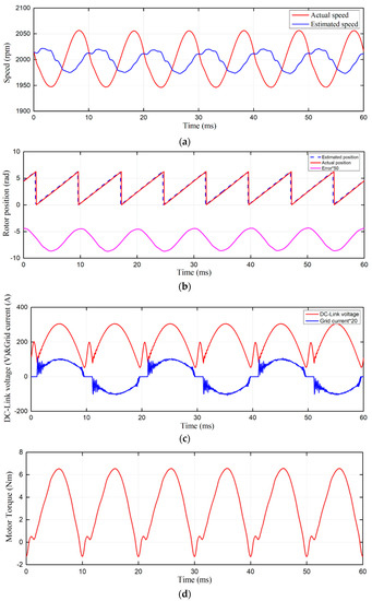
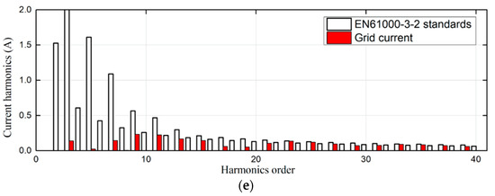
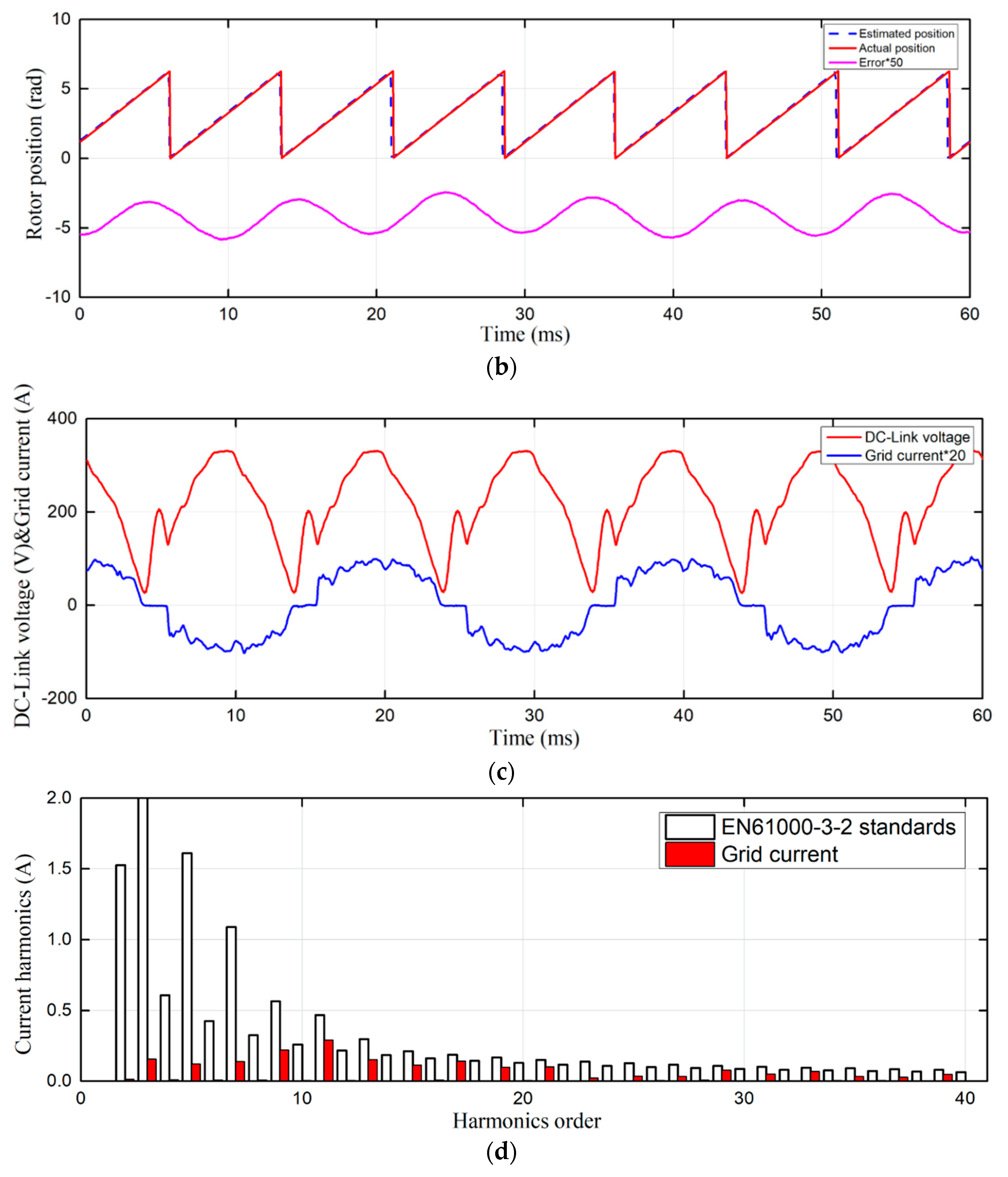
Figure 15.
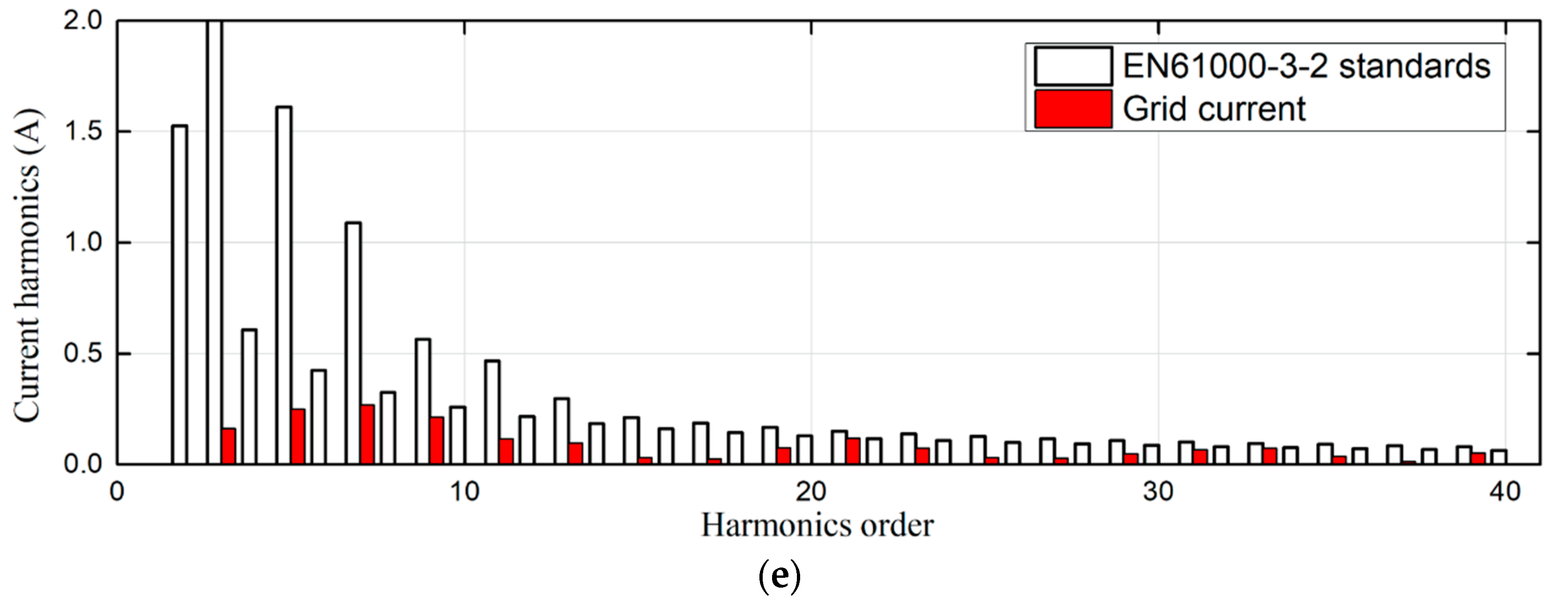
Simulation result of the conventional SMO estimate method with a PI controller: (a) Motor Speed; (b) Position and estimated error; (c) DC-link voltage and grid current; (d) Motor output torque; (e) FFT analysis of grid current.
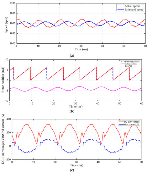
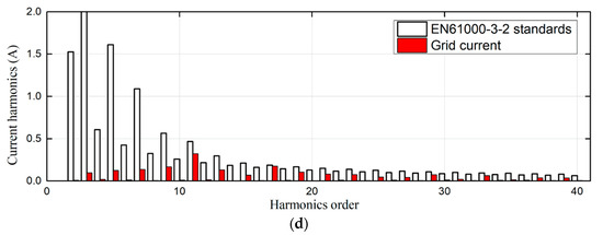
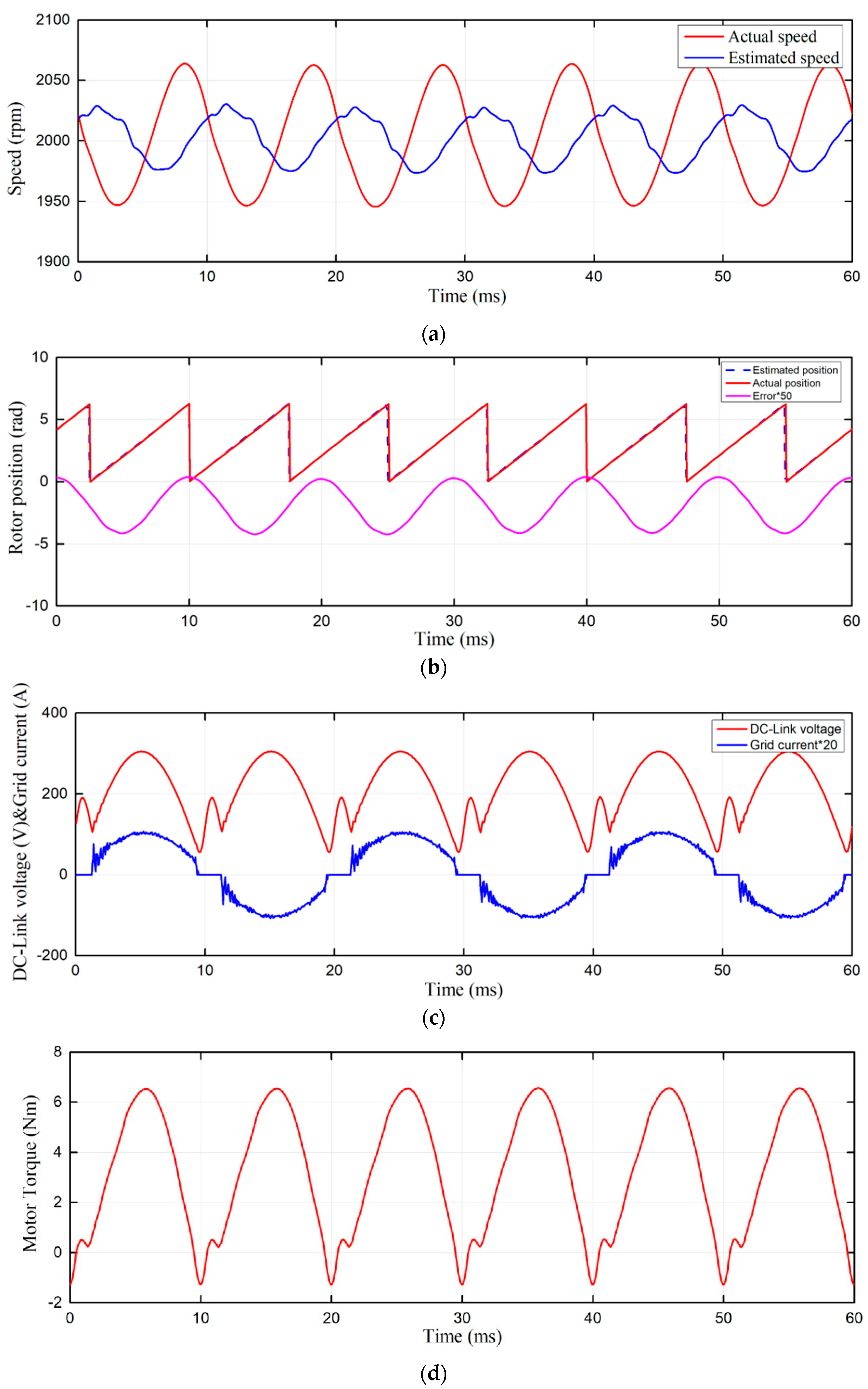
Figure 16.
Experimental results of the conventional SMO estimate method with a PI controller: (a) Motor Speed; (b) Position and estimated error; (c) DC-link voltage and grid current; (d) FFT analysis of grid current.
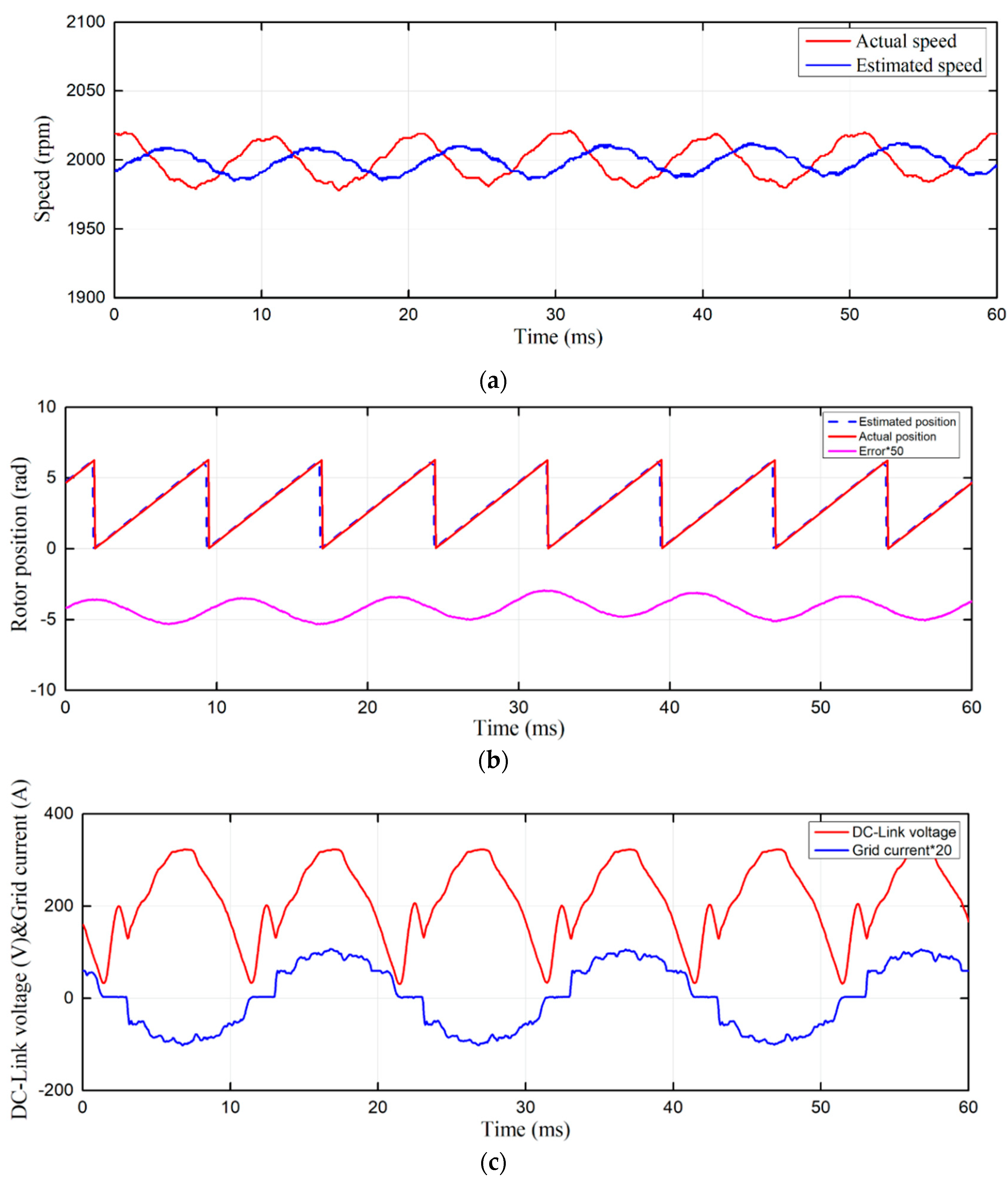
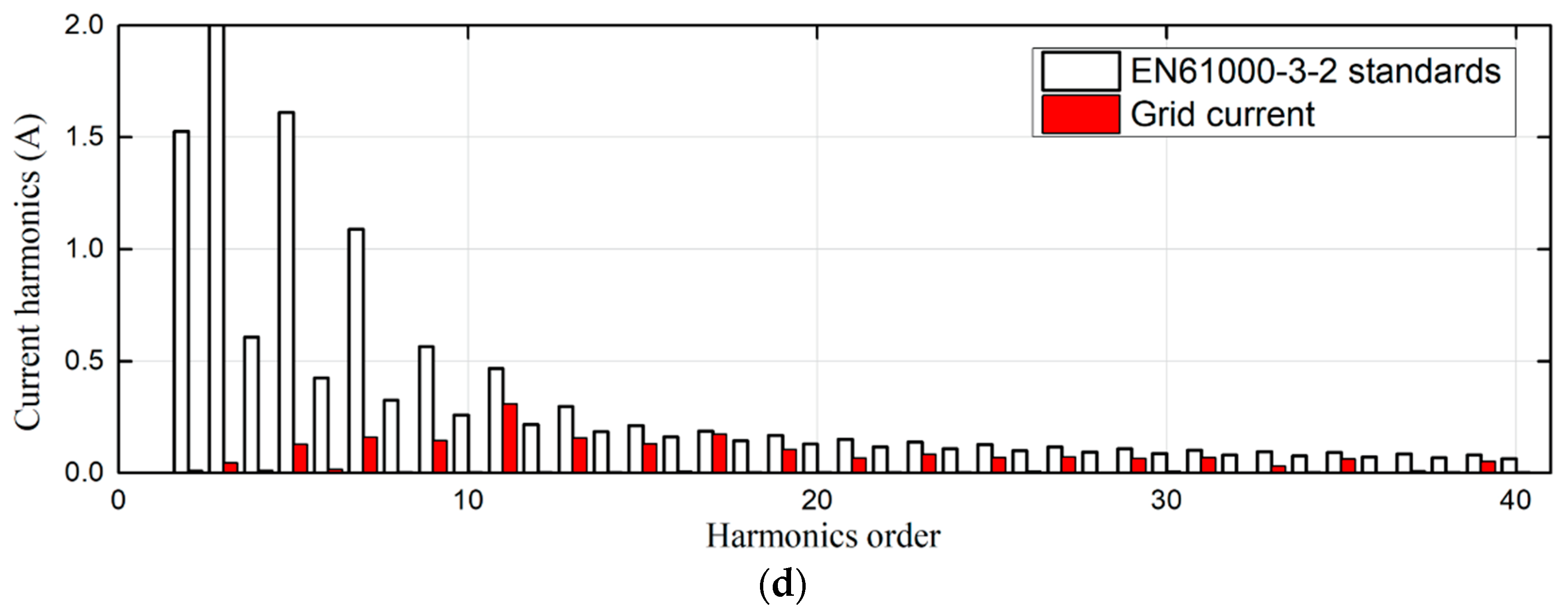
In the small DC-link capacitor drive system, the conventional SMO estimate method generates a lot of problems. As shown in Figure 17 and Figure 18, the PI controller in software PLL is replaced by a PIR controller. The resonant frequency, width and gain were set as 100 Hz, 3 Hz and 6, respectively. When the frequency of the actual speed is a constant value, the resonant controller can be regarded as feedforward compensation for the estimated speed. As shown in Figure 16, the phase delay time behind the estimated speed is about 2 ms, the amplitude can reach the actual speed, the dynamic error of the estimated position reduces. In Figure 17, the experimental speed cannot be completely consistent with the simulation due to the changes and disturbances of the loads. Therefore, the speed and current control gain should be set lower to ensure the stability of the system, and that the estimated time delay is bigger than the simulation result.
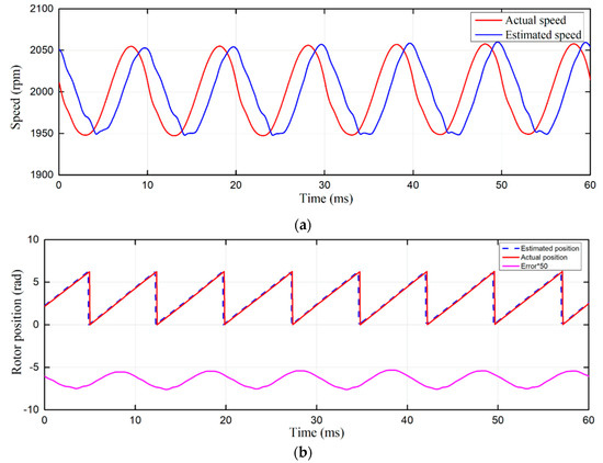
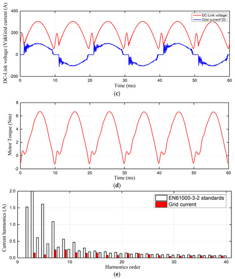
Figure 17.
Simulation of conventional SMO only with a PIR controller: (a) Motor Speed; (b) Position and estimated error; (c) DC-link voltage and grid current; (d) Motor output torque; (e) FFT analysis of grid current.

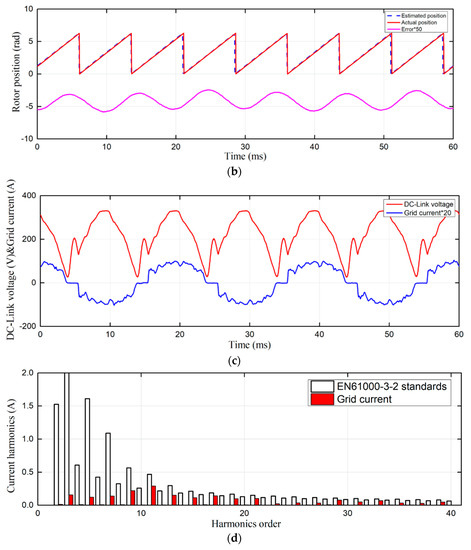
Figure 18.
Experiment with conventional SMO only with a PIR controller: (a) Motor Speed; (b) Position and estimated error; (c) DC-link voltage and grid current; (d) FFT analysis of grid current.
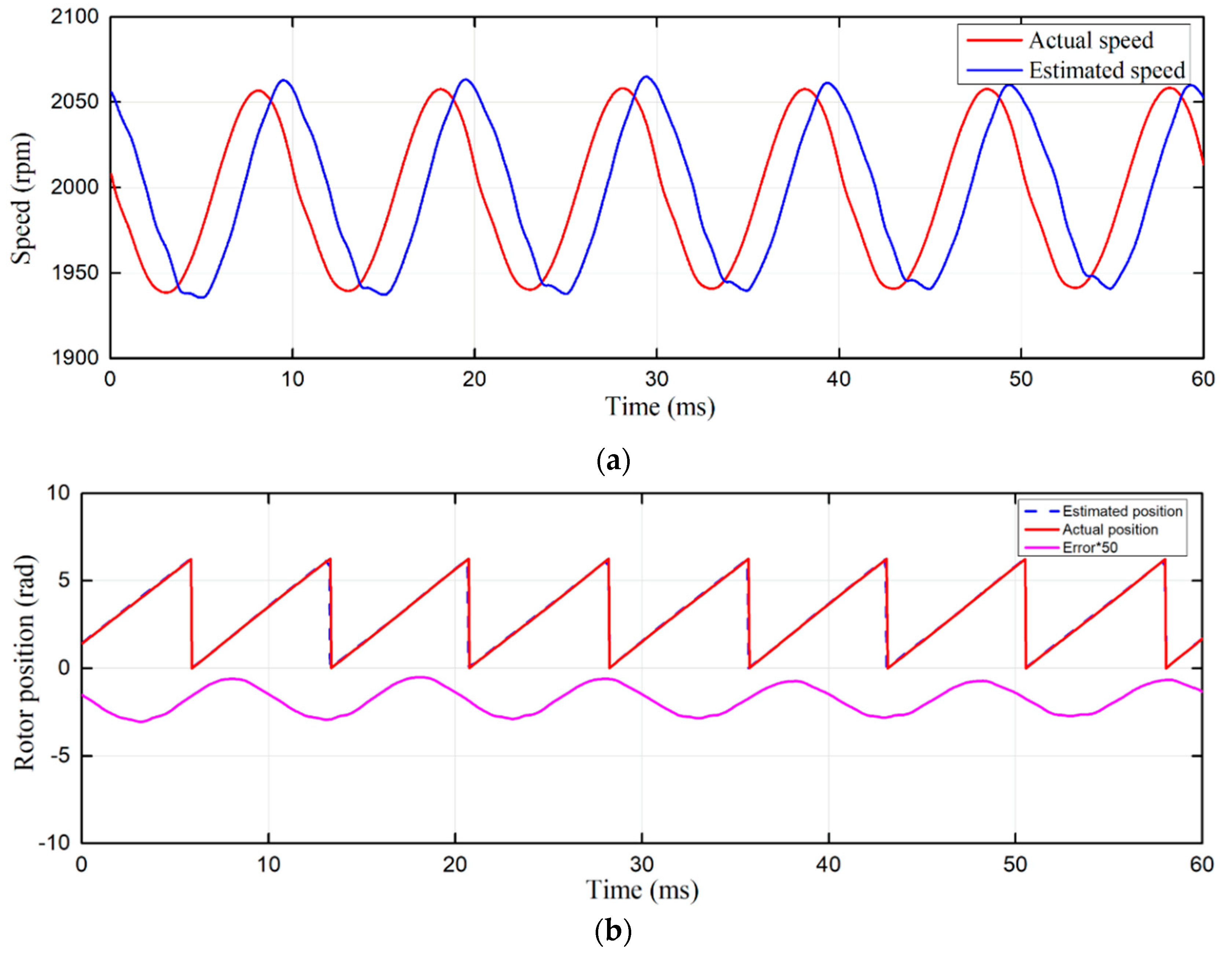
Figure 19 and Figure 20 show the FSMO estimation method with a PI controller. The execution time was only 10 us, which means SMO is executed 5 times in one current control cycle. Consequently, the sample time of the motor phase currents and the DC-link voltage can be reduced. On the other side, the back EMF voltage eα and eβ estimation became more smooth. Hence, the low-pass filter, which aimed at smoothing estimated back EMF, could be eliminated. The delay of the estimated speed decreased, the estimated position could actually be tracked well, and the steady-state error of position estimation was reduced to 0°–3°. The input current oscillation at the grid side was reduced, and the harmonic component could basically meet the EN61000-3-2 standards.
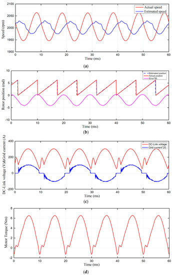

Figure 19.
Simulation result of the FSMO estimate method with a PI controller: (a) Motor Speed; (b) Position and estimated error; (c) DC-link voltage and grid current; (d) Motor output torque; (e) FFT analysis of grid current.
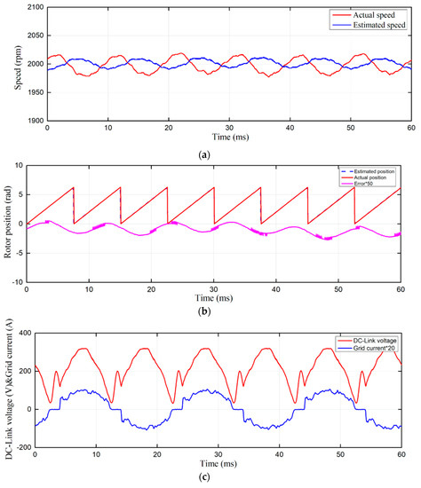

Figure 20.
Experimental result of the FSMO estimate method with a PI controller: (a) Motor Speed; (b) Position and estimated error; (c) DC-link voltage and grid current; (d) FFT analysis of grid current.
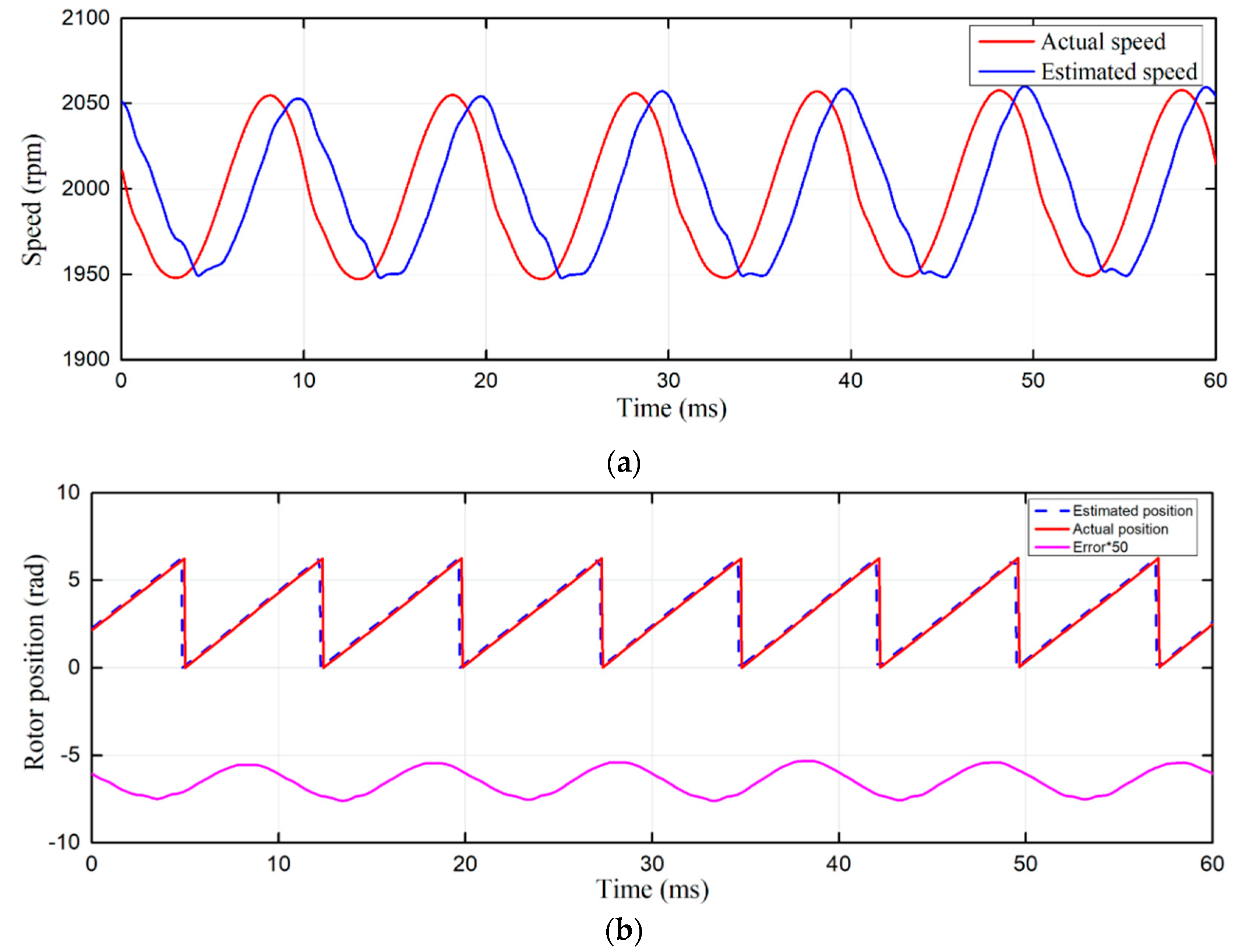
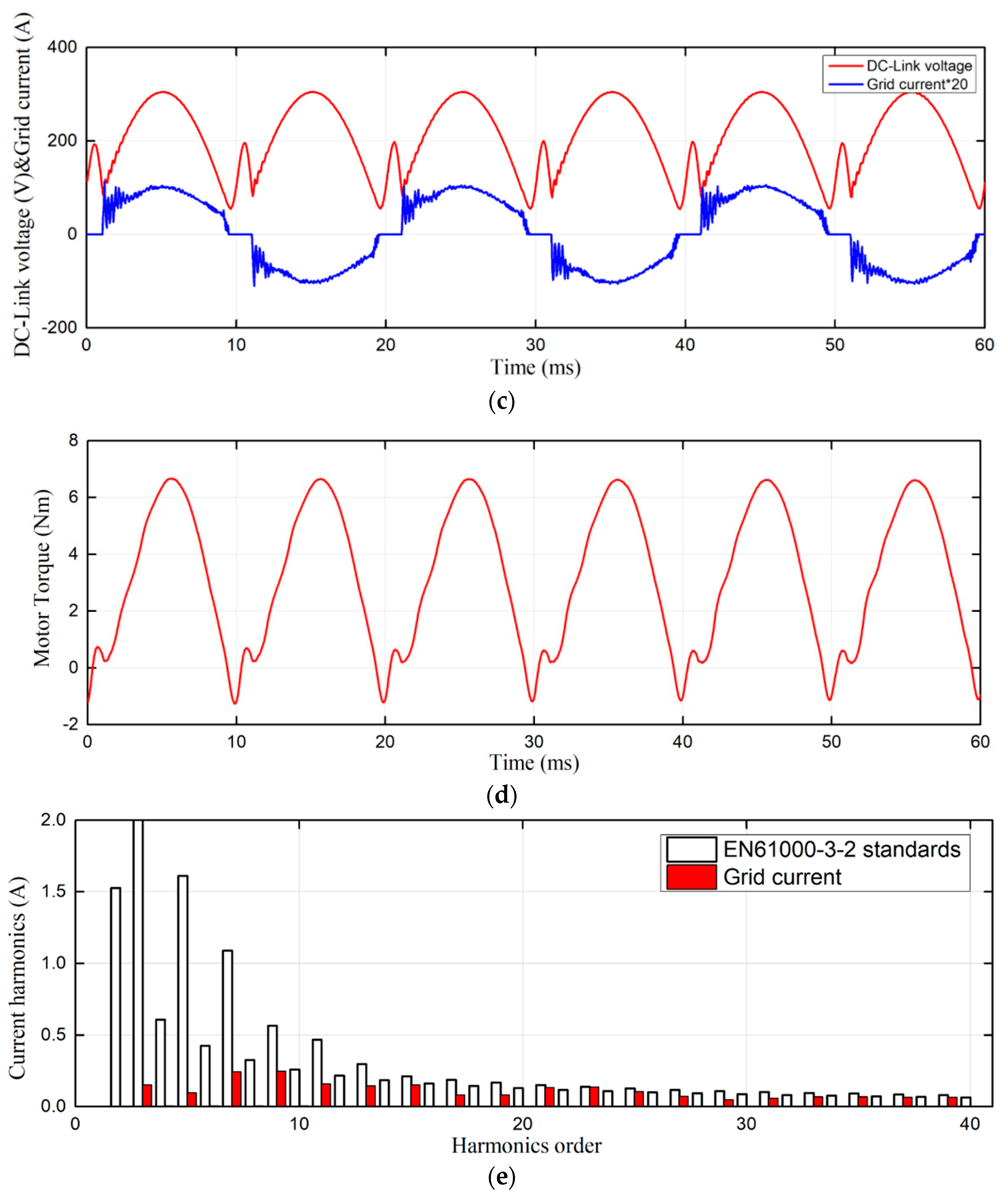
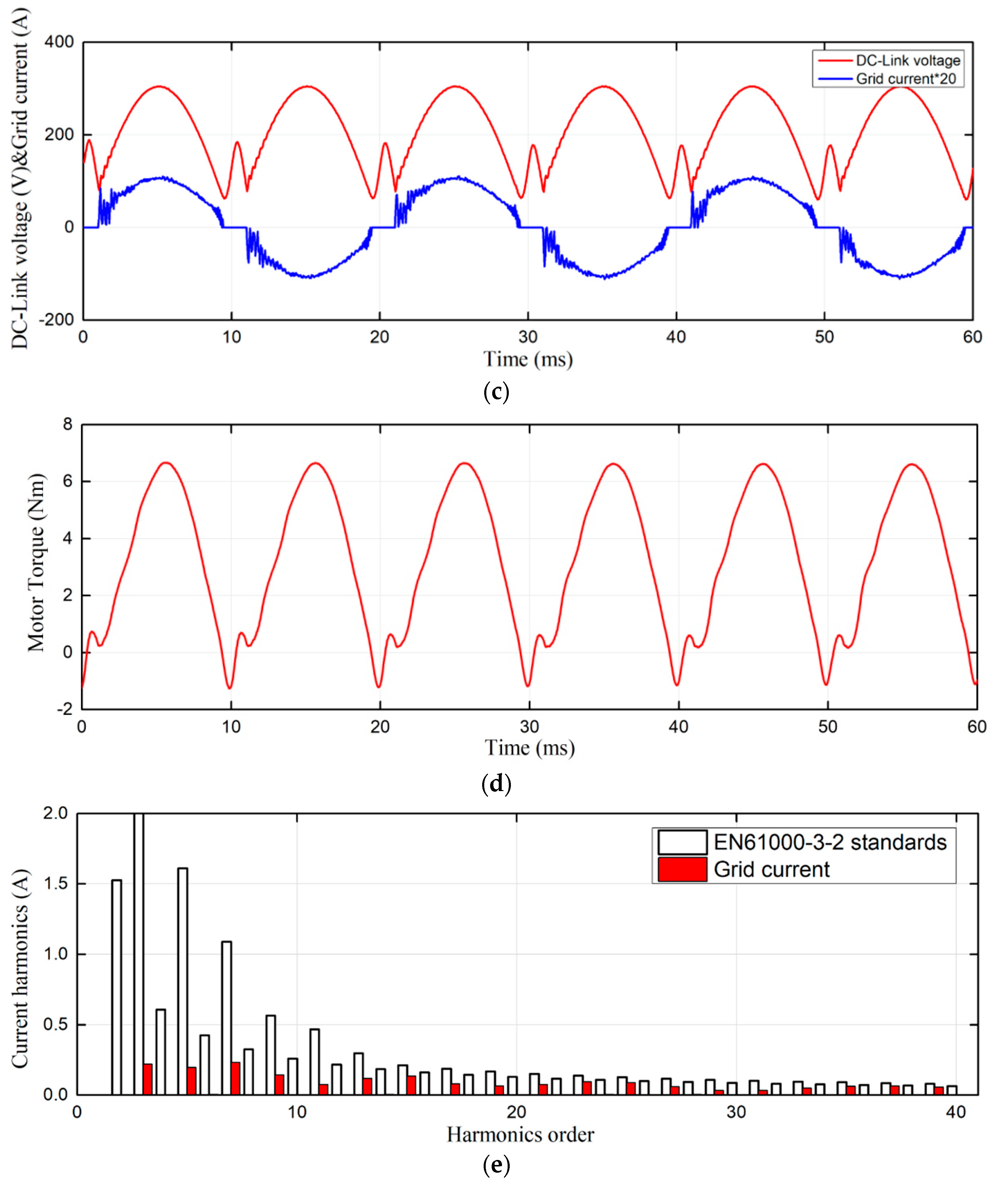
According to the above analysis, the PLL based on PIR controller can reduce the position dynamic error, and FSMO can reduce the position steady-state error. The combination of these two methods is shown in Figure 21 and Figure 22. The estimated amplitude can track the actual speed, and the position estimated error is minimized from 0 to 3°. The grid power factor is as high as 99.65%. The input current harmonics are smaller than the FSMO method in Figure 19, especially the higher harmonic component. This meets the EN61000-3-2 standards better.
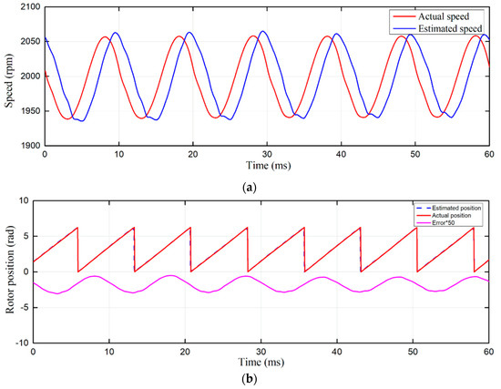
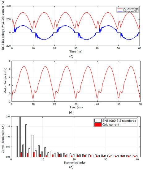
Figure 21.
Simulation result of the FSMO estimate method with a PIR controller: (a) Motor Speed; (b) Position and estimated error; (c) DC-link voltage and grid current; (d) Motor output torque; (e) FFT analysis of grid current.
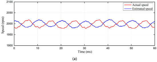

Figure 22.
Experimental result of the FSMO estimate method with a PIR controller: (a) Motor Speed; (b) Position and estimated error; (c) DC-link voltage and grid current; (d) FFT analysis of grid current.
To verify parameter robustness of the proposed control method, the observer parameters were changed to simulate variation of the motor parameters. As shown in Figure 23, the resistance decreased 25% and inductance increased 10%. When the observer parameters vary, the observer and estimator can operate stably, and the position as well as speed estimations do not deteriorate visibly. That is to say, the proposed control system has a good robustness to the parameters.
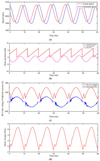
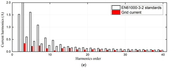
Figure 23.
Simulation result of the proposed control method under observer parameter variation: (a) Motor Speed; (b) Position and estimated error; (c) DC-link voltage and grid current; (d) Motor output torque; (e) FFT analysis of grid current.
In the simulation and experimental results, it can be seen that the IPMSM drive with the proposed sensorless vector control method exhibits satisfactory performance, adopting a DSP control scheme.
5. Conclusions
In this paper, an improved sensorless vector control method for an IPMSM drive has been proposed in the small DC-link capacitor drive system. For reduced capacity at the DC-link bus, the traditional SMO can’t meet the position and speed estimation performance, and also affects the grid power factor and input current harmonics. The FSMO reduced the position-estimated steady-state error, and the dynamic error has been reduced by replacing the PI with a PIR regulator in the software quadrature PLL. When controller stability is analyzed utilizing the root locus diagram, the estimated speed is closer to the actual speed. The power factor can reach 0.996, and the total harmonic distortion of the gird current can meet the recommendations of EN61000-3-2. Experimental results demonstrated that the proposed improved sensorless vector control method not only effectively reduces the position error, but also improves grid input performance for small DC-link capacitor drive systems. Nevertheless, different loads resulted in different speed fluctuation ranges, worsening the system performance and causing power grid pollution because of the increased harmonics. Thus, future work involves expanding the drive system to different loads, the acoustic noise of the motor, and focusing on the estimator error caused by other harmonics in the back EMF.
Author Contributions
Conceptualization, Q.Y.; methodology, Q.Y. and H.L. (Haichun Li); software, H.L. (Hui Luo); validation, Q.W. and C.X.; investigation, H.L. (Haichun Li); writing—original draft preparation, H.L. (Haichun Li) and C.X. All authors have read and agreed to the published version of the manuscript.
Funding
This research was funded by the National Natural Science Foundation of China, grant number 61374049.
Conflicts of Interest
The authors declare no conflict of interest.
References
- Dutta, R.; Rahman, M.F. Design and analysis of an interior permanent magnet (IPM) machine with very wide constant power operation range. IEEE Trans. Energy Convers. 2008, 23, 25–33. [Google Scholar] [CrossRef]
- Jung, S.; Mi, C.C.; Nam, K. Torque control of IPMSM in the field-weakening region with improved DC-Link voltage utilization. IEEE Trans. Ind. Electron. 2015, 62, 3380–3387. [Google Scholar] [CrossRef]
- Tinazzi, F.; Zigliotto, M. Torque estimation in high-efficency IPM synchronous motor drives. IEEE Trans. Energy Convers. 2015, 30, 983–990. [Google Scholar] [CrossRef]
- Chen, Z.Q.; Tomita, M.; Doki, S.; Okuma, S. An extended electromotive force model for sensorless control of interior permanent magnet synchronous motors. IEEE Trans. Ind. Electron. 2003, 50, 288–295. [Google Scholar] [CrossRef]
- Wang, G.; Yang, R.; Xu, D. DSP-based control of sensorless IPMSM drives for wide-speed-range operation. IEEE Trans. Ind. Electron. 2013, 60, 720–727. [Google Scholar] [CrossRef]
- Sun, Y.; Preindl, M.; Sirouspour, S.; Emadi, A. Unified wide-speed sensorless scheme using nonlinear optimization for IPMSM drives. IEEE Trans. Ind. Electron. 2017, 32, 6308–6322. [Google Scholar] [CrossRef]
- Luo, X.; Tang, Q.; Shen, A.; Shen, H.; Xu, J. A combining FPE and additional test vectors hybrid strategy for IPMSM sensorless control. IEEE Trans. Power Electron. 2018, 33, 6104–6113. [Google Scholar] [CrossRef]
- Luo, X.; Tang, Q.; Shen, A.; Shen, H.; Zhang, Q. PMSM sensorless control by injecting HF pulsating carrier signal into estimated fixed-frequency rotating reference frame. IEEE Trans. Ind. Electron. 2016, 63, 2294–2303. [Google Scholar] [CrossRef]
- Bernardes, T.; Montagner, V.F.; Grundling, H.A.; Pinheiro, H. Discrete-time sliding mode observer for sensorless vector control of permanent magnet synchronous machine. IEEE Trans. Ind. Electron. 2014, 61, 1679–1691. [Google Scholar] [CrossRef]
- Wang, G.; Zhan, H.; Zhang, G.; Gui, X.; Xu, D. Adaptive compensation method of position estimation harmonic error for EMF-based observer in sensorless IPMSM drives. IEEE Trans. Power Electron. 2014, 29, 3055–3064. [Google Scholar] [CrossRef]
- Qiao, Z.; Shi, T.; Wang, Y.; Yan, Y.; Xia, C.; He, X. New sliding-mode observer for position sensorless control of permanent-magnet synchronous motor. IEEE Trans. Ind. Electron. 2013, 60, 710–719. [Google Scholar] [CrossRef]
- Son, Y.; Ha, J.I. Direct power control of three phase inverter for grid input current shaping of single phase diode rectifier with small DC-link capacitor. IEEE Trans. Power Electron. 2015, 30, 3794–3803. [Google Scholar] [CrossRef]
- Son, Y.; Ha, J.I. Discontinuous grid current control of motor drive system with single-phase diode rectifier and small DC-link capacitor. IEEE Trans. Power Electron. 2017, 32, 1324–1334. [Google Scholar] [CrossRef]
- Shin, H.; Son, Y.; Ha, J.I. Grid current shaping method with DC-link shunt compensator for three-phase diode rectifier-fed motor drive system. IEEE Trans. Power Electron. 2017, 32, 1279–1288. [Google Scholar] [CrossRef]
- Shin, H.; Son, Y.; Chae, Y.H.; Ha, J.I. Single-phase grid connected motor drive system with DC-link shunt compensator and small DC-link capacitor. IEEE Trans. Power Electron. 2017, 32, 1268–1278. [Google Scholar] [CrossRef]
- Zhao, N.; Wang, G.; Xu, D.; Zhu, L.; Zhang, G.; Huo, J. Inverter power control based on DC-link voltage regulation for IPMSM drives without electrolytic capacitors. IEEE Trans. Power Electron. 2018, 33, 558–571. [Google Scholar] [CrossRef]
- Bao, D.; Pan, X.; Wang, Y. A novel hybrid control method for single-phase-input variable frequency speed control system with a small DC-link capacitor. IEEE Trans. Power Electron. 2019, 34, 9016–9032. [Google Scholar] [CrossRef]
- Kwak, B.; Um, J.H.; Seok, J.K. Direct active and reactive power control of three-phase inverter for AC motor drives with small DC-link capacitors fed by single-phase diode rectifier. IEEE Trans. Ind. Appl. 2019, 55, 3842–3850. [Google Scholar] [CrossRef]
- Wang, D.; Lu, K.; Rasmussen, P.; Mathe, L.; Feng, Y.; Blaabjerg, F. Voltage modulation using virtual positive impedance concept for active damping of small DC-link drive system. IEEE Trans. Power Electron. 2018, 33, 10611–10621. [Google Scholar] [CrossRef]
- Jung, H.S.; Chee, S.J.; Sul, S.K.; Park, Y.J.; Park, H.S.; Kim, W.K. Control of three-phase inverter for AC motor drive with small DC-link capacitor fed by single-phase AC source. IEEE Trans. Ind. Appl. 2014, 50, 1074–1081. [Google Scholar] [CrossRef]
- Abe, K.; Haga, H.; Ohishi, K.; Yokokura, Y. Fine current harmonics reduction method for electrolytic capacitor-less and inductor-less inverter based on motor torque control and fast voltage feedforward control for IPMSM. IEEE Trans. Ind. Electron. 2017, 64, 1071–1080. [Google Scholar] [CrossRef]
- Abe, K.; Haga, H.; Ohishi, K.; Yokokura, Y. Direct DC-link current control considering voltage saturation for realization of sinusoidal source current waveform without passive components for IPMSM drives. IEEE Trans. Ind. Electron. 2018, 65, 3805–3814. [Google Scholar] [CrossRef]
- Inazuma, K.; Utsugi, H.; Ohishi, K.; Haga, H. High-power-factor single-phase diode rectifier driven by repetitively controlled IPM motor. IEEE Trans. Ind. Electron. 2013, 60, 4427–4437. [Google Scholar] [CrossRef]
- Hinkkanen, M.; Luomi, J. Induction motor drives equipped with diode rectifier and small DC-link capacitance. IEEE Trans. Ind. Electron. 2008, 55, 312–320. [Google Scholar] [CrossRef]
- Huang, Y.; Xu, Y.; Li, Y.; Zou, J. A modified sensorless method for PMSM drive with small DC-link capacitor. In Proceedings of the 2017 IEEE Transportation Electrification Conference and Expo, Asia-Pacific (ITEC Asia-Pacific), Harbin, China, 2–5 August 2017; pp. 1–5. [Google Scholar]
- Luo, H.; Chen, K.; Wu, G.; Yin, Q. Sensorless vector control of IPMSM drive system with small DC-link capacitor. In Proceedings of the 2015 IEEE 10th Conference on Industrial Electronics and Applications (ICIEA), Auckland, New Zealand, 15–17 November 2015; pp. 1–6. [Google Scholar]
- Liang, D.; Li, J.; Qu, R. Sensorless control of permanent magnet synchronous machine based on second-order sliding-mode observer with online resistance estimation. IEEE Trans. Ind. Appl. 2017, 53, 3672–3682. [Google Scholar] [CrossRef]
- Colombo, L.; Corradini, M.; Cristofaro, A.; Ippoliti, G.; Orlando, G. An embedded strategy for online identification of PMSM parameters and sensorless control. IEEE Trans. Control Syst. Technol. 2019, 27, 2444–2452. [Google Scholar] [CrossRef]
- Zhao, Y.; Qiao, W.; Wu, L. Dead-time effect analysis and compensation for a sliding-mode position observer-based sensorless IPMSM control system. IEEE Trans. Ind. Appl. 2015, 51, 2528–2535. [Google Scholar] [CrossRef]
- Wang, Y.; Xu, Y.; Zou, J. Sliding-mode sensorless control of PMSM with inverter nonlinearity compensation. IEEE Trans. Power Electron. 2019, 34, 10206–10220. [Google Scholar] [CrossRef]
- Liang, D.; Li, J.; Qu, R.; Kong, W. Adaptive second-order sliding-mode observer for PMSM sensorless control considering VSI nonlinearity. IEEE Trans. Power Electron. 2018, 33, 8994–9004. [Google Scholar] [CrossRef]
- Song, X.; Fang, J.; Han, B.; Zheng, S. Adaptive compensation method for high-speed surface PMSM sensorless drives of EMF-based position estimation error. IEEE Trans. Power Electron. 2016, 31, 1438–1449. [Google Scholar] [CrossRef]
- Zhang, G.; Wang, G.; Xu, D.; Zhao, N. ADALINE-network-based PLL for position sensorless interior permanent magnet synchronous motor drives. IEEE Trans. Power Electron. 2016, 31, 1450–1460. [Google Scholar] [CrossRef]
- Zhang, G.; Wang, G.; Xu, D.; Ni, R.; Jia, C. Multiple-AVF cross-feedback-network-based position error harmonic fluctuation elimination for sensorless IPMSM drives. IEEE Trans. Ind. Electron. 2016, 63, 821–831. [Google Scholar] [CrossRef]
- Quang, N.K.; Hieu, N.T.; Ha, Q.P. FPGA-based sensorless PMSM speed control using reduced-order extended Kalman filters. IEEE Trans. Ind. Electron. 2014, 61, 6574–6582. [Google Scholar] [CrossRef]
- Mai, Z.; Zhang, X. FPGA implementation of sensorless sliding mode observer with a novel rotation direction detection for PMSM drives. IEEE Access 2018, 6, 55528–55536. [Google Scholar] [CrossRef]
- Qian, W.; Zhang, X.; Jin, F.; Bai, H.; Lu, D.; Cheng, B. Using high-control-bandwidth FPGA and SiC inverters to enhance high-frequency injection sensorless control in interior permanent magnet synchronous machine. IEEE Access 2018, 6, 42454–42466. [Google Scholar] [CrossRef]
- Zhang, G.; Wang, G.; Xu, D.; Yu, Y. Discrete-time low-frequency-ratio synchronous-frame full-order observer for position sensorless IPMSM drives. IEEE J. Emerg. Sel. Top. Power Electron. 2017, 5, 870–879. [Google Scholar] [CrossRef]
- Lee, H.; Lee, J. Design of iterative sliding mode observer for sensorless PMSM control. IEEE Trans. Control Syst. Technol. 2013, 21, 1394–1399. [Google Scholar] [CrossRef]
- Liu, J.M.; Zhu, Z.Q. Improved sensorless control of permanent magnet synchronous machine based on third-harmonic back EMF. IEEE Trans. Ind. Appl. 2014, 50, 1861–1870. [Google Scholar] [CrossRef]
- Kaura, V.B.; Niewiadomski, W. Sampling of discontinuous voltage and current signals in electrical drives: a system approach. IEEE Trans. Ind. Appl. 1998, 34, 1123–1130. [Google Scholar]
- Yan, Q.; Wu, X.; Yuan, X.; Geng, Y.; Zhang, Q. Minimization of the DC component in transformerless three-phase grid-connected photovoltaic inverters. IEEE Trans. Ind. Electron. 2015, 30, 3984–3997. [Google Scholar] [CrossRef]
- Lamsahel, H.; Mutschler, P. Permanent magnet drives with reduced dc-link capacitor for home appliances. In Proceedings of the 35th IEEE IECON, Porto, Portugal, 3–5 November 2009; pp. 725–730. [Google Scholar] [CrossRef]


© 2020 by the authors. Licensee MDPI, Basel, Switzerland. This article is an open access article distributed under the terms and conditions of the Creative Commons Attribution (CC BY) license (http://creativecommons.org/licenses/by/4.0/).