Abstract
This study analyzes and evaluates the feasibility of a harmonic suppression traction transformer (HSTT) for harmonic reduction in railway systems. This new type of transformer can improve the power quality of railway systems by preventing high-frequency harmonic currents from injecting into the traction grid. As the physical size of available space in high-speed trains is strictly limited, low space-occupying filtering techniques are needed. Therefore, an HSTT with integrated filtering inductors (IFIs) capable of being implemented in regular trains is proposed. Taking advantage of the HSTT, a specially constructed inductive-capacitive-inductive (LCL)-type filter is used for harmonic suppression instead of a regular LCL-type filter. The proposed filter is composed of an integrated inductor, leakage inductor of the traction transformer, and an external filter capacitor. In this paper, we analyze the topology of the proposed system, construct a mathematical model to reveal the magnetic decoupling theory of IFIs, and discuss the design and calculation procedures of the HSTT with IFIs. The field circuit coupling simulation of the HSTT with IFIs is performed to validate the effectiveness of the proposed system. Finally, the practical operation based on a 10 kVA prototype shows that the proposed scheme can not only suppress the high-order frequency harmonics but also decrease the installed space of filter devices.
1. Introduction
In recent years, with the rapid development of the China Railway High-Speed (CRH) infrastructure, the total operation mileages reached more than 29,000 km by the end of 2018. As AC–DC–AC traction converters are widely used in CRH locomotives, the pulse-width modulation (PWM) technologies applied in the line-side converters of the traction drive systems can contribute to the high power factor when supplying the traction loads. However, this inevitably produces high-frequency harmonics, leading to issues such as high-frequency resonance and electromagnetic interference (EMI), threatening the stable operations of railway transportation systems [1,2,3].
To address the aforementioned issue, researchers and engineers have proposed several approaches. These can be divided into two categories, which are from the perspectives of the traction power supply system and the traction drive system, respectively. Some studies focus on resonance suppression from the traction power supply system. Measures are taken to dampen the harmonics of traction power supply systems by using passive or active methods. Although the passive power filter can suppress the harmonic current [4], this may result in system instability. The employment of an active power filter (APF) can suppress the harmonics dynamically as well as avoid harmonic resonance in the system [5], but typically at a relatively higher cost.
The alternative solution for resonance suppression is from the perspective of the traction drive system. For example, online and offline optimal PWM schemes are proposed to eliminate resonance harmonics [6,7,8,9], but these schemes are sensitive to the traction networks’ parameters. Additionally, the Class-120 locomotives in German railways implement a tuned harmonic filter between the pantograph voltage winding of the input transformer (see Figure 1a). Considering the fact that the high-voltage side typically requires large, heavy-weight passive filters, the loss will be high using passive damping. An active harmonic compensator can interact with the traction drive system through transformer winding (see Figure 1b) [10], but the additional APF will be costly. The BR 101 instrument features a passive harmonics filter instead of an APF (see Figure 1c) [11], in which the filter is damped with resistive devices, thus causing losses. Song et al. proposed a single-phase traction converter with an inductive-capacitive-inductive (LCL)-type filter to suppress high-frequency resonance in high-speed railways (see Figure 1d) [12]. This approach can attenuate the high-frequency harmonics in the grid current and damp the LCL-type filter with active damping methods, while maintaining a relatively lower cost. It is noted that the capacitor of the LCL-type filter can prevent the high-frequency harmonics from flowing into the traction transformer by forming a circulation path for high-frequency harmonics. Hence, the losses, vibration, and noises of traction transformers can be dampened effectively.
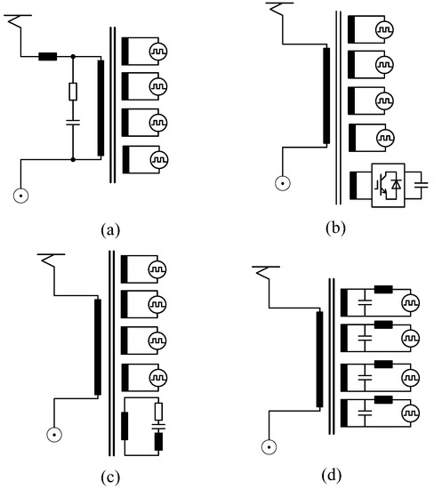
Figure 1.
Harmonics compensation methods for AC locomotives: (a) passive harmonic filter (compensation on the high-voltage side), (b) active harmonic compensator, (c) passive harmonic filter (compensation with additional filter windings), and (d) LCL-type filter compensation on the low-voltage side.
Although the LCL-type filter scheme can effectively suppress the high-frequency harmonics, additional harmonic filters should be installed in high-speed trains. Due to the limited space in high-speed trains for stacking air-core inductors, the space required for LCL-type filter devices needs to be reduced. To this end, the magnetic integration technique is an effective solution. A magnetic integration theory is introduced in [13,14], in which the two inductors of LCL-type filters are integrated into an EE-type (which means the shape of the iron core is like the character E) core structure. The weak coupling effect observed in those inductors will impose a negative impact on the performance of the LCL-type filter. To address this problem, the coupling coefficient can be utilized to form an inductive-inductive-capacitive-inductive (LLCL)-type filter to suppress the most predominant harmonic currents [15]. In [16], an active magnetic decoupling method is proposed by winding a decoupling winding in series with the filter capacitor around the common I-type core. Therefore, the harmonic attenuation capability can be realized and the volume of the filtering device can be reduced to a large extent. In [17], the grid side inductor of an LCL-type filter is integrated with the leakage inductance of the transformer, but the authors do not investigate the integration of the converter-side inductor of the LCL-type filter.
Although these existing magnetic integration methods can reduce the coverage space of LCL-type filter equipment, they may not be suitable for use in traction drive systems. To address this issue, this paper proposes a harmonic suppression traction transformer (HSTT) with integrated filtering inductors (IFIs) [18] for high-speed trains. Based on this, an innovative magnetic integrated LCL-type filter can satisfy the power quality requirements, while being well-suited for limited space available on locomotives. Each IFI winding is composed of two series-connected sub-windings with the same turns and opposite directions. Similar structures have been applied to a distribution transformer [19], rectifier transformer [20], and inductive filtering transformer [21,22]. The proposed IFI method has the merits of a simple inductance design, good linearity of inductance, low impact on transformer operation, and ease of manufacture and application.
The contributions of this paper are listed as follows:
- An HSTT with integrated filtering inductors is proposed;
- The principle of magnetic decoupling of the IFIs is analyzed;
- The design process of the HSTT with IFIs is specifically introduced;
- The proposed method is verified in terms of volume reduction and harmonic suppression effect.
The remainder of this paper is organized as follows. The topology structure of the grid-side traction converter with an LCL-type filter is described in Section 2, along with the magnetic analysis of the proposed HSTT with IFIs. Moreover, a step-by-step calculation and design guidance of the HSTT with IFIs is introduced in Section 3. In Section 4, the simulations and experiments are performed to verify the effectiveness of the proposed concepts. Finally, Section 5 draws a conclusion.
2. Description and Magnetic Analysis of the HSTT with IFIs
2.1. Descriptions of the Traction Drive System with IFI-Based LCL-Type Filter
Figure 2 shows the proposed circuit topology of an IFI-based, single-phase LCL-type converter unit. An LCL-type filter is composed of the leakage inductance (Lg) of the traction transformer, an added filter capacitor (Cf), and an IFI (Lf). Cd is the DC-link capacitor; RL is the equivalent resistor of a load from the traction drive system; vg is the voltage of the traction grid, ig and if are the grid-side current and converter-side current, respectively; is is the secondary current of the traction transformer; vc and ic are the voltage and current of the filter capacitors, respectively. Here, uab is the input voltage of converter, and udc and idc represent the DC-side voltage and current, respectively.
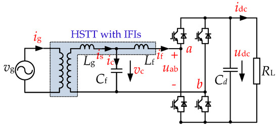
Figure 2.
Diagram of single-phase grid-side converters with an LCL-type filter.
Figure 3 depicts the structure of the HSTT with IFIs. The proposed HSTT is a single-phase transformer with split multiwindings, where the iron core adopts the “C-core” core type with two core limbs. On each core limb, two coils of the high-voltage (HV) winding and two split windings of the low-voltage (LV) winding are concentrically wound. The HV windings are connected in parallel, and the LV windings operate independently. Designed for insulation, the HV winding is generally arranged outside of the LV winding. Moreover, compared with the conventional traction transformer, the proposed HSTT adds two additional sub-windings in each unit to constitute an IFI, which is arranged inside the LV windings.
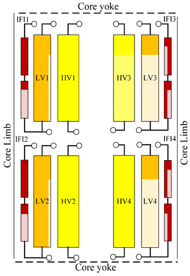
Figure 3.
Structure of the harmonic suppression traction transformer (HSTT) with integrated filtering inductors (IFIs).
2.2. Magnetic Analysis of the IFI Windings
Figure 4a shows the schematic diagrams of the IFI windings. For instance, IFI 1 windings are composed of two series-connected sub-windings, a and b, which are sub-windings wound around the same magnetic core with the same turns and structural dimensions. Moreover, each sub-winding convolves in the opposite direction. Figure 4b shows the magnetic field distribution of the IFI 1 windings. The magnetic flux generated by the energized IFI winding 1 can be divided into the main magnetic flux and leakage magnetic flux; the former passes completely through the magnetic core, and the latter passes through the oil or air. The main magnetic flux () and the leakage magnetic flux () of IFI 1 windings can be derived as
where and represent the main magnetic flux generated by the sub-winding a and sub-windings b, respectively; and represent their leakage magnetic fluxes, respectively.
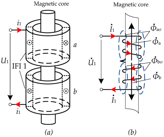
Figure 4.
Schematic diagram of IFI windings: (a) winding structure diagram; (b) magnetic flux distribution diagram.
Referring to Figure 4b, the expressions of the main magnetic flux can be described as
where (k = a, b) represents the magnetomotive force of the sub-winding k, Nk is the number of turns of the sub-winding k; is the current flowing through the sub-winding k; Rk = l/(μAc) represents the magnetic resistance of the magnetic path of the sub-winding k in the core, where l is the magnetic path length, Ac is the cross-sectional area, and μ is the core permeability.
Because the two sub-windings are wound on the same core with the same turns, it can be deduced that Ra = Rb = R and Na = Nb = N′. Moreover, as the current flows through the two sub-windings in opposite directions, the following equation can be obtained as
Then, the expression of the leakage flux can be given by
where Rkσ represents the magnetic resistance of the magnetic path of the sub-winding k in oil or air.
The leakage magnetic fields of the two sub-windings are established in different spatial regions, thus, we have Raσ ≠ Rbσ. Substituting Equations (3) and (4) into (1) yields
Equation (5) clearly illustrates that because the main magnetic fluxes generated by the two sub-windings are opposite in direction and have the same amplitude, therefore, the total main magnetic flux of IFI winding 1 in the core is zero. That is to say, the magnetic flux of IFI winding 1 depends on the leakage magnetic flux of the two sub-windings. Thus, the inductance value of each IFI winding can be calculated by the magnetic field energy method.
2.3. Magnetic Analysis of the HSTT with IFIs
Figure 5 depicts a transformer winding T, iron core, and two IFI windings. The transformer windings T represents the HV or LV windings of the HSTT. IFI windings 1 and 2 are averaged and divided into sub-windings a and b, and sub-windings c and d, respectively. Here, sub-windings a and b, as well as sub-windings c and d, are of a symmetrical mirror relationship to winding T. As already mentioned, the main magnetic flux in the iron core generated by IFI windings 1 and 2 is zero. This means the main magnetic flux decoupling between the IFI windings and other windings can be realized.
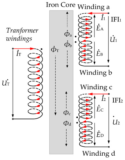
Figure 5.
Diagrams of the transformer windings and IFI windings of the HSTT.
Due to the mirror symmetry arrangement of sub-windings a and b to winding T, the equations of the mutual inductance between winding T and the two sub-windings a and b can be obtained as
The current in winding T is denoted as IT, by which the mutual flux linkage in sub-windings a and b are motivated, and thus expressed as ψq-T = Ma-TIT and ψb-T = Mb-TIT, respectively. Thus, the induction electromotive forces (EMF) of the sub-windings a and b can be expressed as
As a result, the composite EMF in the winding 1 induced by winding T can be obtained as
Similarly, it can be concluded that the EMF of winding T generated by the current in IFI winding 2 is also approximately equal to 0. Consequently, the power decoupling between the IFI winding and the transformer windings can be realized.
The EMF in winding 1 induced by winding 2 can be expressed as
The mutual inductance of the windings of the integrated inductor can be achieved as below
By substituting Equation (10) into (9), we have E1–2 ≈ 0. A similar conclusion can be drawn that the EMF E2–1 is approximately equal to zero. Thus, the magnetic decoupling of IFI windings with transformer windings and other IFI windings can be realized.
It can be concluded that based on the proposed inductor integration method, the IFIs can be obtained with the linearity inductance. Moreover, the IFIs can operate independently with other windings of the traction transformer.
3. Math Design and Calculations Methods of the HSTT with IFIs
3.1. LCL-Type Filter Design
To ensure the harmonics suppression effect and steady operation of the LCL-type converter system, the parameters of the LCL-type filter should be specifically designed [23,24,25,26,27,28].
Generally, the reactive power, which is supported by the capacitor, should not exceed 5% of the rated power of the system. Hence, the capacitor of the LCL-type filter can be derived as
where Pn is the rated power of the system, and fn is the fundamental frequency of the traction grid.
The inductance of the converter side is determined by the modulation method and the permissible maximum current fluctuation. As the unipolar modulation is applied for the traction converter [29] and the current restrictions of the converter side current are set in the range of 30–40% of the rated current [12], the inductance of the converter side inductor can be obtained with
where fs represents the switching frequency of the converter and Δimax is the permissible maximum converter side current fluctuation.
The ratio of the grid-side high-order harmonic current to converter-side high-order harmonic current can be derived as
where ωk is the double switching angular frequency and k is the order of the harmonic current.
As an appropriate attenuation coefficient of N should be chosen to suppress the high-frequency harmonics in the grid-side current, the inductance of Lg can be calculated as
The resonant frequency of the LCL-type filter yields
To guarantee the stability of the entire system, the resonant frequency of the LCL-type filter must be set within a reasonable range. In this paper, it should be limited in the following range
3.2. Dimension-Based Method
Based on the designed parameters of the two inductors of the LCL-type filter, Figure 5 shows the dimension-based method (DBM) [18,19], which is devoted to designing the practical structure parameters of proposed HSTT with IFIs.
As shown in Figure 2, the LCL-type filter consists of Lg and Lf, where Lg is the leakage inductance of the traction transformer. Figure 6 shows the dimension of the HSTT with IFIs, where the turns of the HV winding of the traction transformer is set as N1. Lf consists of sub-windings W1 and W2, and the turns are both equal to N2. According to the dimension-based method, the inductance of the LCL-type filter can be determined by
where , and
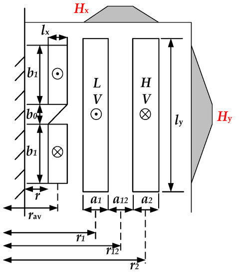
Figure 6.
The dimensions of the HSTT with IFIs.
3.3. Inductance Matrix Based Calculation
The structural parameters of the HSTT with IFIs can be achieved via the DBM. On this basis, the inductance matrix-based calculation (IMBC) methods are used to verify the coupling effect of the inductors. The IMBC methods include the reduced-order inductance matrix method (ROIMM) [19] and the short-circuit impedance matrix method [30]. Based on the inductance matrix of the windings of the HSTT with IFIs, which are calculated by the finite-element simulations method, the leakage inductances of the traction transformer and inductances of the IFIs can be obtained with IMBC methods.
The coupling coefficient matrix of the HSTT with IFIs can be calculated by
where Lp and Lq represent the self-inductance of each winding, and Mpq represents the mutual inductance of windings p and q.
Figure 7 shows the flowchart of the design and calculation procedure of the proposed HSTT with IFIs. Starting with some selected initial values (Pn, Vg, fn, Udc, fs, Δimax, N), the LCL-type filter parameters can be obtained by Equations (11), (12), and (14). Then, it is confirmed whether the resonant frequency of the LCL-type filter meets the limitations given by Equation (16) or not. Therefore, the qualified LCL-type filter parameters can be acquired. Subsequently, with the reference value of the two inductors of Lg and Lf, the basic structural parameters of the proposed HSTT with IFIs can be obtained via Equations (19) and (20). Then, the finite element model of the HSTT with IFIs can be built with its structural parameters, so the inductance matrix of the HSTT with IFI windings can be calculated. The inductance of the HSTT and IFIs can be obtained by the IMBC methods afterward. The design and calculation procedure of the HSTT with IFIs ends if the calculated inductances meet the designed error (ε).
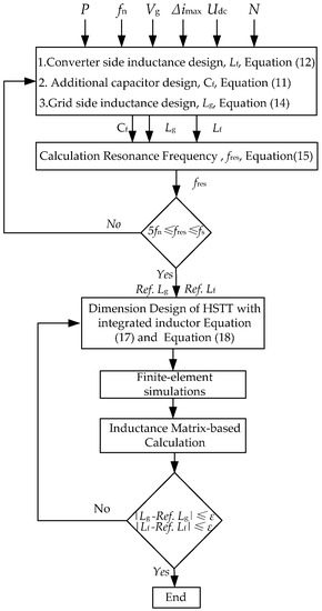
Figure 7.
Flowchart of design and calculation procedure of the proposed HSTT with IFIs.
4. Simulation and Experiment Results
4.1. Control Method
In order to ensure the stability of the entire system, the main challenge here is to suppress the resonance caused by the LCL-type filter. There are usually two solutions, namely the passive damping method and the active damping method. Since the passive damping method inevitably leads to more loss compared to the active damping method, the active damping method seems more attractive for high-power applications. The active damping can be realized by the feedback of different state variables [31]. Figure 8 shows the capacitive current-based feedback control method [32]. This damping method is adopted in this paper because of its simple realization. Here, vg is the voltage of the traction grid, ig and if are the grid-side current and converter-side current, respectively; vc and ic are the voltage and current of the filter capacitors, respectively; vcov and vr are the input voltage and reference input voltage of the converter, respectively. Kpwm denotes the equivalent gain of PWM converter.
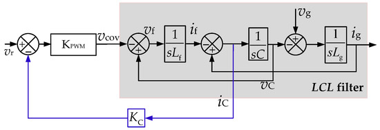
Figure 8.
Block diagram of voltage source converter (VSC) with an LCL-type filter.
4.2. Field-Circuit Coupling Simulation
Figure 9 shows the implementations of the field-circuit coupling simulation of the traction drive system with an HSTT, which is built in ANSYS/Maxwell and ANSYS/Simplorer to verify the correctness of the proposed magnetic integration method. The simulation parameters are shown in Table 1.
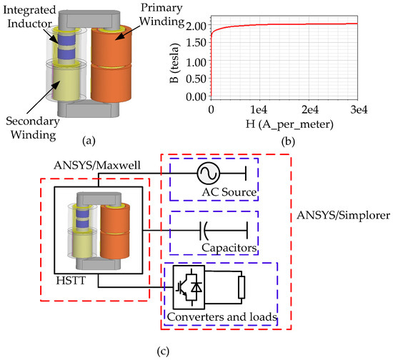
Figure 9.
Field-circuit coupling simulations for the (a) 3D finite-element model of the HSTT, (b) B-H curve of the transformer core, and (c) model diagram.

Table 1.
Parameters of the HSTT with IFIs and traction drive system for simulation.
According to the dimension-based method, the physical structure parameters of the HSTT with IFIs can be deduced. Figure 9a shows the three-dimensional (3D) model of the HSTT with the IFIs, which is established in ANSYS/Maxwell. Figure 9b depicts the magnetization (B-H) curve of the 30Q130 silicon steel from which the transformer core is made. Figure 9c shows the model built in the ANSYS/Simplorer.
The self- and mutual-inductance matrices covering all windings in the transformer can be calculated in the ANSYS/Maxwell simulation environment. Then, according to the ROIMM [21], the inductance matrix of the 12-order matrix, represented as M12, can be obtained, as shown in the Appendix A. According to Equation (21), the coupling factors matrix K12 can be obtained. The inductances of the HSTT with IFIs can be calculated with IMBC methods, and the specifications of Lg and Lf are presented in Table 2. Compared with the designed values of the inductances in Table 1, the error between simulation value and the designed value of the inductances is below 5 %. Thus, the inductance is in good accordance with the design requirements. Moreover, as the coupling factor of IFI windings with transformer windings is below 1 %, the high-decoupling characteristics of IFI windings demonstrated in Section 2 can be verified.
Table 2.
Simulated inductances of the HSTT with IFIs.
To further prove the harmonics suppression effect of the IFI-based LCL-type scheme, simulation comparisons of filtering performance of the IFI-based L-type filter, IFI-based LCL-type filter, and discrete inductor-based LCL-type filter are performed in this section. It is worth noting that the external circuit is added to the finite element model in ANSYS/Simplorer, so as to develop the field-circuit coupling simulations. Particularly, the external electric circuit model mainly contains an AC source with 25 kV rated voltage, line-side traction converters with equivalent load, and the control part of the system.
Figure 10 shows the simulation results of secondary-side current (is1) of the HSTT with two different filter types. Figure 11 shows the comparison of the harmonic spectra of the secondary-side current in three cases. It can be inferred from Figure 10 and Figure 11 that IFI-based L-type filter schemes and LCL-type filter schemes can both operate stably. Moreover, the IFI-based LCL-type filter schemes can better suppress high-frequency harmonics. Besides, the same level of harmonic suppression effect can be obtained as with the discrete inductor-based LCL-type filter scheme.
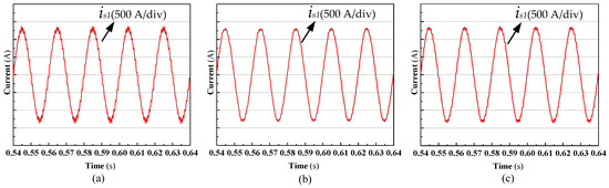
Figure 10.
Simulated waveforms of secondary-side current (is1): (a) IFI-based L-type filter; (b) discrete inductor-based LCL-type filter; (c) IFI-based LCL-type filter.
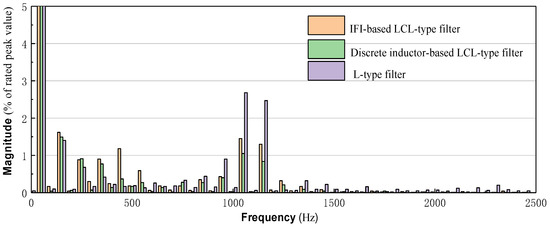
Figure 11.
Comparison of simulated fast Fourier transform (FFT) analysis result of secondary-side current (is1).
Figure 12 shows the waveforms of the grid-side voltages (vg) and grid-side currents (ig) of the HSTT with four secondary windings. It is clear that the grid-side currents of all the cases can operate in phases with the grid-side voltage, and they are highly sinusoidal. Figure 13 shows the comparative results of the harmonic spectra of the grid-side current for the above-mentioned three cases. The harmonic spectrum of the grid-side currents with the L-type filter scheme distributes around 4400 Hz due to the phase shift control, but the IFI-based and discrete inductor-based LCL-type filter schemes can dampen these high-frequency harmonic currents on the train side to almost the same level. Therefore, the effectiveness of the IFI-based LCL-type filter scheme for high-frequency harmonics suppression can be confirmed.
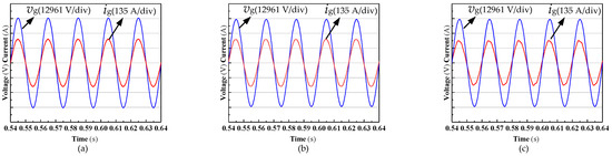
Figure 12.
Simulated waveforms of grid voltage (vg) and grid current (ig) for: (a) IFI-based L-type filter; (b) discrete inductor-based LCL-type filter; and (c) IFI-based LCL-type filter.
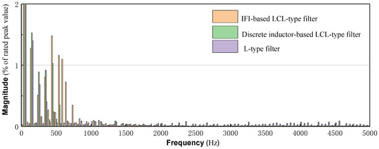
Figure 13.
Comparison of the simulated FFT analysis result of ig.
4.3. Practical Operations
A 10 kVA prototype of the HSTT with two IFIs and its experiment platform is established. The parameters of the prototype and experimental platform are listed in Table 3.
Table 3.
Parameters of the HSTT and converter system.
Table 4 shows the results of the designed, calculated, simulated, and measured inductance of the HSTT with IFIs. The errors of the two IFIs are within the allowed range. Thus, the validity of the design method is proven. Furthermore, the measured coupling factors of the integrated inductors with traction windings are shown in Equation (22), where h1, l1, and i1 represent the high-voltage windings, low-voltage windings, and IFI windings, respectively, and the same for {h2, l2, i2}. From Equation (22), it can be seen that the values of coupling factors between IFIs and transformer windings are below 0.01, which verifies the decoupling performance of the proposed method.
Table 4.
Inductances obtained by different methods.
Figure 14 compares the coverage area of the HSTT with IFIs to that with discrete inductors. It can be seen that the HSTT with IFIs (10 kVA) needs a coverage area of 0.051 m2. In order to avoid the electromagnetic interference between equipment, the regular HSTT (10 kVA) with a configuration of separated hollow inductors covers an area of 0.083 m2. This indicates that the total installed area of equipment can be reduced by 38.5% when IFIs are adopted. Furthermore, in practical application, the inductance of the IFIs and capacity of the transformer is usually much larger, which will result in a smaller installed area. As a result, a high power density LCL-type filter system is implemented.
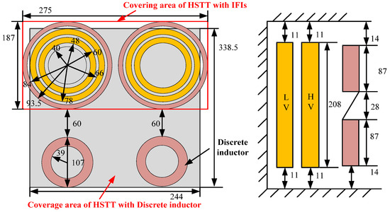
Figure 14.
Comparison between the covering area of the HSTT with IFIs and that of discrete inductors (units = mm).
Figure 15 shows the experimental platform, which is used to verify the high-frequency harmonics suppression effect with the proposed method. The DSP-TMS320F28335 (Texas Instruments, Dallas, USA) is used to sample signals and implement the control algorithm in this platform, and an oscilloscope is used to display the voltage and current waveforms.
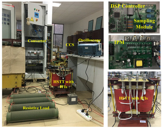
Figure 15.
Photography of the experimental system.
Figure 16 shows the experimental results when the prototype of the HSTT with IFIs is adopted as an LCL-type filter, while Figure 17 shows the experimental results of LCL-type filtered single-phase converter, which is composed of the HSTT combined with discrete inductors. Clearly, both systems can operate stably, and the waveform of the grid-side current is nearly sinusoidal and in phase with the grid voltage. Furthermore, from those figures, the current ripple of double the switching frequency is damped to almost the same level, which is also within the allowed range. Therefore, the effectiveness of the proposed scheme for high-frequency suppression can be validated.
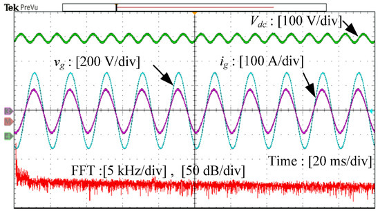
Figure 16.
Experimental results of the HSTT with an IFI-based LCL-type filtered single-phase converter.
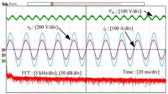
Figure 17.
Experimental results of the HSTT with a discrete inductor-based LCL-type filtered single-phase converter.
5. Conclusions
In this paper, a scheme for a single-phase LCL-type converter is adopted in the traction drive system for high-frequency harmonics suppression. Considering that the space in high-speed trains is extremely limited, an innovative HSTT with IFIs is proposed. The IFI has an effective magnetic decoupling structure, and the installation space of the filter device can be greatly reduced. Simulation and experimental results show that the proposed IFI-based LCL-type filter scheme can achieve similar harmonic attenuation performance as the discrete LCL-type filter scheme. The IFI method can also be applied to other engineering practices.
Author Contributions
All the authors made contributions to the concept and design of the article. Y.L. (Yuxing Liu) is the main author of this work. J.X. provided good advice and technical guidance for the manuscript. Z.S., Y.L. (Yong Li), Y.P., C.L., G.C., S.H., M.Z., and B.X. reviewed and improved the manuscript. All authors have read and agreed to the published version of the manuscript.
Acknowledgments
This work was supported by the National Natural Science Foundation of China (NSFC) under grant 51477044 and 51707060, and by the Excellent Youth Project of Hunan Provincial Department of Education under grant 18B223.
Conflicts of Interest
The authors declare no conflict of interest.
Appendix A
By means of the calculation of the 3D finite element model, the inductance matrix M12 and corresponding coupling efficiency matrix K12 covering all windings of the prototype of the transformer integrated with the integrated inductor as below (unit = mH). Here, h1, l1, and i1 represent the high-voltage windings, low-voltage windings, and IFI windings, respectively; the same is true for {h2, l2, i2}, {h3, l3, i3}, and {h4, l4, i4}.
References
- Hu, H.; Shao, Y.; Tang, L.; Ma, J.; He, Z.; Gao, S. Overview of harmonic and resonance in railway electrification systems. IEEE Trans. Ind. Appl. 2018, 5, 5227–5245. [Google Scholar] [CrossRef]
- He, Z.; Hu, H.; Zhang, Y.; Gao, S. Harmonic resonance assessment to traction power-supply system considering train model in China high-speed railway. IEEE Trans. Power Del. 2013, 4, 1735–1743. [Google Scholar] [CrossRef]
- Liu, J.; Yang, Q.; Zheng, T.Q. Harmonic analysis of traction networks based on the CRH380 series EMUs accident. In Proceedings of the IEEE Transportation Electrification Conference and Expo (ITEC), Dearborn, MI, USA, 18–20 June 2012. [Google Scholar]
- Hu, H.; He, Z.; Gao, S. Passive filter design for China high-speed railway with considering harmonic resonance and characteristic harmonics. IEEE Trans. Power Del. 2014, 30, 505–514. [Google Scholar] [CrossRef]
- Tan, P.-C.; Loh, P.C.; Holmes, D.G. A robust multilevel hybrid compensation system for 25-kV electrified railway applications. IEEE Trans. Power Electron. 2004, 4, 1043–1052. [Google Scholar] [CrossRef]
- Holtz, J.; Krah, J. Adaptive optimal pulse-width modulation for the line-side converter of electric locomotives. IEEE Trans. Power Electron. 1992, 1, 205–211. [Google Scholar] [CrossRef]
- Zhang, R.; Lin, F.; Yang, Z.; Cao, H.; Liu, Y. A harmonic resonance suppression strategy for a high-speed railway traction power supply system with a SHE-PWM four-quadrant converter based on active-set secondary optimization. Energies 2017, 10, 1567. [Google Scholar] [CrossRef]
- Cui, H.; Song, W.; Fang, H.; Ge, X.; Feng, X. Resonant harmonic elimination pulse width modulation-based high-frequency resonance suppression of high-speed railways. IET Power Electron. 2015, 5, 735–742. [Google Scholar] [CrossRef]
- Song, K.; Konstantinou, G.; Mingli, W.; Acuna, P.; Aguilera, R.P.; Agelidis, V.G. Windowed SHE-PWM of interleaved four-quadrant converters for resonance suppression in traction power supply systems. IEEE Trans. Power Electron. 2016, 10, 7870–7881. [Google Scholar] [CrossRef]
- Krah, J.-O.; Holtz, J. Total compensation of line-side switching harmonics in converter-fed AC locomotives. IEEE Trans. Ind. Appl. 1995, 6, 1264–1273. [Google Scholar] [CrossRef]
- Aceiton, R.; Weber, J.; Bernet, S. Input filter for a power electronics transformer in a railway traction application. IEEE Trans. Ind. Electron. 2018, 12, 9449–9458. [Google Scholar] [CrossRef]
- Song, W.; Jiao, S.; Li, Y.W.; Wang, J.; Huang, J. High-frequency harmonic resonance suppression in high-speed railway through single-phase traction converter with LCL filter. IEEE Trans. Transport. Electrif. 2016, 3, 347–356. [Google Scholar] [CrossRef]
- Lee, K.-J.; Park, N.-J.; Kim, R.-Y.; Ha, D.-H.; Hyun, D.-S. Design of an LCL filter employing a symmetric geometry and its control in grid-connected inverter applications. In Proceedings of the IEEE Power Electronics Specialists Conference, Rhodes, Greece, 15–19 June 2008. [Google Scholar]
- Pan, D.; Ruan, X.; Bao, C.; Li, W.; Wang, X. Magnetic integration of the LCL filter in grid-connected inverters. IEEE Trans. Power Electron. 2013, 4, 1573–1578. [Google Scholar] [CrossRef]
- Fang, J.; Li, H.; Tang, Y. A magnetic integrated LLCL filter for grid-connected voltage-source converters. IEEE Trans. Power Electron. 2016, 3, 1725–1730. [Google Scholar] [CrossRef]
- Li, X.; Fang, J.; Lin, P.; Tang, Y. Active magnetic decoupling for improving the performance of integrated LCL-filters in grid-connected converters. IEEE Trans. Ind. Electron. 2017, 2, 1367–1376. [Google Scholar] [CrossRef]
- Pleite, J.; Valdivia, V.; Zumel, P.; Gonzalez, C. Transformer and Series Inductance Integration for Harmonic Filtering in PWM Inverters Based in a Simple Design Procedure. In Proceedings of the IEEE International Symposium on Industrial Electronics, Vigo, Spain, 4–7 June 2007. [Google Scholar]
- Liang, C.; Luo, L.; Li, Y.; Xu, J.; Qi, Q.; Chen, Y.; Zhou, G.; Deng, M. An integrated harmonic-filtering transformer for low-voltage distribution systems. IEEE Trans. Magn. 2015, 11, 1–4. [Google Scholar]
- Xu, J.; Gu, X.; Liang, C.; Bai, Z.; Kubis, A. Harmonic suppression analysis of a harmonic filtering distribution transformer with integrated inductors based on field–circuit coupling simulation. IET Gener. Trans. Distrib. 2017, 3, 615–623. [Google Scholar] [CrossRef]
- Li, Y.; Peng, Y.; Liu, F.; Sidorov, D.; Panasetsky, D.; Liang, C.; Luo, L.; Cao, Y. A controllably inductive filtering method with transformer-integrated linear reactor for power quality improvement of shipboard power system. IEEE Trans. Power Del. 2016, 4, 1817–1827. [Google Scholar] [CrossRef]
- Zhang, M.; Li, Y.; Liu, F.; Li, W.; Peng, Y.; Wu, W.; Cao, Y. Cooperative Operation of DG Inverters and a RIHAF for Power Quality Improvement in an Integrated Transformer-Structured Grid-Connected Microgrid. IEEE Trans. Ind. Appl. 2018, 2, 1157–1170. [Google Scholar] [CrossRef]
- Liu, Q.; Li, Y.; Luo, L.; Peng, Y.; Cao, Y. Power quality management of PV power plant with transformer integrated filtering method. IEEE Trans. Power Del. 2018, 3, 941–949. [Google Scholar] [CrossRef]
- Liu, Q.; Peng, L.; Kang, Y.; Tang, S.; Wu, D.; Qi, Y. A novel design and optimization method of an LCL filter for a shunt active power filter. IEEE Trans. Ind. Electron. 2013, 8, 4000–4010. [Google Scholar] [CrossRef]
- Jalili, K.; Bernet, S. Design of LCL filters of active-front-end two-level voltage-source converters. IEEE Trans. Ind. Electron. 2009, 5, 1674–1689. [Google Scholar] [CrossRef]
- Liserre, M.; Blaabjerg, F.; Hansen, S. Design and control of an LCL-filter-based three-phase active rectifier. IEEE Trans. Ind. Appl. 2005, 5, 1281–1291. [Google Scholar] [CrossRef]
- Tang, Y.; Loh, P.C.; Wang, P.; Choo, F.H.; Gao, F.; Blaabjerg, F. Generalized design of high performance shunt active power filter with output LCL filter. IEEE Trans. Ind. Electron. 2011, 3, 1443–1452. [Google Scholar] [CrossRef]
- Bao, C.; Ruan, X.; Wang, X.; Li, W.; Pan, D.; Weng, K. Step-by-step controller design for LCL-type grid-connected inverter with capacitor–current-feedback active-damping. IEEE Trans. Power Electron. 2013, 3, 1239–1253. [Google Scholar]
- Said-Romdhane, M.; Naouar, M.; Belkhodja, I.; Monmasson, E. An improved LCL filter design in order to ensure stability without damping and despite large grid impedance variations. Energies 2017, 10, 336. [Google Scholar] [CrossRef]
- Chang, G.W.; Lin, H.-W.; Chen, S.-K. Modeling characteristics of harmonic currents generated by high-speed railway traction drive converters. IEEE Trans. Power Del. 2004, 2, 766–773. [Google Scholar] [CrossRef]
- Xie, B.; Li, X.; Chen, Q.; Zhang, Y.; Wang, J. Calculation of the circulating current and short- circuit impedance of a 3000kVA HTS transformer with split types of windings. In Proceedings of the International Conference on Electrical Machines and Systems (ICEMS), Seoul, Korea, 8–11 October 2007. [Google Scholar]
- Yoon, S.-J.; Lai, N.; Kim, K.-H. A systematic controller design for a grid-connected inverter with LCL filter using a discrete-time integral state feedback control and state observer. Energies 2018, 11, 437. [Google Scholar] [CrossRef]
- Lorzadeh, I.; Askarian Abyaneh, H.; Savaghebi, M.; Bakhshai, A.; Guerrero, J.M. Capacitor current feedback-based active resonance damping strategies for digitally-controlled inductive-capacitive-inductive-filtered grid-connected inverters. Energies 2016, 9, 642. [Google Scholar] [CrossRef]


© 2020 by the authors. Licensee MDPI, Basel, Switzerland. This article is an open access article distributed under the terms and conditions of the Creative Commons Attribution (CC BY) license (http://creativecommons.org/licenses/by/4.0/).