Abstract
In this study, CO2 and SO2 captures from post-combustion flue gas from a pulverized coal-fired power plant were evaluated using deep eutectic solvents (DES) to replace existing mono-ethanol amine (MEA) and CanSolv technologies. The system design of the DES-based CO2 and SO2 capture was based on the National Energy Technology Laboratory’s (NETL) 550 MWe pulverized coal-fired power plant model using Illinois #06 coal. Two of the most studied DES (choline chloride and urea at a 1:2 molar ratio and methyltriphenylphosphonium bromide (METPB) and ethylene glycol at a 1:3 molar ratio) for CO2 and SO2 capture were evaluated for this system analysis. Physical properties of DES were evaluated using both density functional theory (DFT)-based modeling as well as with documented properties from the literature. A technoeconomic assessment (TEA) was completed to assess DES ability to capture CO2 and SO2. Both solvents were able to fully dissolve and capture all SO2 present in the flue gas. It was also found from the system analyses that choline chloride and urea outperformed METPB and ethylene glycol (had a lower final cost) when assessed at 10–30% CO2 capture at high operating pressures (greater than 10 bar). At high system sizes (flow rate of greater than 50,000 kmoles DES per hour), choline chloride:urea was more cost effective than METPB:ethylene glycol. This study also establishes a modeling framework to evaluate future DES for physical absorption systems by both thermophysical and economic objectives. This framework can be used to greatly expedite DES candidate screening in future studies.
1. Introduction
Carbon capture from post combustion coal-fired power plants and processing facilities will be vital in reducing the amount of greenhouse gases emitted by the energy sector in the U.S. State-of-the-art carbon dioxide (CO2) capture technologies have been primarily focused around amine-based solvents, which accounts for more than 30% capital costs at 700 Million USD (2011) for a 550 MWe power plants [1,2]. This additional cost for carbon capture reduces power plant overall efficiency from 39.0% to 31.2% [1,2]. Moreover, monoethanolamine (MEA), as well as other amine-based solvents, can degrade from a variety of contaminants found in gas, such as SOx or NOx, or through thermal degradation [3,4]. Furthermore, unfavorable side reactions can occur that severely reduce the selectivity of the solvent by causing precipitation or forming inert species that reduce the overall effectiveness of the carbon capture process [5]. The replacement of the amine-based solvents can account for an additional 10% increase of CO2 capture cost [1,2,6]. Moving to a physical absorption process with a solvent that does not react with the common oxygenated species (oxygen, CO2, SOx, etc.) found in flue gas can greatly reduce the cost of carbon capture from both power plants and other industrial processes that produce CO2.
Deep eutectic solvents (DES) are a class of unique solvents comprised with hydrogen bond donors (HBD) and hydrogen bond acceptors (HBA), which minimizes melting points as well as influence other physical and chemical properties of individual substances [7]. Various DES including choline chloride and urea (ChCl:Urea at a 1:2 molar ratio) and methyltriphenylphosphonium bromide and ethylene glycol (METPB:EG at a 1:3 molar ratio) have been reported to be effective for CO2 capture [7,8,9,10,11]. At pressures below 10 bar, ChCl-based DES have been shown to dissolve CO2 at proportions of up to 0.3 moles CO2 per kg of solvent via physical absorption [12]. Chen et al. demonstrated that even simple DES pairs made of dihydric butanols and propanols are able to dissolve 0.14–0.18 moles of CO2 per kg of solvent at 5 atm of pressure [10]. Even a full-scale evaluation of DES has recently been completed on the upgrading of biogas and a review of CO2 removal from gas [13,14]. Chunya et al. found that certain DES can outperform dimethyl ether of polyethylene glycol for biogas upgrading, but that the system was highly sensitive to the viscosity of the selected solvent [13]. Other DES, as well as ionic liquids, have also been shown to capture SO2 at an even lower pressures with higher selectivities than CO2 [15,16,17]. In the case of flue gas remediation, separate processes are used to remove SO2 (FGD unit) and CO2 (carbon capture unit), where a DES-based solvent process could remove both gases in a single process. Though these various studies show promising results in regard to utilizing DES as a more efficient solvent, they are not able to be applied outside of the specific DES that were studied. The field of deep eutectics is both promising and difficult as there are nearly infinite combinations of HBAs and HBDs that can synergistically interact. More advanced screening and evaluations tools must be established, else efforts and resources will be spent fruitlessly on investigating solvents that could be ruled out as ineffective early on in a study.
To the authors’ knowledge, no study on the economic viability of DES for SO2-CO2 capture in a powerplant has been reported. Therefore, basic conclusions on a DES absorption system viability or more complex points such as system sensitivity to thermophysical parameters cannot be made. Furthermore, as the discovery and documentation of DES continues, it is necessary to set thresholds that must be met to achieve an economically feasible process using DES. This study aims to both evaluate currently known and documented DES for SO2-CO2 capture from a 550 MWe powerplant as well as establish the required thermophysical properties thresholds that must be met to consider a DES for further evaluation as a SO2-CO2 solvent. Choline chloride and urea at a 1:2 molar ratio and METPB and ethylene glycol at a 1:3 molar ratio were considered as the baseline solvents for evaluating this study. Both solvent combinations have been studied extensively and have relatively well documents thermophysical properties [8,18]. This study seeks to establish the basis for evaluating DES in physical absorption processes through both fundamental equations as well as an economic analysis framework. Both of these components will be useful for preliminary screening of future DES, as manual evaluation without some sort of framework would be extremely tedious and wasteful.
2. Materials and Methods
2.1. Characteristics of Flue Gas and Baseline Process
The properties inlet flue gas stream for this process was adopted from a model evaluation of power plants performed by the National Energy Technology Laboratory (NETL) in order to compare the DES-based absorption system with the current technology [2]. This evaluation included a technoeconomic assessment of various power plant configurations, and case study B11B (550 MWe, pulverized coal, subcritical powerplant with carbon capture) serves as the baseline for this study [2]. The flue gas stream has a mass flow rate of 2,687,126 kg/hr, with a mass composition of 0.88% argon, 13.76% CO2, 8.31% water, 73.45% N2, 3.4% O2, and 0.2% SO2. SO2 is removed via a wet flue gas desulphurization (FGD) process using a calcium spray that forms gypsum. The SO2 deficient gas is then sent to a carbon removal unit. The carbon rich flue gas a dual-stage absorption-stripper system that uses chemical absorption (MEA-based) to remove the CO2. Overall the baseline system removes more than 99.9% of SO2 and approximately 90% of the CO2. The flue gas stream that enters this eutectic solvation process is taken before either of the flue gas treatment processes, and as such enters at 143 °C and atmospheric pressure.
2.2. Modeling of Deep Eutectic Solvents
Thermophysical properties of DES are not always readily available yet required for the system analysis. Molecular modeling using various software that utilize density functional theory (DFT) can be used in substitution of experiments to estimate these properties. A density function theory (DFT)-based molecular modelling software, CosmoTherm, was used in this study to model DES and estimate thermophysical properties for the DES. CosmoTherm’s TmoleX module was used to create COSMO profiles for DES components. The choline cation as well as the methyltriphenylphosphonium cation were modeled using the Tri-Zeta Valence Polarizable (TZVP) parameters. COSMO profiles of DES are the energetically favorable configuration of the components. TZVP parameter set was selected as it is more flexible and precise when considering electrostatic interactions between molecules. By using the COSMO parameter selection along with the TZVP parameter set, the modeled DES molecules are considered as ideal conductors. On the other hand, chloride, bromide, urea, CO2, and SO2 molecules were used from COSMO’s existing TZVP library. This allows the DES components to capture the correct electronic nature that reflects DESs’ macroscopic behavior such as gas absorption. COSMOThermx18’s gas solubility option was used for determining Henry’s law constants [19,20]. Modeled parameters, as well as other parameters taken from the literature, are shown in Table 1. Though all properties in Table 1 were modeled for this study, those found in the literature supported by experimental data were used preferably when available, with modeled parameters filling in gaps between or beyond the reported experimental conditions [18,21,22].

Table 1.
DES Solvent Properties from the Literature and COSMO.
2.3. Process Model for CO2 Absorption
Dual-Stage DES-Based Absorption System
Both DES selected for this study readily dissolve SO2 more selectively than CO2, even when the flue gas containing only 0.2 vol% SO2 compared to 13.76 vol% CO2. Therefore, a dual-stage system was conceptualized to remove SO2 prior to CO2 from the flue gas. This would also allow the gas capture system to replace the CanSolv system from the NETL model that is used to capture SO2 before the flue gas is sent to the carbon capture unit [2]. The simplified layout of this design is shown in Figure 1, while a detailed layout with heat recovery units is shown in Figure 2. For the purpose of a preliminary screening model, two major assumptions were made:
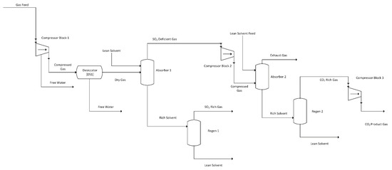
Figure 1.
DES Dual-Stage Absorption System Simplified Flow Diagram.
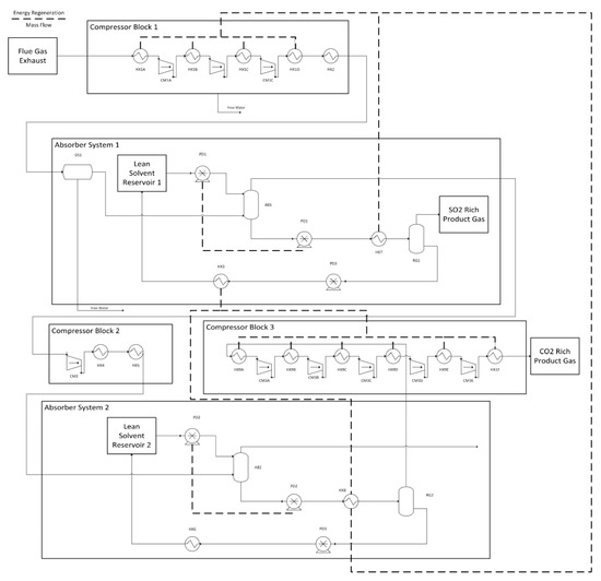
Figure 2.
Process diagram for CO2 and SO2 capture using a two-stage absorption system.
- Henry’s law is valid for all absorption and desorption steps. This is justified by keeping the mole% of SO2 and CO2 below 3%.
- Absorber 2 operates at twice the pressure of absorber 1. This ratio was selected as it was found to be the most efficient in regards to energy demand over a wide variety of CO2 removal rates.
These two assumptions limit the possible applications for most DES systems above 2 and below 30 bars in absorber 2 (where Henry’s law is considered valid with less than 2 mole% solute, and where pressure is above atmospheric). Equations (1)–(3) can be used for determining the removal of CO2 from the feed flue gas from both absorbers. Pressure in absorber 1 is determined from the highest system pressure (which occurs in absorber 2).
where, is the moles CO2 dissolved in the solvent per hour, P is the pressure in the second absorber in bar, H is the Henry’s law constant inbar/(mole frac), C is the total number of components per mole of DES (#HBA + #HBD), is the number of moles of DES used per hour, is the number of moles of CO2 in the feed gas, and is the total moles of gas in the feed stream. This is simply a Henry’s law constant calculation that is expanded for a two-stage system in series. Note that pressure in Equations (1)–(3) refer to the pressure in absorber 2, as it will be consistent with all references to the two-stage absorption model unless otherwise stated. These methodologies will focus primarily on CO2 removal efficiency, as both DES remove more than 99% of SO2 even at low temperatures and low pressures. This assumption is further validated by extensive literature covering absorption phenomena of SO2 into various DES [11,15,23].
1. Gas Compression and Drying
The feed flue gas used was consistent with that used by NETL’s 550MW model plant with approximately 90,000 kmoles of flue gas per hour—of which, 13.76% is CO2 [2]. As CO2 absorption is a physisorption process, flue gas needs to be compressed prior to entering the absorption column, whereas the state-of-the-art system (e.g., CanSolv) does not require a compressed feed. The required pressure is determined from Equations (1)–(3) through iterative numerical solution methods. ASPEN Plus V9 was used to model the number, cost, and duty/power requirement of the compressors needed to achieve the desired operating conditions (the pressure of each absorber unit). Consistent with those designed in the NETL model, the compressors modeled here had mechanical and thermal efficiencies of 97% and 89%, respectively [2]. ASPEN modeling was completed using the Soave-Redlich-Kwong (SRK) property set with default binary interaction parameters. Compression was simulated using the default compressor module using the Polytropic ASME method. Equation (4) shows the power required for compression as a function of operation pressure (which is the pressure in the second absorber).
where, Pc is the compressor power, is the moles CO2 removed from the feed stream per hour, P is the pressure in the second absorber in bar, and is the number of moles of CO2 in the feed gas. The constants in this equation are based off of both the NETL case B11B and ASPEN compressor model [19]. This includes compression of the final product CO2 gas, which is also done in the state-of-the-art system. For a simplified estimation of gas cooling demand, it is assumed that the power required to cool the gas is twice that of the compression power, which was determined from the ASPEN simulations. Heat is recovered from the compressor outlets through heat exchangers that heat various other streams in the system. Figure 2 shows these heat recovery steps. Following compression of the gas, a solid sorbent is used to dry the feed gas in order to preserve the DES solvent, as both DES are hygroscopic [7,24,25]. This unit is modeled as multiple cycled packed bed reactors where overall system performance is considered as constant, and the regeneration energy of the sorbent is assumed to be the latent heat of vaporization of water at atmospheric conditions. Heat duties for both flue and product gases cooling and drying were calculated but found insignificant (at least two orders of magnitude lower) when compared to the other heating duties of the process and the power required for compression and free water removal.
Following the compression and drying process, the feed gas is fed at the specified pressure and 65 °C into the first absorber system. Approximately 93% of the water is removed in the compression process, and overall 99.8% of water is removed before the first absorber by using a desiccator. This results in a flow rate of 9 kmoles water per hour into the absorber unit, which is more than 5000 times lower than the mass flow rate of the DES. Water removal from the DES was not approximated in this analysis since its flow rate was so low and existing literature has concluded that water does not react with the DES examined here, though it can impact thermophysical properties at very high mole fractions [18,21].
2. DES Pumping and Heating
In the process modelling, DES are considered incompressible fluids at constant densities. There is minor change in density over the examined temperature range (25–100 °C) and pressure range (1–50 bar) observed in the literature, but this has minor impact on the overall cost analysis of the system in regards to pumping power [26]. Compression and pumping power required for the DES was calculated using Equation (5).
where, Pp is the pumping power in kW, P is the pressure in the second absorber in bar, is the number of moles of DES used per hour, is the molecular mass of DES in kg/mole, and g is gravitational acceleration (9.81 m/s2). For the selected DES, an operation temperature ranging from 25 to 85 °C was sufficient for solvent regeneration. It is assumed that heat capacities of the DES are constant over the regeneration temperature range. Equation (6) and (7) are used to calculate solvent heating and cooling demand, respectively.
where, Qheat and Qcooling are the heating and cooling powers in kW respectively, is the specfic thermal demand of the solvent in kJ/kg, is the number of moles of DES used per hour, and is the molecular mass of DES in kg/mole. The efficiencies for these processes are considered to be 80%, which is multiplied by 0.5 to account for the dual-stage system that requires the heating and cooling to occur twice. Figure 2 shows this heat recovery networking. Note that units such as heat exchanger 7, which have multiple heat recovery steps are modeled as multiple heat exchangers, but for the purpose of simplicity are shown with a single icon. Heat exchanger sizing, pricing, and optimization was all completed in ASPEN, using the model parameters as those used for gas compression in Section Gas Compression and Drying. For the dual-stage system, a counter-current heat exchanger was used to preheat the cold gas-rich solvent with the regenerated hot solvent. It is assumed that 80% of the total energy is recovered from the preheating stage. Since this occurs twice in the process the entire system requires 40% of its total thermal demand as an input (these are parallel heating processes with the absorption process being in series). Further heat recovery is completed by cooling the compressed gas streams using cool solvent rich DES.
2.4. Process Economics
Data from the literature along with ASPEN Plus V9 was used to price each individual units shown in Figure 1 [27]. The energy associated with this operation cost was calculated and subtracted from the gross plant output. The production cost was then calculated assuming the FGD and CanSolv units were completely replaced with the DES two-stage system. Equations (8)–(13) show these calculations.
Ccapital is the capital cost of the system, PO is the plant output in kWe PP is the the total power required for all pumps in the system, and P is the pressure in the second absorber (the highest pressure in the system). Compressor power, solvent heating, and solvent cooling are all in kWe equivalent and refer to the respectively demand of each operation in the entire process. Gas cooling has been lumped into the compressor power demand, thus the coefficient of 3 (based on the earlier evaluation form Aspen that gas cooling was twice that of compressor power across most of the model’s range). All USD values are shown in June 2011 USD (CEPCI = 592). Equations (8)–(11) are derived from NETL’s Case B11B [2].
PCF is the plant correction factor, which accounts for the varying energy demand of the utilities, PCBC is the plant corrected base cost which adjusts the total capital of the entire plant, with 1915 being the contribution of the base case capital, and Ccapture and Ctotal are the capture and total costs respectively in $/kWe. Base case capital includes all items not related to CO2 or SO2 capture from NETL’s case B11B [2]. As the energy demand for the CO2 and SO2 process changes with operation conditions, the overall energy demand of the plant changes. As such, correction factors are considered to adjust the plant size and gross power output to account for these demands. It is assumed that these relatively small changes (usually less than 10%) result in a linear change in operating and capital costs. All calculations were completed using Matlab2017b. For case B11B, which is subcritical operation of a 550 MWe power plant with carbon capture, the total production cost is 3467 $/kWe—of which, $1915 is not directly attributed to SO2 and CO2 removal.
2.5. Parameters for Sensitivity Analysis
Sensitivity of the proposed model was evaluated by worsening and improving important system parameters to evaluate both the importance of those parameters as well as what direction future works should take in regards to improving system performance. Table 2 shows all values for both the baseline and adjusted scenarios. All values were changed independently of one another for this analysis. Henry’s law constant was considered at 100 and 200 bar/(mole frac). This spans the range of solvents discussed in this study, as well as solvents mentioned in other prominent DES literature [12]. CO2 composition was considered at a range of 8–25%. Though flue gas streams in coal-fired power plants will most likely not reach concentrations this high, this does allow the analysis to glimpse into the system’s viability for other applications, such as biogas separation processes [13]. Molar mass of DES was considered at 200 and 350 g/mol (most DES are combinations of 50–150 g/mol solvents). Heating demand was considered at 18 and 30 kJ/kg. These values will vary with a variety of other parameters such as operation conditions and the solvent’s thermophysical properties. While these thermal demands can reach more than 50 kJ/kg, these changes are still significant relative to the base case conditions.
Table 2.
Sensitivity analysis parameters; using ChCl at 10% CO2 removal, 20,000 kmoles DES/hour.
3. Results and Discussion
3.1. DES Solvent Properties
For this study, solvent density, heat capacity, molar mass, and Henry’s law constant for both CO2 and SO2 are needed to complete the process modelling and process economics. A compiled list of solvent properties is shown in Table 1. This list is a combination of both the COSMOtherm modeling results and other studies on DES properties. Please note that Table 1 uses thermal demand rather than heat capacity. This is simply the total energy required to take the solvent from starting to final temperature in the process (25 to 85 °C). The density and Henry’s law constants are in relative agreement with existing literature, with the modeled values in this study only fluctuating slightly from previously reported results, 1185 compared to 1186 g/L and 170 compared to 175 bars/(mole frac) for model and literature values respectively [18,21]. Henry’s law constant for SO2 for both solvents (METPB:EG and ChCl:Urea) were below 1 bars/(mole frac). This resulted in computational errors in Matlab due to the extremely small amount of SO2 left in the gas phase. Thus, it is assumed that all SO2 will absorb into the DES in the first stage.
3.2. Process Design of Dual-Stage CO2 Absorption in DES
Table 3 and Table 4 show the process modeling results for METPB:EG and ChCl:Urea respectively. The most significant difference between the two processes is operation pressure required to meet the CO2 capture requirements (those set for comparing analysis at 10%, 20% and 30%). METPB:EG requires less pressure to dissolve the same amount of CO2 in an equimolar amount of solvent since it has a higher number of components (one HBA and three HBD compared to one HBA and two HBD) while still having a similar Henry’s law constant. However, ChCl:Urea outperforms the METPB:EG in net plant output due to its lower heating demand and solvent pumping requirements, even though it requires more energy for gas compression. METPB:EG has a far higher molar mass and density, and therefore requires far more energy to pump compared to an equimolar amount of ChCl:Urea.
Table 3.
Dual-Stage Model output for METPB:EG system at 10%, 20%, and 30% CO2 removal.
Table 4.
Dual-Stage Model (Choline Chloride:Urea) system at 10%, 20%, and 30% CO2 removal.
The overall sizes of both systems are determined primarily by the Henry’s law constant. Values smaller than those shown in Table 3 and Table 4 require pressures where the Henry’s law cannot be considered to be consistently accurate. At those smaller system sizes concentrations of CO2 greater than 3% are needed to remove even the lowest amount of CO2 (10%). It is important to also consider that these are simply reference cases of well-established DES, and that this process model is to be used in searching for an applicable DES in the future as new research progresses.
For the total process, the solvent heating into the desorption is the most energy intensive step. This typically accounts for 20–45% of the total energy demand of the system, with variations being due to the wide range of thermal demands required to meet the desorption parameters. Solvent molar mass, Henry’s law constant, and desorption temperature all have a significant impact on the amount of solvent used and the amount of energy required to heat it to fully release the CO2. The compression of the product gas is a significant portion of the overall energy demand as well. These specific conditions for the product gas are considered to match the NETL process report but changing the specifications of the CO2 product would have a significant impact on the total process requirements. The total size of the DES for these particular case studies are relatively feasible (compared to annual production of each chemical) primarily because these chemicals are produced for other applications such as the poultry industry or for antifreeze. For emerging DES, it is important to consider the production demands that would be required for a full-scale application such as gas capture in a power plant.
3.3. Process Economics of Dual-Stage CO2 Absorption in DES
Normalized production cost and normalized plant output for the METPB:EG system are shown in Figure 3. This figure shows the output and cost of the entire power plant assuming that the entire CO2 and SO2 capture system has been replaced with a DES system. Both values are standardized to the base case of B11B. Capture cost increases and net output of the plant decreases as the system size is increased from 20,000 kmoles of DES to 100,000 kmoles DES. These values are normalized to 3467 $/kWe and 550 MWe, respectively. Figure 4 shows the relative efficiency compared to the same case B11B. This relative efficiency is defined as the cost per kWe output. Increasing the size of the system, and consequently decreasing the operation pressure, decreases the relative efficiency of the power plant (energy and capital costs increase more than the reductions caused by a lower operation pressure). A small absorption system (DES less than 40,000 Kmoles) has relative efficiencies above 70%. Table 3 and Table 4 show process and economic data generated for both DES solvents evaluated. Decreasing system size even further would improve these efficiencies by lessening the detrimental impact of solvent heating demand. As the research field surround DES matures and accelerates, it is vital that efforts to apply these solvents are done so efficiently. Therefore, this model could be used to ease solvent screening. To expand upon this, a sensitivity analysis was performed to determine which properties researchers should be focusing on when selecting solvents.
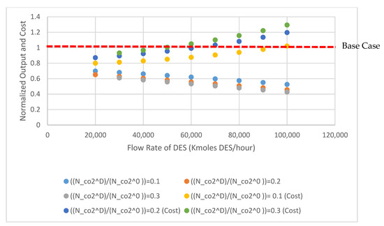
Figure 3.
Normalized plant output and cost for METPB:EG SYSTEM, values for net plant power output and overall cost are normalized to NETL’s case B11B.
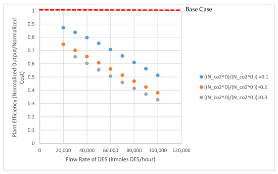
Figure 4.
Relative plant efficiency for the METPB system; efficiency is calculated from the normalized output and cost values in Figure 3.
3.4. Sensitivity Analysis
The sensitivity of the model was evaluated using ChCl:Urea as the base model. A tornado plot is shown in Figure 5 detailing the effect of various parameters on the system. Each specific parameter range is shown in Table 2. As is expected, the Henry’s law constant has a large impact on the system’s economic feasibility (relative cost compared to the baseline to achieve a similar result). For this particular usage of Henry’s law constant (bars/(mole frac)), it is expected that as the value approaches zero the absorbed moles approach infinity. This sensitivity is a result of this mathematical effect, though the overall impact of the ability to dissolve CO2 is obviously important for absorption applications. For most of the DES described in the literature, Henry law constants ranging from 80 to 200 bar/(mole frac) can be expected [11,28]. In a similar fashion, changing the CO2 concentration has an almost equally large impact on system feasibility. Typical CO2 concentration ranges expected in flue gases from coal fired power plants are 10–15%, with this analysis being completed towards the upper end of that range [29]. Changing the heating demand of the solvent, even by a significant amount, does not significantly impact the system pressure. As the field of DES research progresses and solvents are optimized, this heating duty may be more important. But given the wide range of DES evaluated here, its effect is muted.
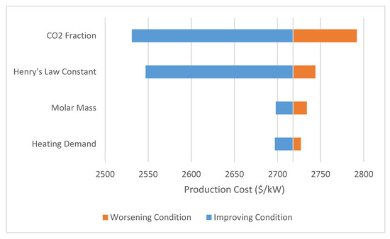
Figure 5.
Sensitivity of analysis to changing solvent parameters; the amount of CO2 present and the Henry’s law constant are the most significant factors affecting price—both of which contribute to operation pressure.
Given the system sensitivity to the operation pressure, factors that lower system operation pressure should be the focus of future research that seeks to apply or evaluate DES for gas capture. To compete with the current state-of-the-art systems, future DES will have to be 2–3 times more efficient at gas capture than choline chloride and urea, with efficiency being the combined effect of all thermophysical properties. Despite the fact that the flue gas stream contains a large amount of inert compounds (approximately 74%), a low concentration of CO2, and is typically exhausted at low pressures, the modeled systems show that DES can be used to obtain relatively comparable results to state-of-the-art CO2 capture technologies. Systems that emit more concentrated CO2 streams would be far more feasible for DES systems to be economically feasible, as shown by the sensitivity analysis. Future research should utilize the model detailed here to screen for solvents that have a low molecular weight, a Henry’s law constant of 80–120 bar/(mole frac) and minimized thermal demands.
4. Conclusions
Though METPB and ChCl solvents have been studied thoroughly for gas capture, evaluation shows that their physical properties prevent them from being economically viable for application to the remediation of flue gas. The Henry law constants and densities are simply too high, requiring high-pressure absorption systems to achieve even 30% CO2 removal. The framework used to evaluate these solvents has shown that significant improvements can be made to the overall system viability by small changes in density, thermal demand between capture and release of gas, and of course the Henry’s law constant. This framework can also be used to quickly screen solvents for potential feasibility in large-scale systems using flue gases. Future works assessing system sustainability can use this framework for narrowing down candidate solvents. Additional work is required for determining DES that would truly out compete state-of-the-art systems.
Author Contributions
Conceptualization, M.T.R.; Methodology, K.M.; Software, K.M.; Validation, K.M. and M.T.R.; Writing—Original Draft Preparation, K.M.; Writing—Review and Editing, M.T.R.; Visualization, K.M.; Supervision, M.T.R.; Project Administration, M.T.R.; Funding Acquisition, M.T.R. All authors have read and agreed to the published version of the manuscript.
Funding
This research was funded by the Ohio Coal Development Office (Project OCDO D-17-01).
Acknowledgments
The authors would like to thank the Ohio Coal Development Office for funding this research. All experiments were completed at the Institute for Sustainable Energy and the Environment while the authors were at Ohio University.
Conflicts of Interest
The authors declare no conflicts in interest.
References
- Rao, A.B.; Rubin, E.S. A technical, economic, and environmental assessment of amine-based CO2 capture technology for power plant greenhouse gas control. Environ. Sci. Technol. 2002, 36, 4467–4475. [Google Scholar] [CrossRef]
- Fout, T.; Zoelle, A.; Keairns, D.; Turner, M.; Woods, M.; Kuehn, N.; Shah, V.; Chou, V.; Pinkerton, L. Cost and Performance Baseline for Fossil Energy Plants Volume 1a: Bituminous Coal (PC) and Natural Gas to Electricity Revision 3; Technical Report No. DOE/NETL-2015/1723; NETL: Pittsburgh, PA, USA, 2015. [Google Scholar]
- Lv, B.; Guo, B.; Zhou, Z.; Jing, G. Mechanisms of CO2 capture into monoethanolamine solution with different CO2 loading during the absorption/desorption processes. Environ. Sci. Technol. 2015, 49, 10728–10735. [Google Scholar] [CrossRef]
- Gouedard, C.; Picq, D.; Launay, F.; Carrette, P.-L. Amine degradation in CO2 capture. I. A review. Int. J. Greenh. Gas Control 2012, 10, 244–270. [Google Scholar] [CrossRef]
- Sexton, A.J.; Rochelle, G.T. Reaction products from the oxidative degradation of monoethanolamine. Ind. Eng. Chem. Res. 2010, 50, 667–673. [Google Scholar] [CrossRef]
- Aaron, D.; Tsouris, C. Separation of CO2 from flue gas: A review. Sep. Sci. Technol. 2005, 40, 321–348. [Google Scholar] [CrossRef]
- Abbott, A.P.; Capper, G.; Davies, D.L.; Rasheed, R.K.; Tambyrajah, V. Novel solvent properties of choline chloride/urea mixtures. Chem. Commun. 2003, 70–71. [Google Scholar] [CrossRef] [PubMed]
- Kareem, M.A.; Mjalli, F.S.; Hashim, M.A.; AlNashef, I.M. Phosphonium-based ionic liquids analogues and their physical properties. J. Chem. Eng. Data 2010, 55, 4632–4637. [Google Scholar] [CrossRef]
- Sze, L.L.; Pandey, S.; Ravula, S.; Pandey, S.; Zhao, H.; Baker, G.A.; Baker, S.N. Ternary deep eutectic solvents tasked for carbon dioxide capture. ACS Sustain. Chem. Eng. 2014, 2, 2117–2123. [Google Scholar] [CrossRef]
- Chen, Y.; Ai, N.; Li, G.; Shan, H.; Cui, Y.; Deng, D. Solubilities of carbon dioxide in eutectic mixtures of choline chloride and dihydric alcohols. J. Chem. Eng. Data 2014, 59, 1247–1253. [Google Scholar] [CrossRef]
- García, G.; Aparicio, S.; Ullah, R.; Atilhan, M. Deep eutectic solvents: Physicochemical properties and gas separation applications. Energy Fuels 2015, 29, 2616–2644. [Google Scholar] [CrossRef]
- Sarmad, S.; Mikkola, J.-P.; Ji, X. Carbon dioxide capture with ionic liquids and deep eutectic solvents: A new generation of sorbents. ChemSusChem 2017, 10, 324–352. [Google Scholar] [CrossRef] [PubMed]
- Ma, C.; Liu, C.; Lu, X.; Ji, X. Techno-economic analysis and performance comparison of aqueous deep eutectic solvent and other physical absorbents for biogas upgrading. Appl. Energy 2018, 225, 437–447. [Google Scholar] [CrossRef]
- Rinaldi, R. Plant biomass fractionation meets catalysis. Angew. Chem. Int. Ed. 2014, 53, 8559–8560. [Google Scholar] [CrossRef] [PubMed]
- Yang, D.; Hou, M.; Ning, H.; Zhang, J.; Ma, J.; Yang, G.; Han, B. Efficient SO2 absorption by renewable choline chloride–glycerol deep eutectic solvents. Green Chem. 2013, 15, 2261–2265. [Google Scholar] [CrossRef]
- Yang, D.; Hou, M.; Ning, H.; Ma, J.; Kang, X.; Zhang, J.; Han, B. Reversible capture of SO2 through functionalized ionic liquids. ChemSusChem 2013, 6, 1191–1195. [Google Scholar] [CrossRef]
- Deng, D.; Liu, X.; Gao, B. Physicochemical properties and investigation of azole-based deep eutectic solvents as efficient and reversible SO2 absorbents. Ind. Eng. Chem. Res. 2017, 56, 13850–13856. [Google Scholar] [CrossRef]
- Leron, R.B.; Caparanga, A.; Li, M.-H. Carbon dioxide solubility in a deep eutectic solvent based on choline chloride and urea at T = 303.15–343.15 K and moderate pressures. J. Taiwan Inst. Chem. Eng. 2013, 44, 879–885. [Google Scholar] [CrossRef]
- Schäfer, A.; Horn, H.; Ahlrichs, R. Fully optimized contracted Gaussian basis sets for atoms Li to Kr. J. Chem. Phys. 1992, 97, 2571–2577. [Google Scholar] [CrossRef]
- Klamt, A.; Schüürmann, G. COSMO: A new approach to dielectric screening in solvents with explicit expressions for the screening energy and its gradient. J. Chem. Soc. Perkin Trans. 1993, 2, 799–805. [Google Scholar] [CrossRef]
- Leron, R.B.; Li, M.-H. Molar heat capacities of choline chloride-based deep eutectic solvents and their binary mixtures with water. Thermochim. Acta 2012, 530, 52–57. [Google Scholar] [CrossRef]
- Fang, Y.; Osama, M.; Rashmi, W.; Shahbaz, K.; Khalid, M.; Mjalli, F.; Farid, M. Synthesis and thermo-physical properties of deep eutectic solvent-based graphene nanofluids. Nanotechnology 2016, 27, 075702. [Google Scholar] [CrossRef] [PubMed]
- Shaoyang, S.; Yanxia, N.; Qiang, X.; Zuchen, S.; Xionghui, W. Efficient SO2 absorptions by four kinds of deep eutectic solvents based on choline chloride. Ind. Eng. Chem. Res. 2015, 54, 8019–8024. [Google Scholar] [CrossRef]
- Van Osch, D.J.G.P.; Zubeir, L.F.; van den Bruinhorst, A.; Rocha, M.A.; Kroon, M.C. Hydrophobic deep eutectic solvents as water-immiscible extractants. Green Chem. 2015, 17, 4518–4521. [Google Scholar] [CrossRef]
- Zhang, Q.; Vigier, K.D.O.; Royer, S.; Jérôme, F. Deep eutectic solvents: Syntheses, properties and applications. Chem. Soc. Rev. 2012, 41, 7108–7146. [Google Scholar] [CrossRef] [PubMed]
- Leron, R.B.; Li, M.-H. High-pressure density measurements for choline chloride: Urea deep eutectic solvent and its aqueous mixtures at T = (298.15 to 323.15) K and up to 50 MPa. J. Chem. Thermodyn. 2012, 54, 293–301. [Google Scholar] [CrossRef]
- Turton, R.; Bailie, R.; Whiting, W.; Shaeiwitz, J.; Bhattacharyya, D. Analysis, Synthesis, and Design of Chemical Process, 4th ed.; Prentice Hall International Series in the Physical and Chemical Engineering Sciences; Prentice Hall: Ann Arbor, MI, USA, 2012; ISBN 978-0-13-261812-0. [Google Scholar]
- Leron, R.B.; Li, M.-H. Solubility of carbon dioxide in a choline chloride–ethylene glycol based deep eutectic solvent. Thermochim. Acta 2013, 551, 14–19. [Google Scholar] [CrossRef]
- Last, G.V.; Schmick, M.T. Identification and Selection of Major Carbon Dioxide Stream Compositions; Technical Report No. PNNL-20493; Pacific Northwest National Laboratory: Richland, WA, USA, 2011. [Google Scholar]


© 2020 by the authors. Licensee MDPI, Basel, Switzerland. This article is an open access article distributed under the terms and conditions of the Creative Commons Attribution (CC BY) license (http://creativecommons.org/licenses/by/4.0/).