Abstract
In many countries the percentage of power electronic interfaced power sources (PEIPS), especially renewable energies like wind power and photovoltaic (PV), has increased significantly during the last decade.Retaining system stability with a declining number of conventional synchronous generators is a new challenge that starts to be addressed by Grid Operators. The existing control schemes used in distributed energy generation inverters generally do not provide significant services to grid stability. This paper focuses on a control scheme that is in many ways similar to the control of conventional power plants, but avoids a higher rating of the inverters which is often required by control approaches emulating the response of a synchronous generator. The control parameters of the proposed scheme are derived analytically and their main dependencies from major system parameters are discussed. An add-on to achieve fault ride through capability for both balanced and unbalanced faults for voltage controlled inverters is presented. Model validation results in a laboratory setup show very good correlation and have proven practicability of the theory as well as fault ride through and islanding capability.
1. Introduction
The total amount of electric energy supplied by PEIPS is rising significantly during the last decade, [1,2,3]. At the same time energy generated by grid forming conventional power plants is reduced with negative impact on grid stability [4]. The traditional common control schemes of renewable energy sources inverters have been derived from the well-known and well proven control schemes from adjustable motor drives. Typically they are mainly current controlled [5,6,7,8]. The current control nature has the significant advantage of precise torque control and excellent inverter protection by limiting the set point values of the controllers. The classical approach of current control works in a rotating reference frame, where the currents become dc quantities under stationary conditions and the integrator part of the controller ensures zero stationary error [8,9]. A different approach of current control is based on a stationary reference frame. In order to achieve zero steady state error with such a controller it must have infinite gain at line frequency resulting in a resonance transfer function [6,8,10]. Although both control schemes look very different at first sight, in Reference [11] it has been shown that the proportional-resonant (PR) control in the stationary reference frame is identical to proportional-integral (PI) control in a rotating reference frame for positive and negative sequence with equal controller gains in both reference frames.
An alternative control concept uses the power quantities directly without controlling currents in a cascaded structure [12,13,14,15]. However, all these control concepts do not provide grid stability in case of grid disturbances, for example, fast frequency or voltage changes. Current or power controlled inverters will keep the desired quantities, current or power, constant during the first transient time. Only in an outer secondary loop typically the set point values may be changed according to some characteristics, that are consistent with grid utility.
Grid stability right now is mainly maintained by the still operating conventional power plants with their inherent grid stabilizing nature of conventional synchronous power generators. The requirements defined in the European Grid Code [16] can be summarized as “grid friendly” behaviour, which supports the functioning of existing conventional power stations, but does not aim to fully replace them. In order to further increase the amount of power electronics interfaced power sources (PEIPS), the corresponding control concepts of the grid connected inverters must change and give a similar inherent stability service as conventional power plants [17]. An ENTSO-E Report on ’High Penetration of Power Electronic Interfaced Power Systems’ has been published in January 2020 [18], defining the requirements for an inverter control that can operate a grid without support from conventional generators.
Voltage controlled inverters are well established in island mode [19,20,21], but rarely applied to grid tied operation [22] where a centralized control of voltage and frequency is not possible. Research on inverter control based on the concept of Virtual Synchronous Machine (VSM) [23,24,25,26,27], show promising results of maintaining grid stability, but these concepts lack the capability to limit the currents in a way needed for todays inverter design. The work described in this paper presents a voltage fed (grid forming) control scheme, that is similar to the conventional primary control of power plants, but avoids a higher rating of the inverters which is often required by control approaches emulating the response of a synchronous generator like VSM. This paper assumes that the input power for the grid connected inverter is freely available by means of power margin, inertia or some suitable energy storage system. The parameters of the presented scheme are given in an analytically form showing the dependence of key parameters on desired response behaviour. Voltage sources as well as voltage controlled inverters usually suffer from high short circuit currents. This paper presents in addition a robust current limiter add on in order to reduce the fault current to similar values as known from current controlled inverters. Unlike other current limiting control concepts like dynamic pulse inhibition the presented fault limiter maintains sinusoidal wave forms.
In Section 2 the basic dependencies of power quantities on inverter voltage magnitude and phase are presented as a basis for primary control. The proposed inverter control for frequency and voltage magnitude derived from References [22,28,29] is given in Section 3. This section shows new derivation of the analytical design of droop control parameters and their dependencies on system parameters. The control system is extended by a novel fault current limiting structure, that prevents the inverter from excessive overcurrents typical for voltage fed control systems. The total system achieves excellent grid stabilizing behaviour while maintaining good fault current limitation similar to current controlled structures. In Section 4 the simulation results are confirmed by laboratory tests.
2. Basic Primary Control
In general, the simplified equivalent circuit shown in Figure 1 applies for grid connected inverters with the appropriate phasor diagram, where , and are the complex phasors of inverter voltage, grid voltage and grid current respectively. The typical line filter (LCL) is simplified to a resulting longitudinal impedance. The influence of the filter capacitor on grid stability issues can be neglected for most issues.
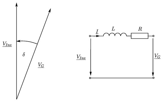
Figure 1.
Equivalent circuit and phasor diagram.
The active and reactive per unit power can be derived from the per unit voltage amplitudes on both sides, their corresponding voltage angle and the filter impedances
where p and q represent the per unit active and reactive power respectively; and represent the relative inductive and resistive short circuit voltage drop of the filter impedance; and represent the per unit magnitude of inverter and line voltage respectively; represent the voltage angle, angle between inverter and line voltage phasor. Typically the voltage angle between inverter and grid voltage is small, so that and cos . In addition the ohmic part of resulting filter impedance is small compared to the inductive part.
These basic equations show the basics of grid control, the active power p mainly depends on the voltage angle and the reactive power q mainly depends on the difference of voltage amplitudes. Both equations are well decoupled as long as the ohmic part of the filter impedance can be neglected. In [20,21,30,31,32,33] a power transformation is proposed in case of non-negligible resistive impedance. In this case the desired active and reactive power are transformed to new decoupled virtual power quantities (p′, q′), that can be calculated similar to Equation (3) and be controlled by voltage angle and voltage amplitude with good decoupling.
where represent the angle of line filter impedance.
The classical primary control of power plants uses a droop control for frequency and voltage magnitude in dependence of active and reactive power respectively. The frequency droop slope is usually in the range of 2–6% depending on the type of power plant, see Figure 2.
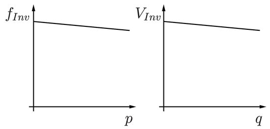
Figure 2.
Droop control.
This droop control of frequency results in a load share according to their p-f-curve and keeps inherently synchronism of the plants. Under stationary conditions each power plant delivers the amount of power according to its individual p-f-curve. Using proper filter coefficients and adjusting the p-f-curve by a secondary control the time behaviour and the load share of the plants can be controlled safely with regard to the specific power plant and an overall control target [34].
In practice in Europe only in rare cases frequency deviations greater than 100 mHz are observed in the grid. This corresponds to power changes less than 4% due to primary control. This inherent grid stabilizing feature shall be maintained by the proposed inverter control scheme. The inverter control generates set values for frequency and voltage amplitude. In this manner it can be viewed as a rude implementation of a virtual synchronous machine. However the aim is not to act as close as possible to a real synchronous generator but to extract the essential properties to service grid stability.
3. Control of Frequency and Voltage
3.1. Frequency Control
The resulting block diagram of control scheme of inverter output frequency is given in Figure 3. The error signal between the active power set point and the actual measured filtered power generates via the gain of the frequency droop an add-on frequency , changing the voltage angle until the error is zero under stationary conditions. The calculated power is filtered with a first order low pass filter in order to give a good decoupling and emulate the desired amount of inertia. The open loop transfer function is given by:
where represents the slope of droop control; s represents the Laplace operator. For well damped response a phase margin of 60 °C is suitable, resulting in a gain of
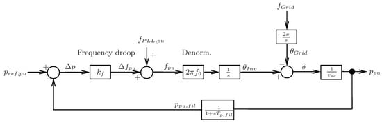
Figure 3.
Basic frequency control.
The resulting gain, the slope of droop control, is proportional to the short circuit voltage of resulting filter impedance and inversely proportional to the filter time constant of measured active power. The closed loop transfer function with this droop slope results in:
having the poles at
resulting in a damping factor of d = 0.5. In order to compensate the zero of the closed loop transfer function a set point filter with is applied.
At a line frequency of and an active power filter time constant of , the resulting slope is only that is far away from typical values of conventional power plants. This extremely low droop results in overload conditions in case of frequency changes in the grid since the inverter changes its frequency only marginally.
In References [22,28,29] it has been proposed to extend the basic frequency droop control by an additional direct path, that acts as feed forward term from the power error directly on the voltage phase see Figure 4. This is generally identical to a differential action of the power error onto the frequency. So far no analytical gains design for this structure has been published showing the main dependencies of control gains on system parameters. Looking in Figure 3 at the droop control, the de-normalization and the integrator as a controller and the rest as a plant, then it is straightforward to change the present integral controller to a proportional integral (PI) controller. Using again the set point filter and compensating the pole of the plant with the zero of the PI controller, , results in a proportional gain of
and a closed loop transfer function of
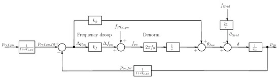
Figure 4.
Enhanced frequency control with phase intervention.
The resulting phase margin is 90 °C, the closed loop function represents a first order low pass filter. The additional feed forward path onto the inverter voltage phase gives excellent damping independent of the chosen active power filter time constant. The frequency droop slope now can be set similar to power plants maintaining a well damped response. Usually the response time is now very fast, it can be reduced to a desired value with respect to the emulated inertia by means of an additional set point filter, that determines the desired overall time constant of the frequency control system.
3.2. Voltage Control
According to (3) the voltage difference of inverter and grid voltage is proportional to the reactive power. Typically the amount of reactive power will be set as a function of grid voltage, see Figure 2, aiming to stabilize the grid voltage to desired values.
Operating the inverter like a voltage source with adjustable frequency, phase and amplitude, the inverter inherently stabilizes grid frequency and voltage. A grid frequency change will immediately change the active power and a voltage sag will immediately change the reactive power. This nature well known from synchronous generators stabilizes the grid inherently. This feature should be retained by modern control strategies in order to offer suitable grid service.
3.3. Fault Ride Through Control
Voltage controlled inverters on the other side are known to cause excessive fault currents due to their typical low short circuit impedance given by the line filter impedance. In the following an easy to implement and robust fault current control is proposed. Since the filter impedance is well known, the stationary current in case of a fault can be limited just by limiting the voltage difference across the filter impedance. Neglecting the ohmic part of the filter impedance, the maximum allowable voltage drop is
where represents the maximum allowed reactive current. With respect to the maximum inverter current the remaining active current has to be limited to
with
Typically a reactive current feeding the fault is given priority. The current limiter is executed in the rotating reference frame ( coordinates). The limiter in Figure 5 limits first the d-component of the filter voltage determining the reactive current. The q-component of the filter voltage determining the active power output is additionally reduced if necessary, so that the total current remains within the given limits of the inverter.
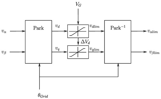
Figure 5.
Static current limiting control of voltage fed inverter.
This limitation of filter impedance voltage ensures static current limitation, but results—like a step change applied to an inductive load—in high dynamic current overshoot and low damped line frequent oscillating currents at fault entry and fault clearing. Suitable damping and very low overshoot is achieved by a feed back network, that feeds the low pass filtered derivatives of the current back to the inverter voltages.
Each transfer function of the damping network consists of a second order low pass filter to prevent any unwanted high frequency excitation but enabling damping of line frequent oscillations and a derivative block for the main damping purpose.
The three time constants for each transfer function have been optimized for well damped response with low overshoot on fault entry and fault clearing. The sign for has to be negative, while the sign for the other transfer functions is positive. The fault ride through (FRT) add on circuit shown in Figure 6 is practically ineffective under normal stationary conditions or slow changing conditions. Under low voltage fault ride through (LVFRT) conditions it limits the current with inductive current priority and well damped response. Figure 7 shows the simulation result of a symmetrical LVFRT event. The voltage at the point of common coupling (PCC) during grid connected condition with full load drops down to about 50% of nominal voltage. During the fault the inductive current rises to 1 pu, the active current is reduced to maintain a typical maximum limit of total current of 1.2 pu. After clearing of the fault the old operating point is recovered fast. No significant overcurrents can be observed despite of the voltage fed nature of the inverter control system, while other published voltage fed control systems, like Virtual Synchronous Machine [23], have shown peak currents in the range of 2–3 pu.
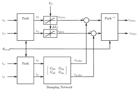
Figure 6.
Fault ride through (FRT) control of voltage fed inverter.
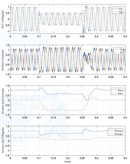
Figure 7.
Simulation result of low voltage fault ride through.
Figure 8 shows the simulation result of an islanding event. Prior islanding an active current of 1 pu is delivered to the grid. After islanding a load of about 50% is connected to the islanded network. As a result the frequency slightly rises according to the p-f curve.
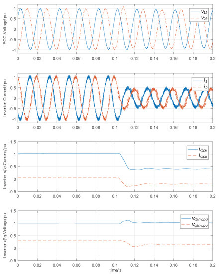
Figure 8.
Simulation result of an islanding event.
For proper behaviour at unsymmetrical faults the structure is extended by a feed forward negative sequence control. The inverter voltage is changed so that a desired virtual impedance is achieved, which is typically 0.5 pu. The negative sequence voltage of the inverter results in
The total negative sequence component is considered in the positive sequence filter voltage limiter (Figure 6), so that the maximum allowable positive sequence filter voltage is reduced accordingly.
4. Laboratory Results
The test bench as shown in Figure 9 consists of a back to back 11 kVA inverter, a grid representation and a fault branch. The impedance of the grid and the fault branch can be configured in a wide range. The bench has been configured to emulate a real 3 MW wind power plant with equal p.u. values for filter and grid impedances, same switching frequency and same filter resonance frequencies. In order to model real world values of the transformers, the transformers itself have been designed to offer low short circuit impedance, that has been artificially increased by external chokes with low resistive component. The system parameters are given in Table 1.
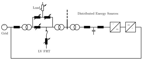
Figure 9.
Single line diagram of test bench.

Table 1.
System Parameters.
The controller for the inverter is based on a dual core signal controller of the type TMS320F28379D from Texas Instruments. The code of the main control functions has been automatically generated from the simulation structure. The inverter protection functions, A/D conversion, pulse width modulation, state machine and communication tasks have been developed separately [35].
Figure 10 shows the laboratory result of the LVFRT test. The residual fault grid voltage has been set to 50% by means of a short circuit impedance equal to the grid impedance. With the fault entry the reactive current rises fast to about 1 pu and the active current is reduced almost to zero. After the fault is cleared the initial operating condition is retained. The laboratory result shows good agreement with the simulation results. Some difference is present due to a minor mismatch of line filter impedance. Figure 11 shows the laboratory result of an islanding event. During this event no change in control structure happens. The load is only half of the load supplied to the grid prior the islanding event. As a result the frequency slightly shifts upwards according the applied p-f-curve. This rise has be limited in a second stage by appropriate limiting or freezing of (Figure 2). A direct comparison between simulation and laboratory result for the symmetrical LVFRT, unsymmetrical LVFRT and islanding event is shown in Figure 12, Figure 13 and Figure 14 respectively. In case of the unsymmetrical fault, the negative sequence component of voltage at the PCC rises up to about 25% while the positive sequence component falls down accordingly. Due to the negative sequence control the negative sequence component of current rises up to about 50%. The positive sequence current is reduced accordingly, so that the stationary total current amplitude is not exceeded beyond the implemented fault current limit. The current transients are comparable with results, that have been published for conventional current control schemes as dq-control in the synchronous reference frame or PR-control in the stationary reference frame [36] using similar switching frequencies typical for high power wind power plants.
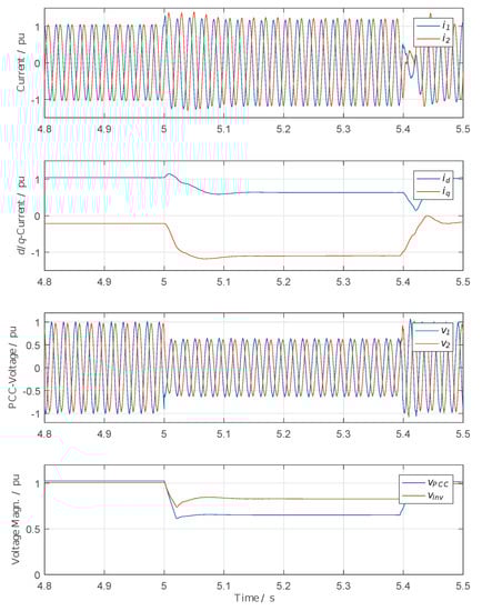
Figure 10.
Laboratory result of low voltage fault ride through.

Figure 11.
Laboratory result of an islanding event.
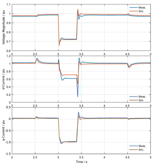
Figure 12.
Comparison between simulation and laboratory result for LVFRT event.
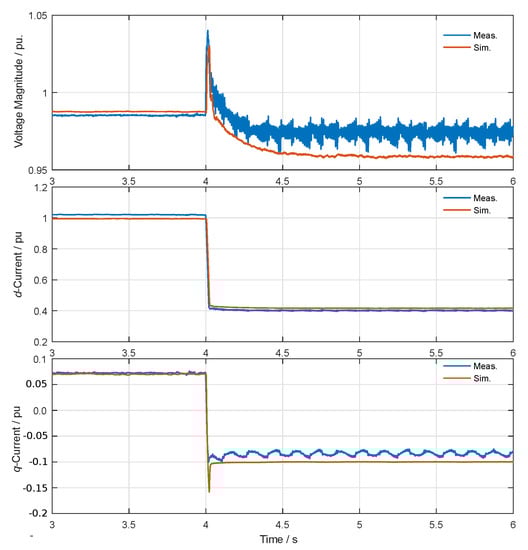
Figure 13.
Comparison between simulation and laboratory result for islanding event.
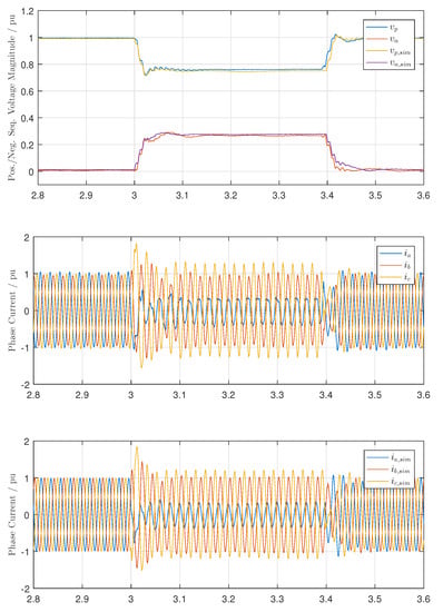
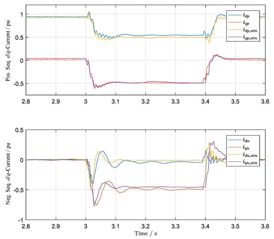
Figure 14.
Comparison between simulation and laboratory results for unsymmetrical LVFRT.
5. Conclusions and Future Work
It has been shown that inverters feeding renewable energies—for example, wind power and PV—to the grid can be controlled in a voltage fed manner like conventional power plants. The control concept works both in grid connected mode as in islanded mode without topology change of the control structures. An analytical design of the droop control parameters with phase intervention has been presented and their dependencies on system parameters are shown. A suitable limiter of the filter impedance voltage complemented with a differential damping network and a negative sequence control enables the important competitive fault ride through capability. In addition the control structure shows seamless transitions during islanding events. Laboratory tests have been performed for islanding events as well as for LVFRT events including unsymmetrical fault conditions. The laboratory results have been in good agreement with the simulation results. The presented simple and robust voltage fed control scheme provides significant service to grid stability without the need for inverter over-sizing beyond industrial standards. The main control scheme is identical for grid tied operation as well as for islanded operation. There is no need anymore for fast islanding detection and reconfiguration of the control scheme as for classical current controlled solutions.
Future work will first focus on increasing the damping of the negative sequence current control and further decreasing the peak transient currents during unsymmetrical faults. In a second stage the research group will focus on the behaviour during parallel operation with different current controlled and voltage fed PEIPS.
Author Contributions
Conceptualization, formal analysis, investigation and writing original draft preparation N.K.; simulation and validation, data curation, writing–review, visualization, N.K., N.G. and J.F.; supervision, N.K. and J.F.; project administration and funding acquisition, J.F. All authors have read and agreed to the published version of the manuscript.
Funding
This research project was funded by the German Federal Ministry for Economic Affairs and Energy, under grant no. 0325935B.
Conflicts of Interest
The authors declare no conflict of interest. The funders had no role in the design of the study; in the collection, analyses, or interpretation of data; in the writing of the manuscript, or in the decision to publish the results.
References
- Zobaa, A.F. An overview of the different situations of renewable energy in the European Union. In Proceedings of the 2005 IEEE Russia Power Tech, St. Petersburg, Russia, 27–30 June 2005; pp. 1–5. [Google Scholar]
- Hales, D. Renewables 2018 Global Status Report; Renewable Energy Policy Network: Paris, France, 2018. [Google Scholar]
- Newbery, D.; Pollitt, M.G.; Ritz, R.A.; Strielkowski, W. Market design for a high-renewables European electricity system. Renew. Sustain. Energy Rev. 2018, 91, 695–707. [Google Scholar] [CrossRef]
- IRENA; IEA; REN21. Renewable Energy Policies in a Time of Transition; Technical Report; IRENA: Abu Dhabi, UAE, 2018. [Google Scholar]
- Blaabjerg, F.; Teodorescu, R.; Liserre, M.; Timbus, A.V. Overview of Control and Grid Synchronization for Distributed Power Generation Systems. IEEE Trans. Ind. Electron. 2006, 53, 1398–1409. [Google Scholar] [CrossRef]
- Busada, C.A.; Jorge, S.G.; Solsona, J.A. Resonant Current Controller With Enhanced Transient Response for Grid-Tied Inverters. IEEE Trans. Ind. Electron. 2018, 65, 2935–2944. [Google Scholar] [CrossRef]
- Pérez-Estévez, D.; Doval-Gandoy, J.; Yepes, A.G.; López, Ó. Positive- and Negative-Sequence Current Controller With Direct Discrete-Time Pole Placement for Grid-Tied Converters with LCL Filter. IEEE Trans. Power Electron. 2017, 32, 7207–7221. [Google Scholar] [CrossRef]
- Timbus, A.; Liserre, M.; Teodorescu, R.; Rodriguez, P.; Blaabjerg, F. Evaluation of Current Controllers for Distributed Power Generation Systems. IEEE Trans. Power Electron. 2009, 24, 654–664. [Google Scholar] [CrossRef]
- Leonhard, W. Control of Electrical Drives, 2nd ed.; Springer: Berlin/Heidelberg, Germany, 1996. [Google Scholar]
- Schiesser, M.; Wasterlain, S.; Marchesoni, M.; Carpita, M. A Simplified Design Strategy for Multi-Resonant Current Control of a Grid-Connected Voltage Source Inverter with an LCL Filter. Energies 2018, 11, 609. [Google Scholar] [CrossRef]
- Teodorescu, R.; Liserre, M.; Rodriguez, P. Grid Converters for Photovoltaic and Wind Power Systems; John Wiley & Sons: Hoboken, NJ, USA, 2011; Volume 29. [Google Scholar]
- Cichowlas, M.; Malinowski, M.; Kazmierkowski, M.P.; Blaabjerg, F. Direct power control for three-phase PWM rectifier with active filtering function. In Proceedings of the Eighteenth Annual IEEE Applied Power Electronics Conf. and Exposition, APEC ’03, Miami, FL, USA, 9–13 February 2003; Volume 2, pp. 913–918. [Google Scholar]
- Malinowski, M.; Kazmierkowski, M.P. DSP implementation of direct power control with constant switching frequency for three-phase PWM rectifiers. In Proceedings of the IEEE 2002 28th Annual Conference of the Industrial Electronics Society, Sevilla, Spain, 5–8 November 2002; Volume 1, pp. 198–203. [Google Scholar]
- Yin, H.; Dieckerhoff, S. Experimental comparison of DPC and VOC control of a three-level NPC grid connected converter. In Proceedings of the IEEE 6th International Symposium on Power Electronics for Distributed Generation Systems (PEDG), Aachen, Germany, 22–25 June 2015; pp. 382–384. [Google Scholar]
- Mulolani, F.; Armstrong, M. Space vector modulation direct power control of grid-connected photovoltaic converter with reactive power compensation. In Proceedings of the 7th IET International Conference on Power Electronics, Machines and Drives (PEMD 2014), Manchester, UK, 8–10 April 2014; pp. 1–6. [Google Scholar]
- European Commission. COMMISSION REGULATION (EU) 2016/631 of 14 April 2016 establishing a network code on requirements for grid connection of generators. Off. J. Eur. Union 2016.
- Weise, B.; Korai, A.; Constantin, A. Comparison of Selected Grid-Forming Converter Control Strategies for Use in Power Electronic Dominated Power Systems. In Proceedings of the 18th Wind Integration Workshop, Dublin, Ireland, 16–18 October 2019. [Google Scholar]
- European Network of Transmission System Operators for Electricity (ENTSO-E). High Penetration of Power Electronic Interfaced Power Systems. In Workshop on High Penetration of Power Electronic Interfaced Power Sources and the Potential Contribution of Grid Forming Converters; ENTSO-E: Brussels, Belgium, 2020. [Google Scholar]
- Lopes, J.A.P.; Moreira, C.L.; Madureira, A.G. Defining control strategies for MicroGrids islanded operation. IEEE Trans. Power Syst. 2006, 21, 916–924. [Google Scholar] [CrossRef]
- De Brabandere, K.; Bolsens, B.; Van den Keybus, J.; Woyte, A.; Driesen, J.; Belmans, R. A Voltage and Frequency Droop Control Method for Parallel Inverters. IEEE Trans. Power Electron. 2007, 22, 1107–1115. [Google Scholar] [CrossRef]
- Yao, W.; Chen, M.; Matas, J.; Guerrero, J.M.; Qian, Z. Design and Analysis of the Droop Control Method for Parallel Inverters Considering the Impact of the Complex Impedance on the Power Sharing. IEEE Trans. Ind. Electron. 2011, 58, 576–588. [Google Scholar] [CrossRef]
- Engler, A.; Soultanis, N. Droop control in LV-grids. In Proceedings of the International Conference Future Power Systems, Amsterdam, The Netherlands, 16–18 November 2005; p. 6. [Google Scholar]
- Beck, H.-P.; Hesse, R. Virtual Synchronous Machine. In Proceedings of the 9th International Conference Electrical Power Quality and Utilisation, Barcelona, Spain, 9–11 October 2007. [Google Scholar]
- Li, C.; Cvetkovic, I.; Burgos, R.; Boroyevich, D. Assessment of Virtual Synchronous Machine based Control in Grid-Tied Power Converters. In Proceedings of the 2018 International Power Electronics Conference (IPEC-Niigata 2018 -ECCE Asia), Niigata, Japan, 20–24 May 2018; pp. 790–794. [Google Scholar]
- Mo, O.; D’Arco, S.; Suul, J.A. Evaluation of Virtual Synchronous Machines with Dynamic or Quasi-Stationary Machine Models. IEEE Trans. Ind. Electron. 2017, 64, 5952–5962. [Google Scholar] [CrossRef]
- Zhan, W.; Wu, Z. Virtual Synchronous Generator Design Method Based on Stable Voltage and Frequency of the Machine. In Proceedings of the 2016 8th International Conference on Intelligent Human-Machine Systems and Cybernetics (IHMSC), Hangzhou, China, 27–28 August 2016; Volume 2, pp. 480–483. [Google Scholar]
- Ierna, R.; Zhu, J.; Roscoe, A.J.; Yu, M.; Dysko, A.; Booth, C.D.; Urdal, H. Effects of VSM convertor control on penetration limits of non-synchronous generation in the GB power system. In Proceedings of the 15th Wind Integration Workshop, Vienna, Austria, 15–17 November 2016. [Google Scholar]
- Engler, A. Device for Equal-Rated Parallel Operation of Single-or Three-Phase Voltage Sources. U.S. Patent 6693809, 17 February 2004. [Google Scholar]
- Strauss, P.; Engler, A. AC coupled PV hybrid systems and microgrids-state of the art and future trends. In Proceedings of the 3rd World Conference Photovoltaic Energy Conversion, Osaka, Japan, 11–18 May 2003; Volume 3, pp. 2129–2134. [Google Scholar]
- Vasquez, J.C.; Guerrero, J.M.; Gregorio, E.; Rodriguez, P.; Teodorescu, R.; Blaabjerg, F. Adaptive droop control applied to distributed generation inverters connected to the grid. In Proceedings of the IEEE International Symposium on Industrial Electronics, Cambridge, UK, 30 June–2 July 2008; pp. 2420–2425. [Google Scholar]
- Bevrani, H.; Shokoohi, S. An Intelligent Droop Control for Simultaneous Voltage and Frequency Regulation in Islanded Microgrids. IEEE Trans. Smart Grid 2013, 4, 1505–1513. [Google Scholar] [CrossRef]
- Zhong, Q.C.; Zeng, Y. Parallel operation of inverters with different types of output impedance. In Proceedings of the 39th Annual Conference of the IEEE Industrial Electronics Society 2013, Vienna, Austria, 10–13 November 2013; pp. 1398–1403. [Google Scholar]
- Zhong, Q.C.; Zeng, Y. Universal Droop Control of Inverters With Different Types of Output Impedance. IEEE Access 2016, 4, 702–712. [Google Scholar] [CrossRef]
- Li, D.; Zhao, B.; Wu, Z.; Zhang, X.; Zhang, L. An Improved Droop Control Strategy for Low-Voltage Microgrids Based on Distributed Secondary Power Optimization Control. Energies 2017, 10, 1347. [Google Scholar] [CrossRef]
- Kisser, A.; Engel, M.; Rezai, L.; Andrejewski, M.; Fortmann, J.; Schulte, H. A Test-bed System for Validation of Ancillary Services of Wind Power Plants under Realistic Conditions. In Proceedings of the 16th Int’l Wind Integration Workshop, Berlin, Germany, 25–27 October 2017. [Google Scholar]
- Bottrell, N.; Green, T.C. Comparison of Current-Limiting Strategies During Fault Ride-Through of Inverters to Prevent Latch-Up and Wind-Up. IEEE Trans. Power Electron. 2014, 29, 3786–3797. [Google Scholar] [CrossRef]


© 2020 by the authors. Licensee MDPI, Basel, Switzerland. This article is an open access article distributed under the terms and conditions of the Creative Commons Attribution (CC BY) license (http://creativecommons.org/licenses/by/4.0/).