Abstract
A grid connected inverter usually requires voltage and current measurements to control the active and reactive powers as well as the inverter output currents. While voltage sensors are essential to obtain reliable information on the phase angle, these additional components certainly increase the production costs and complexity. In this paper, a voltage-sensorless control scheme for a grid connected inverter using a disturbance observer (DOB) is presented. The grid voltages are estimated by DOB in the stationary reference frame using the current measurements and reference signals. Even though the DOB estimates the grid voltages with reasonable accuracy in the presence of the uncertainty such as the unbalanced condition and harmonic distortion, the resultant waveform shows a phase lag depending on the estimation bandwidth. To overcome this limitation, a phase lead compensation is introduced. By using these techniques, the phase angle of grid voltages can be completely restored even if the phase angle of grid is initially unknown. The proposed scheme is simple and straightforward. In addition, it does not require any additional hardware. The feasibility of the proposed voltage-sensorless control scheme is demonstrated through simulations and experiments using 2 kVA prototype inverter.
1. Introduction
Recently, distributed generations (DGs) using renewable energy resources, which include the wind power and photovoltaic generation, have been received an increased attention. A primary objective in future electrical network is to maximize the penetration of DG systems in constructing the microgrid in a way that enhances the overall grid stability and reliability [1]. Because most DGs operate in a grid connected mode, single-phase or three-phase grid connected inverters have become key power electronic interfaces between DG and the utility grid [2,3,4,5,6,7,8,9,10]. The main goal of grid connected inverters is to inject the current into the electrical power grid with high performance in the sense of a fast dynamic response, robustness to disturbance, and zero tracking error. The power quality of the injected current should be sufficiently high even if the grid voltages encounter uncertain disturbances such as the harmonic distortion and imbalance. In addition to those properties, the pulsewidth modulation (PWM) grid connected inverter should provide essential functions such as the grid synchronization, the control of the active power, and the injection of the reactive power under specific condition to meet the grid codes.
Undesirable harmonic contents in electrical system disrupt power transformer operation and produce excessive power dissipation in the transmission lines [2]. Moreover, the harmonic pollution leads to many critical problems such as the distorted grid voltages, malfunction of the high accuracy equipment, and damage on the electrical systems [11]. For this reason, the harmonic restriction standards such as IEEE-519 or IEC 61000-3-2 have been published to limit the amount of harmonic current injected into utility grid [12]. In the same vein, many researchers have investigated the strategies to improve the power quality of the grid connected inverter by mitigating the current harmonics [11,12,13,14,15,16,17,18]. As a selective harmonic compensation scheme, a proportional integral (PI)-resonant current controller has been presented to compensate low-order harmonic terms selectively [13,16]. As an alternative method, nonselective harmonic compensation techniques such as the sliding mode control [11], predictive control [17], and repetitive control [18] have been designed.
As the expansion of DG systems progresses rapidly, the economic feasibility such as the manufacturing cost and system size has become another desirable feature in grid connected inverters. Less feedback sensors often lead to smaller size of hardware and lower cost [1]. To maximize the efficiency and performance, most of grid connected inverters employ three types of sensors in their structure which are the DC link voltage sensor, the grid voltage sensors, and current sensors [19].
Meanwhile, there have been attempts to eliminate some of these sensors in power electronics converters [19,20,21,22,23]. These studies pursue to reduce the system complexity in PWM rectifiers or inverters, while still retaining the system performance and reliability. To allow the grid voltage sensorless operation in single-phase grid connected converters, the voltage estimation scheme based on the measured currents and converter parameters has been proposed [20]. The voltage estimation from the estimated instantaneous active and reactive powers has been studied for PWM converters [21]. However, since this scheme requires numerical differentiation, high-frequency noises may degrade the estimation accuracy.
A nonlinear Luenberger type observer has been presented to eliminate the line voltage sensors in three-phase voltage source converter [22]. To estimate the equivalent grid impedance and equivalent grid voltage, an extended Kalman filter has been introduced [23]. Although these schemes give a relatively good estimation performance, it is not easy to implement these schemes in commercial systems due to the algorithm complexity and computational burden. Furthermore, these methods have not been verified under various grid conditions including the grid uncertainties such as the imbalance and harmonic distortion.
As another approach, numerical algorithms such as the Newton–Raphson optimization, was introduced to estimate the grid voltage in three-phase grid connected voltage source converters [19]. However, it is well known that this scheme is quite complicated because nonlinear interconnected equations should be solved by iteration. In addition, the convergence should be carefully considered to get the solution with an acceptable accuracy. Grid synchronization method without the line voltage sensors has been presented by using an adaptive observer to estimate unknown dynamics [1].
As an effective way of observing external disturbances in systems, the estimation principle based on DOB has recently been studied [24]. In theory, the DOB uses the information on the output measurement and known control input together with the system inverse model to estimate the unknown disturbances. In view of the state equation model of a grid connected inverter, the grid voltages can be regarded as the disturbance, which enables the estimation of grid voltages through the DOB.
To retrench the manufacturing cost without the loss of reliability, this paper proposes a voltage-sensorless control scheme for a grid connected inverter using DOB. The proposed scheme mainly consists of two parts: a current control design based on the proportional-resonant (PR) controller and the estimator design of grid voltages based on the DOB. Generally, to synchronize the grid connected inverters to utility grid, a phase-locked loop (PLL) algorithm using the measured voltages is applied because of its simplicity and performance. To obtain the grid voltage information without voltage sensors, the proposed scheme employs the DOB based estimation using the current measurements and reference signals. The estimated grid voltages exhibit the phase lag from actual grid voltages due to the bandwidth limit of the DOB. This phase delay is compensated before the estimated grid voltages are used in the PLL algorithm to determine the phase angle of grid voltages. To validate the effectiveness of the proposed voltage-sensorless control scheme, 2 kVA prototype grid connected inverter has been constructed using the digital signal processor (DSP) TMS320F28335 (Texas Instruments, Dallas, TX, USA) [25]. Through the comparative simulations and experiments, it is verified that the proposed scheme works usefully with a reasonable reliability even under the grid uncertainties such as the imbalance or harmonic distortion.
2. Modeling of a Grid Connected Inverter
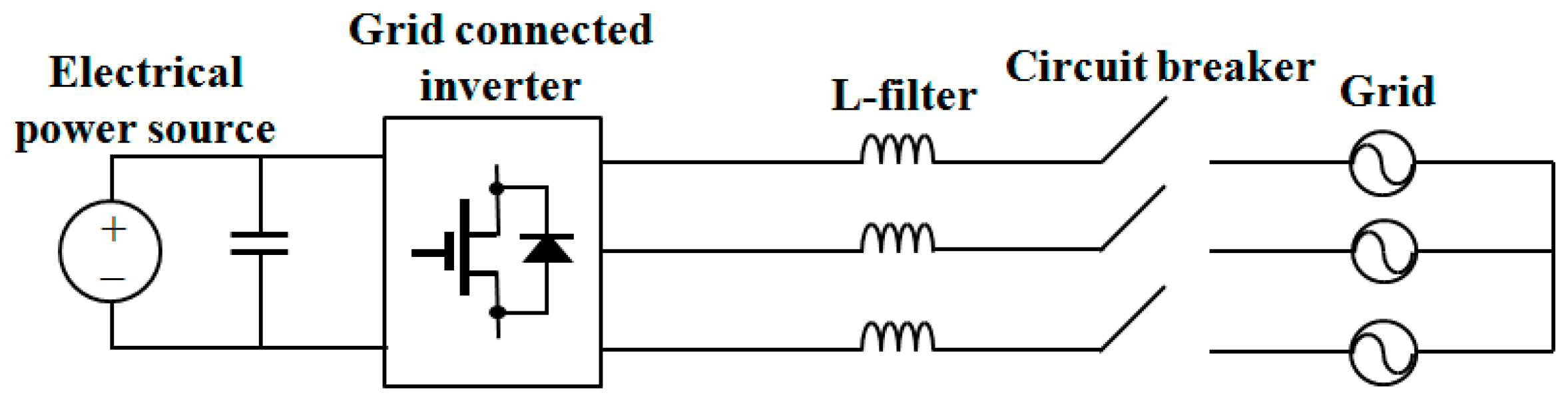
Figure 1 shows the configuration of a grid connected inverter connected to the utility grid through an L filter. In the stationary reference frame, the mathematical model of three-phase grid connected inverter is described as follows:
where the subscript “αβ” denotes the stationary reference frame; and are the q-axis and d-axis inverter voltages in the stationary frame, respectively; and are the q-axis and d-axis inverter currents in the stationary frame, respectively; and are the q-axis and d-axis grid voltages in the stationary frame, respectively; and R and L represent the equivalent resistance and inductance of the filter and connection cables.
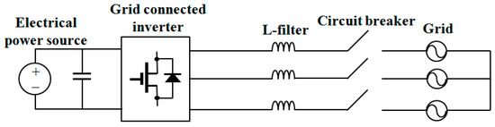
Figure 1.
Configuration of a grid connected inverter.
To regulate the active and reactive powers of DG system, the current of a grid connected inverter should be controlled with the synchronization to grid voltage. To alleviate the system instability due to the absence of phase angle information at the initial stage, the proposed scheme uses a PR current controller in the stationary reference frame, which contributes to a stability enhancement by minimizing the transformation with phase angle information.
In the stationary reference frame, a PR current controller is expressed as follows:
where , , the symbol “*” denotes the reference quantities, is a Laplace operator, and is the output of the PR controller. In Equation (3), is the transfer function of the PR controller expressed as:
where and are the proportional and resonant gains of the PR controller, respectively; is the bandwidth; and is the center frequency. To determine the eventual reference voltages of a grid connected inverter, the grid voltages are added into by a feedforward manner as follows:
where and is the reference voltages.
The reference voltages are applied through the symmetrical space vector PWM technique. For further development of the DOB using the system inverse model, it is simply assumed that the reference voltages are applied to the terminals of the inverter without any loss and deformation in the PWM inverter, that is, and . In addition, from Equations (1) and (2), the system model of a grid connected inverter is rewritten as follows:
where , , and .
3. Estimation of Grid Voltage with Disturbance Observer
In this section, a DOB based control structure and grid voltage estimation process are described. From Equations (1) and (2), the state equation of a grid connected inverter can be expressed as follows:
where , , , and is regarded as an external disturbance in the state equation.
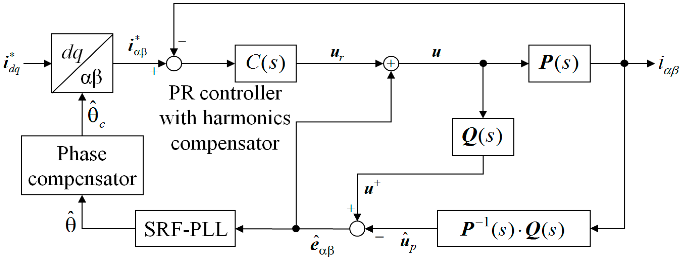
The objective of the control design is to steer the state to its desired reference value in the presence of external disturbance such as the harmonics and imbalance, and at the same time, to obtain the phase angle information by estimating the grid voltages with the DOB. Figure 2 shows the overall block diagram for the proposed voltage-sensorless control scheme. The basic concept of the DOB is that if the disturbed system input can be estimated, the disturbance can also be estimated by comparing with the known control input [26].
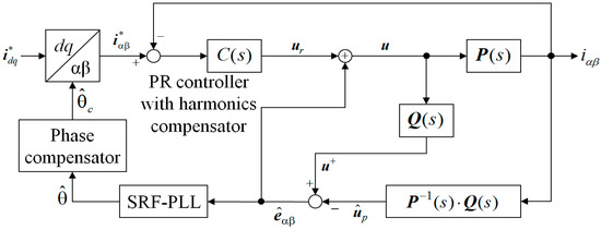
Figure 2.
Overall block diagram for the proposed voltage-sensorless control scheme.
From Equation (7), the disturbed control input can be calculated as follows:
with in Equation (6), the disturbed control input can be expressed as
Theoretically, can be calculated from the output if the system inverse model is realizable. However, because is not proper in general, a stable filter such as a low pass filter (LPF) is required in the implementation of the DOB in order that is proper.
Selecting as the first-order LPF, the disturbed system input is now modified to the filtered value as follows:
Considering the first-order LPF and Equation (8), the state space expression for the output of the transfer matrix is obtained as follows [26]:
where , , the symbol “^” denotes the estimated quantities, is the state of the first-order LPF , is the output of the transfer matrix , and and are the filter parameters, respectively. In Equation (12), the output corresponds to the filtered estimate of , which is determined by processing the output with the transfer matrix as in Equation (10).
Similarly, the same first-order LPF is needed to process the known control input . With the same transfer matrix in Equation (10), the state space representation can be expressed as follows:
where is the state of the LPF and denotes the output of the LPF. The output represents the filtered estimate of the known control input . Since two filtered estimates for and were obtained, the estimated disturbance that is the grid voltages in the stationary frame can be finally calculated as:
4. Proposed Voltage-Sensorless Control of a Grid Connected Inverter
In this section, the proposed voltage-sensorless control scheme which estimates the phase angle of the grid voltage is explained using Figure 2. The q-axis and d-axis current references are first transformed into the stationary values using the estimated phase angle. Using the processes described in Section 2, the PR current controller is designed for a grid connected inverter in the stationary reference frame. At the same time, the grid voltages are estimated through the DOB by comparing the reference voltages with the current information processed with the system inverse model. The estimated grid voltage in Equation (15), which is the output of the DOB, is used to compose the reference voltage signal as well as to generate the phase angle through the synchronous reference frame PLL (SRF-PLL).
However, due to the LPF used in the implementation of the DOB, the estimated grid voltage has some phase delay from the actual grid voltage . Such a phase delay is caused by the limits of the DOB, which generally depends on the bandwidth of the LPF. Fortunately, the PR current controller with the feedforward of the estimated grid voltage does not deteriorate the current control quality severely even if the estimated grid voltage has small phase delay. Moreover, the frequency variation is not significant in most grids. Thus, the phase angle determined from the estimated grid voltage with the phase delay needs to be compensated.
From the LPF in Equation (11), the transfer function of the first element can be obtained as follows:
From Equation (16), the phase delay at the grid frequency introduced by the LPF can be simply calculated as follows:
where denotes the grid angular frequency and denotes the phase delay due to the LPF in DOB. Let denote the phase angle determined from the estimated grid voltage . Because has the phase delay from , the phase angle of the actual grid voltage can be simply obtained by adding the delay angle as follows:
where is the compensated phase angle which completely reconstructs the phase angle of the actual grid voltage. This phase angle is used to transform the current references into the stationary values in Figure 2.
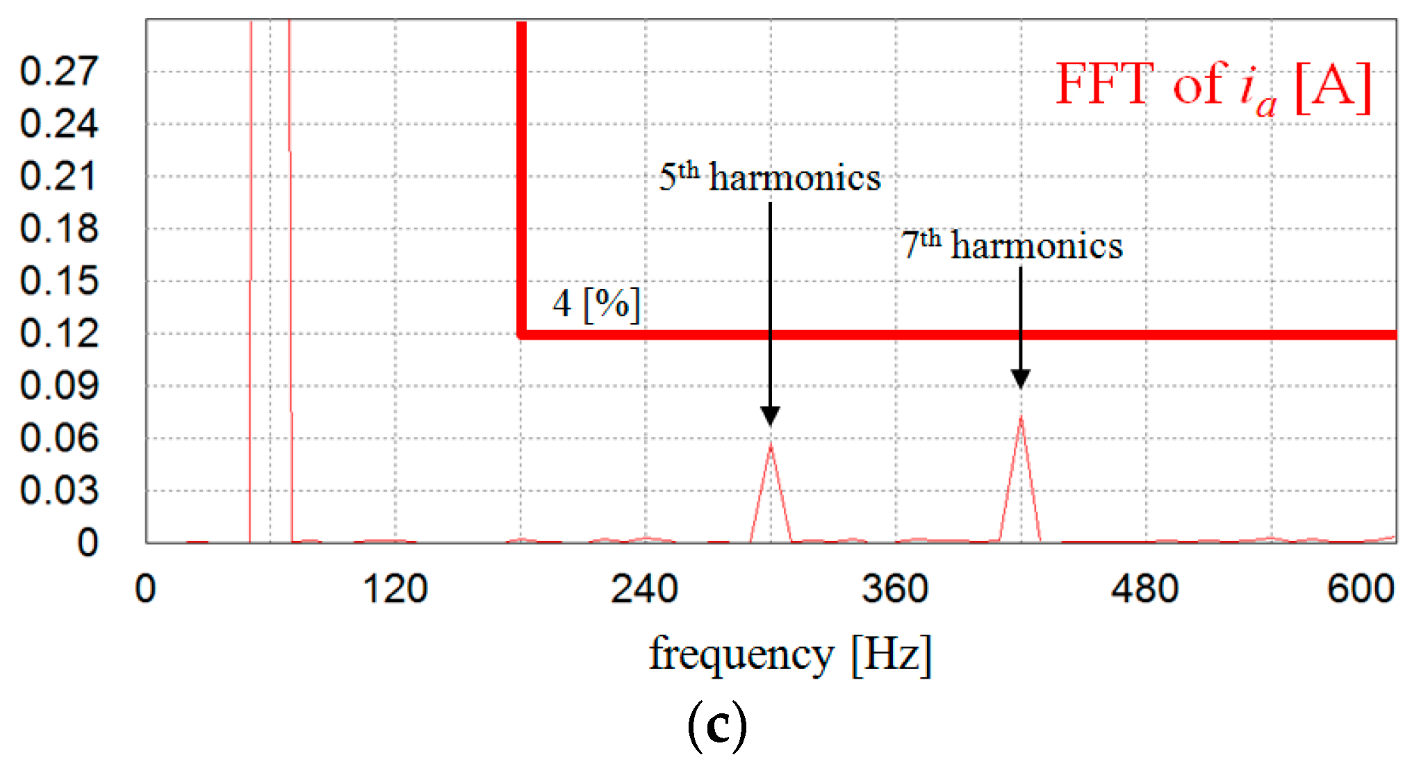
According to the harmonic limit on IEEE Standard 519-1992, the fifth- and the seventh-order harmonics on the inverter output currents should be less than 4% [27]. To ensure the robustness against harmonic distortions in the grid voltages, the harmonic regulators are incorporated in addition to Equation (4). Then, the reference voltages of the proposed controller are obtained using the estimated grid voltage as follows:
5. Simulations and Experimental Results
To prove the feasibility of the proposed voltage-sensorless control scheme for a grid connected inverter, the simulations and experimental results are presented. The simulations are carried out using the PSIM Software (Powersim, Rockville, MD, USA).
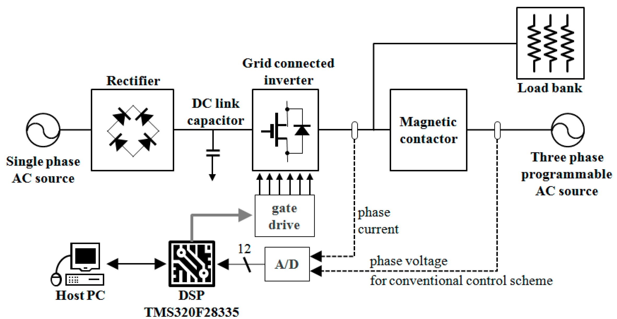
Figure 3 shows the configuration of the overall system. The entire system consists of a DC source, a grid connected inverter, a DSP based controller, and three-phase programmable AC power source that can emulate the ideal grid as well as distorted or unbalanced grid. The whole control algorithm is implemented using DSP TMS320F28335 for 2 kVA prototype three-phase grid-connected inverter [25]. The sampling period is chosen as 100 μs both in the simulations and experiments, which yields the switching frequency of 10 kHz. The intelligent power module is employed for three-phase grid-connected inverter. The inverter phase currents are detected by the Hall-effect devices and are converted through internal 12-bit A/D converters, where the resolution of current is 18/211 A.
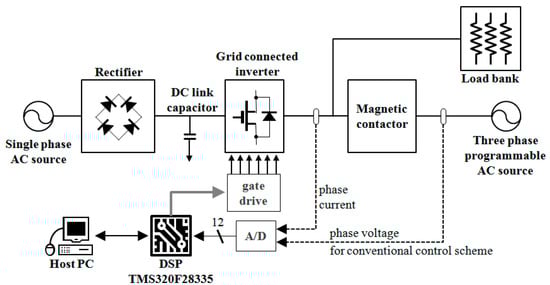
Figure 3.
Configuration of the overall system.
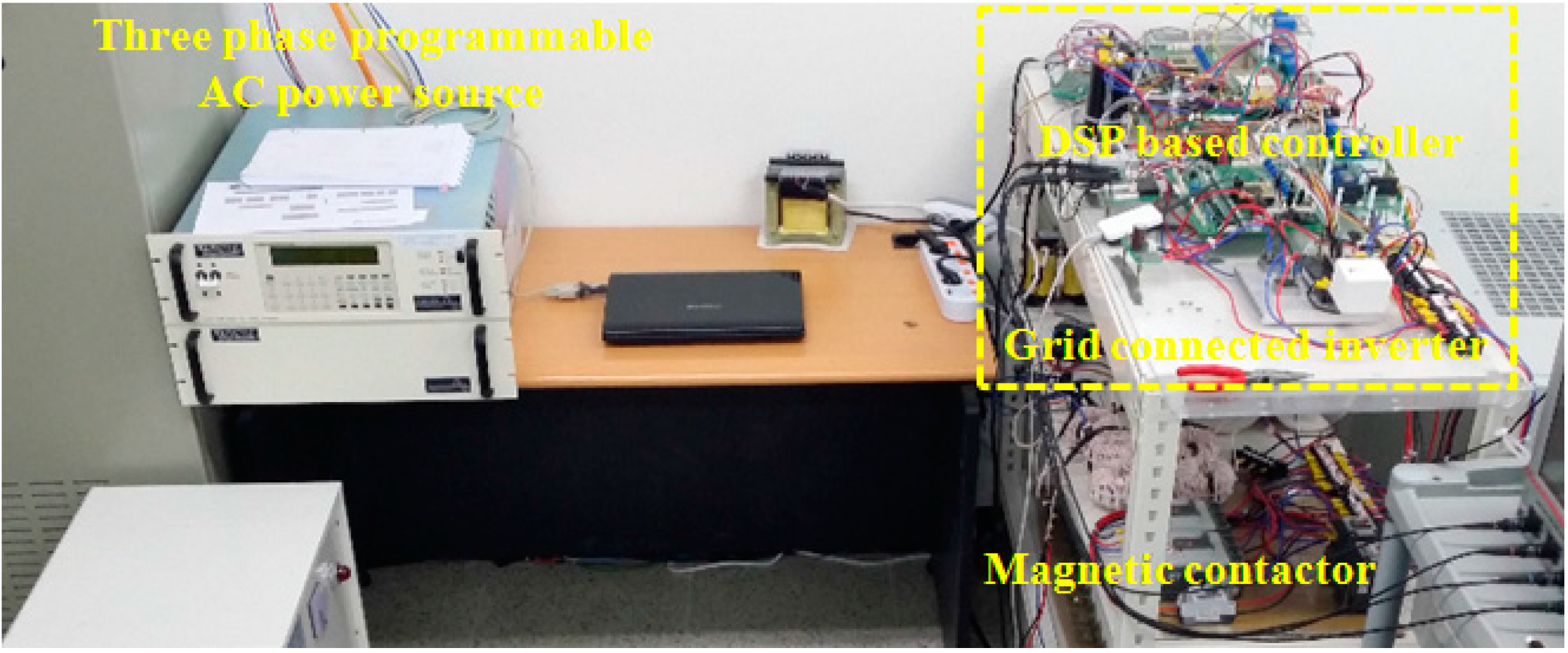
Figure 4 shows the experimental test setup consisting of a DSP based controller, three-phase grid connected inverter, magnetic contactor (MC) for grid connection, and three-phase programmable AC power source. The system parameters of the experimental system are listed in Table 1.
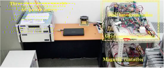
Figure 4.
Experimental test setup.

Table 1.
Specifications of a grid connected inverter.
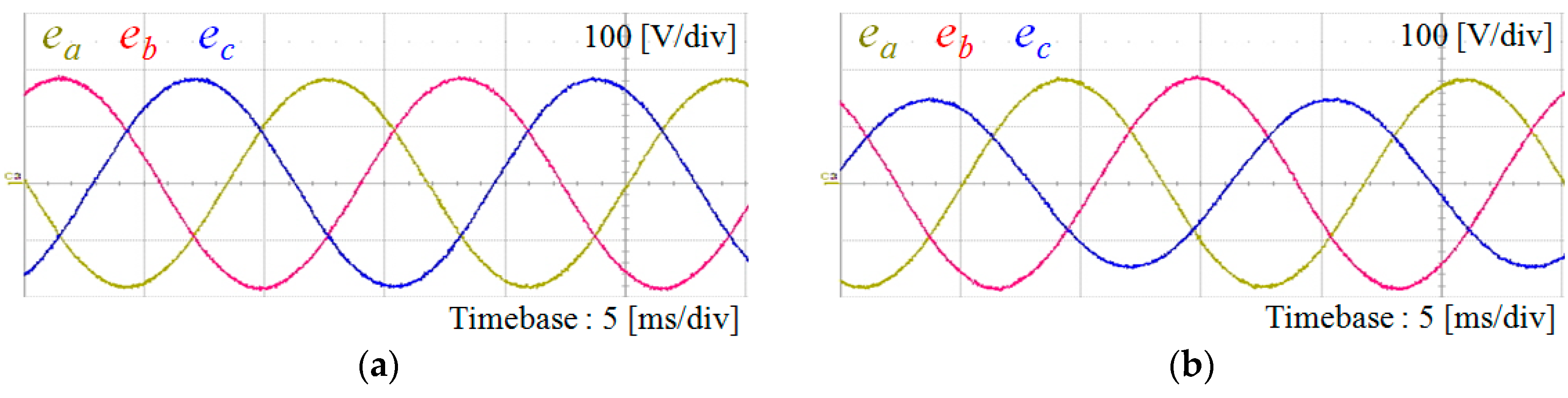
Figure 5 shows various grid voltages used for test purpose, which are generated by three-phase programmable AC power source. Figure 5a represents the ideal grid voltages in which the frequency is 60 Hz and the line-to-line voltage is 220 V in root-mean-square (RMS). Figure 5b shows three-phase unbalanced grid voltages with 20% magnitude reduction in c-phase. Figure 5c shows the harmonic distorted grid voltages including 5% of the fifth- and seventh-order harmonics, respectively.
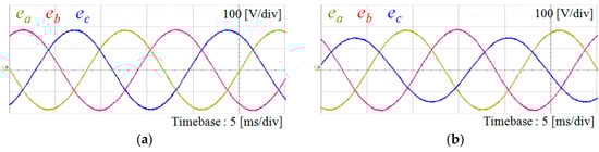
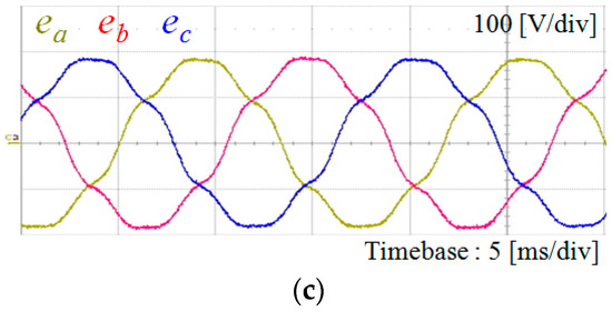
Figure 5.
Grid voltages under various conditions. (a) Ideal grid voltages; (b) three-phase unbalanced grid voltages; and (c) harmonic distorted grid voltages.
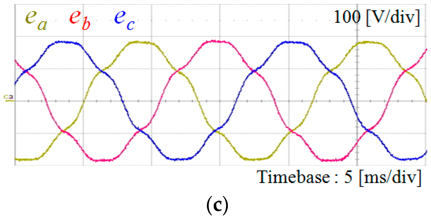
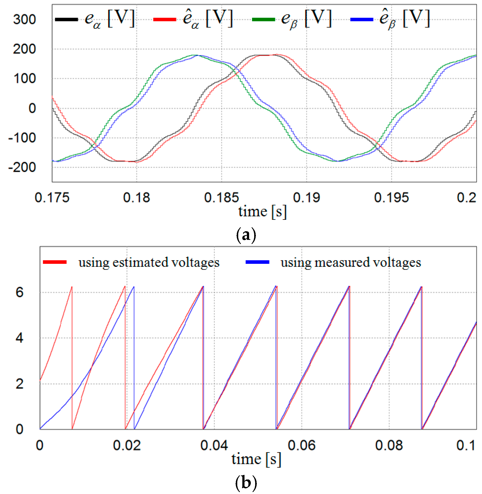
Figure 6 shows the simulation results under the ideal grid condition to illustrate the estimation performance for the grid voltages and phase angle using DOB. The grid voltages are estimated in the stationary frame using Equation (15) as represented in Figure 2. As is clearly observed from Figure 6a, even if the proposed scheme estimates the stationary q-axis and d-axis grid voltages well, the estimated voltages have small phase delay from the actual grid voltage. This result was expected because two filtered signals by the LPF were employed to obtain the estimates for the grid voltage in Equation (15). However, this phase delay can be easily calculated. As a result, the phase-lead compensation to reconstruct the phase angle of actual grid voltage can be simply accomplished by Equation (18). Figure 6b shows the PLL results using the estimated grid voltages with phase-lead compensation. For comparison, two PLL results are shown where one is obtained using the measured voltages and the other using the estimated voltages. It is clearly shown that two waveforms well coincide with each other within three periods, which proves the validity of the proposed grid voltage estimation scheme.
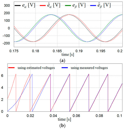
Figure 6.
Estimation of grid voltages and phase angle using DOB under the ideal grid condition. (a) Measured and estimated stationary q-axis and d-axis grid voltages; and (b) phase-locked loop (PLL) results using the measured voltages and estimated voltages at start-up.
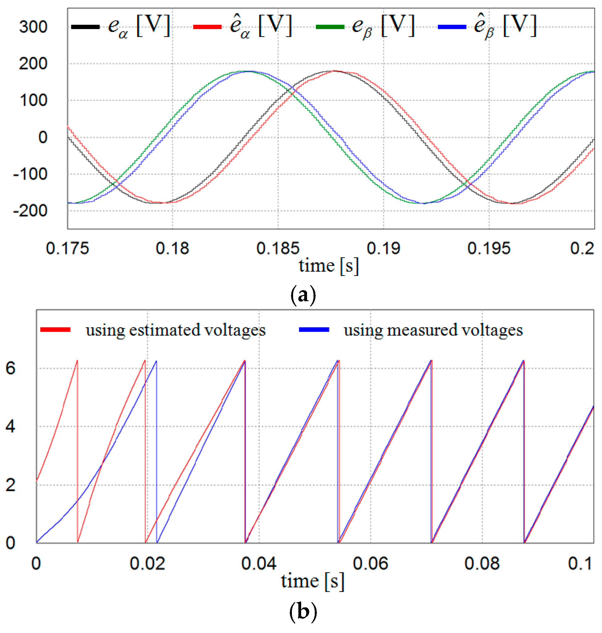
Figure 7 shows the estimation performance of the grid voltages and phase angle using the proposed DOB based scheme when three-phase grid voltages are in unbalanced condition as shown in Figure 5b. Even in this case, the DOB still works successfully except for small phase delay as expected. Similarly, the exact phase angle of the grid voltages can be determined by the proposed scheme in a few cycles.
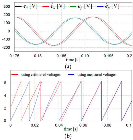
Figure 7.
Estimation of grid voltages and phase angle using DOB under unbalanced grid condition. (a) Measured and estimated stationary q-axis and d-axis grid voltages; and (b) PLL results using measured voltages and estimated voltages at start-up.
Figure 8 shows the simulation results for the estimation performance of the grid voltages and phase angle using the proposed scheme when the grid voltages have harmonic distortion as represented in Figure 5c. Despite the harmonic distortion, the proposed scheme shows an excellent performance in the estimation of the grid voltages as well as in the determination of the phase angle.
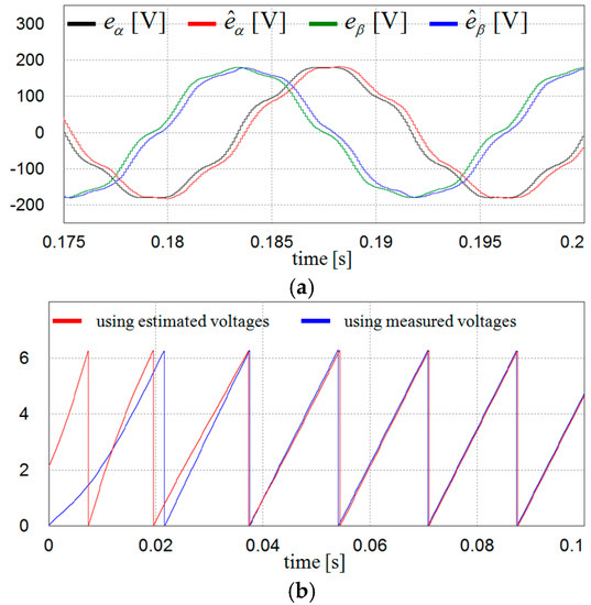
Figure 8.
Estimation of grid voltages and phase angle using DOB under harmonic distorted grid condition. (a) Measured and estimated stationary q-axis and d-axis grid voltages; and (b) PLL results using measured voltages and estimated voltages at start-up.
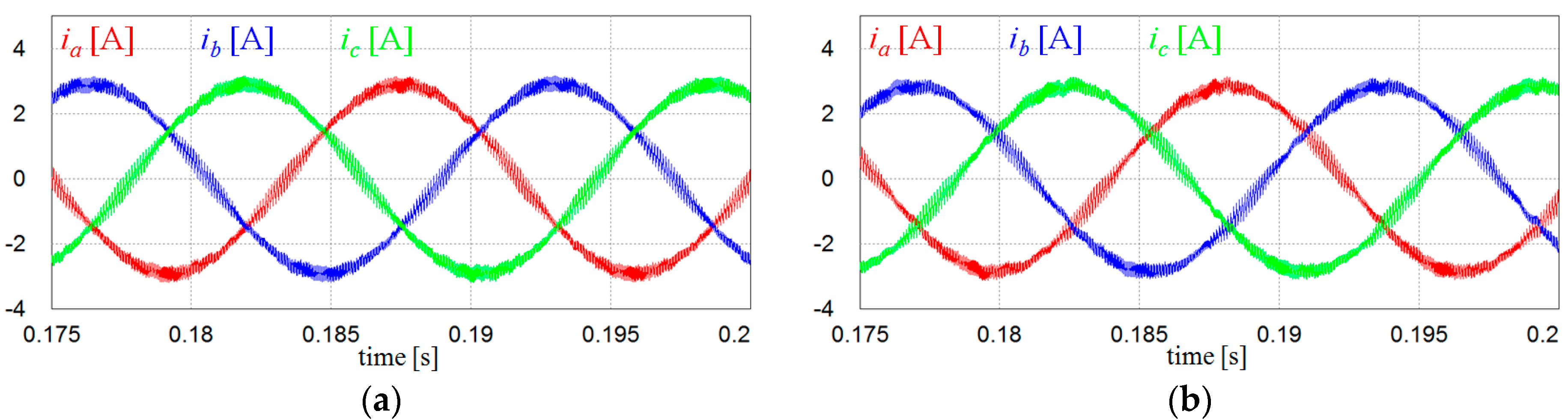
To verify the feasibility of the proposed scheme, Figure 9 illustrates the comparative simulation results for the inverter output currents under the ideal grid condition between the conventional scheme with voltage measurements and the proposed voltage-sensorless control scheme. It is obvious from these figures that the control performance of the proposed scheme is comparable to the case with voltage measurements.
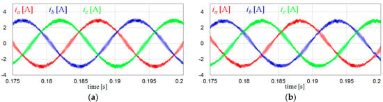
Figure 9.
Comparison of inverter output currents under the ideal grid condition. (a) Inverter output currents with voltage measurements; and (b) inverter output currents with the proposed voltage-sensorless control.
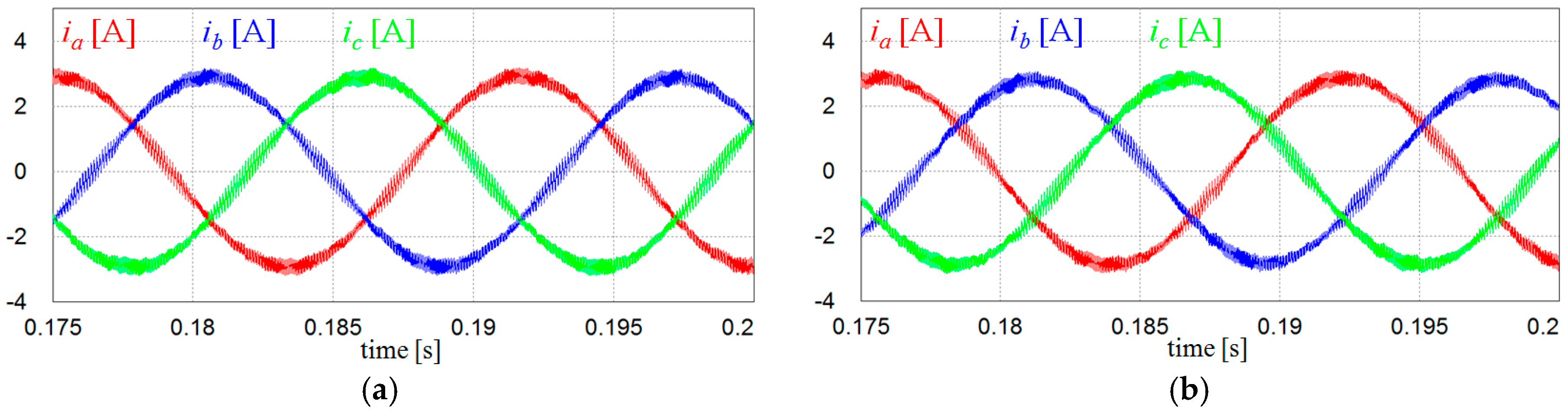
Figure 10 represents the comparative simulation results under three-phase unbalanced grid voltages as in Figure 5b for the schemes with and without the voltage sensors. It is clearly shown that both schemes yield similar current waveforms, which proves that the proposed scheme works well even in this condition.
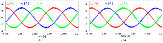
Figure 10.
Comparison of inverter output currents under unbalanced grid condition. (a) Inverter output currents with voltage measurements; and (b) inverter output currents with the proposed voltage-sensorless control.
Figure 11 shows the comparative simulation results under the harmonic distorted grid condition as in Figure 5c for the schemes with and without the voltage sensors. Similar to the previous simulations, Figure 11a,b represents the inverter currents for the conventional and proposed scheme. On the other hand, Figure 11c shows the fast Fourier transform (FFT) result for a-phase current waveform in Figure 11b together with the harmonic limits on IEEE Standard 519-1992. In this case, both the current waveform and the power quality are slightly degraded in the proposed control scheme as compared with the conventional scheme due to the bandwidth limit of the LPF used in DOB. However, the harmonics on inverter currents are effectively maintained within the harmonic limits specified on IEEE Standard 519-1992 as in Figure 11c.
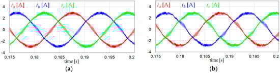
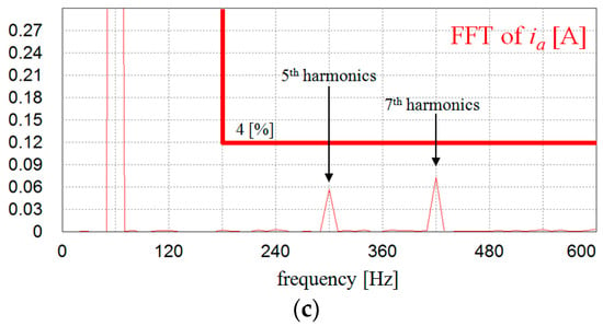
Figure 11.
Comparison of inverter output currents under harmonic distorted grid condition. (a) Inverter output currents with voltage measurements; (b) inverter output currents with the proposed voltage-sensorless control; and (c) fast Fourier transform (FFT) result for a-phase current in (b).
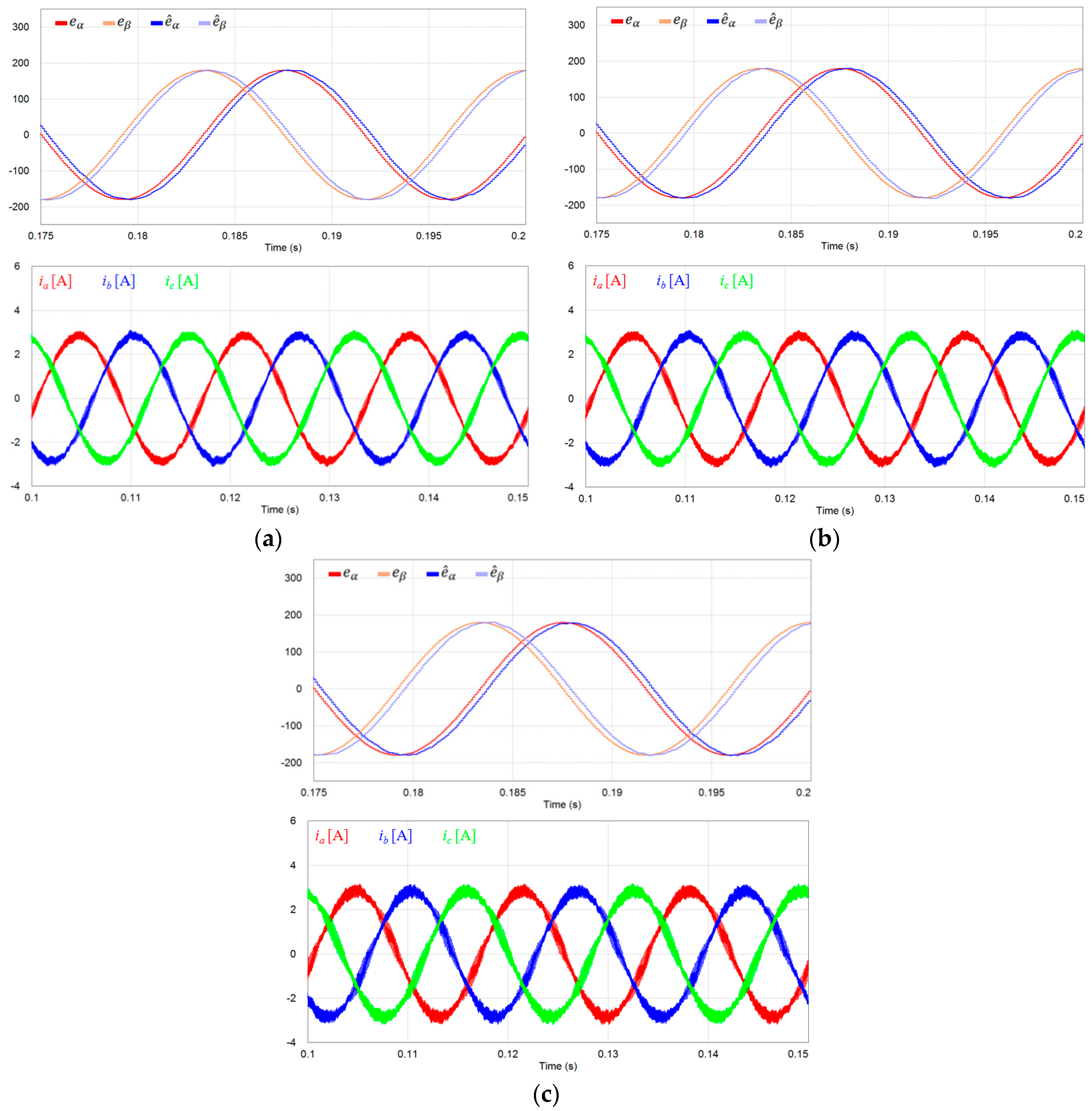
Figure 12 shows the estimation performance of grid voltages and corresponding inverter output current waveforms under different inductance variations. Even though the magnitude of current ripple is varied due to the different inductance values, the estimation performance of grid voltages is not affected by such a variation, which well proves the robustness of the proposed estimation algorithm.
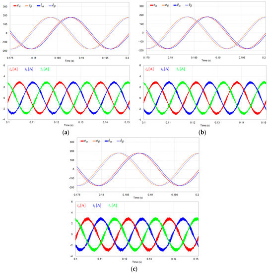
Figure 12.
Estimation of grid voltages and inverter output currents under inductance variation. (a) +20% variation; (b) +10% variation; and (c) −20% variation.
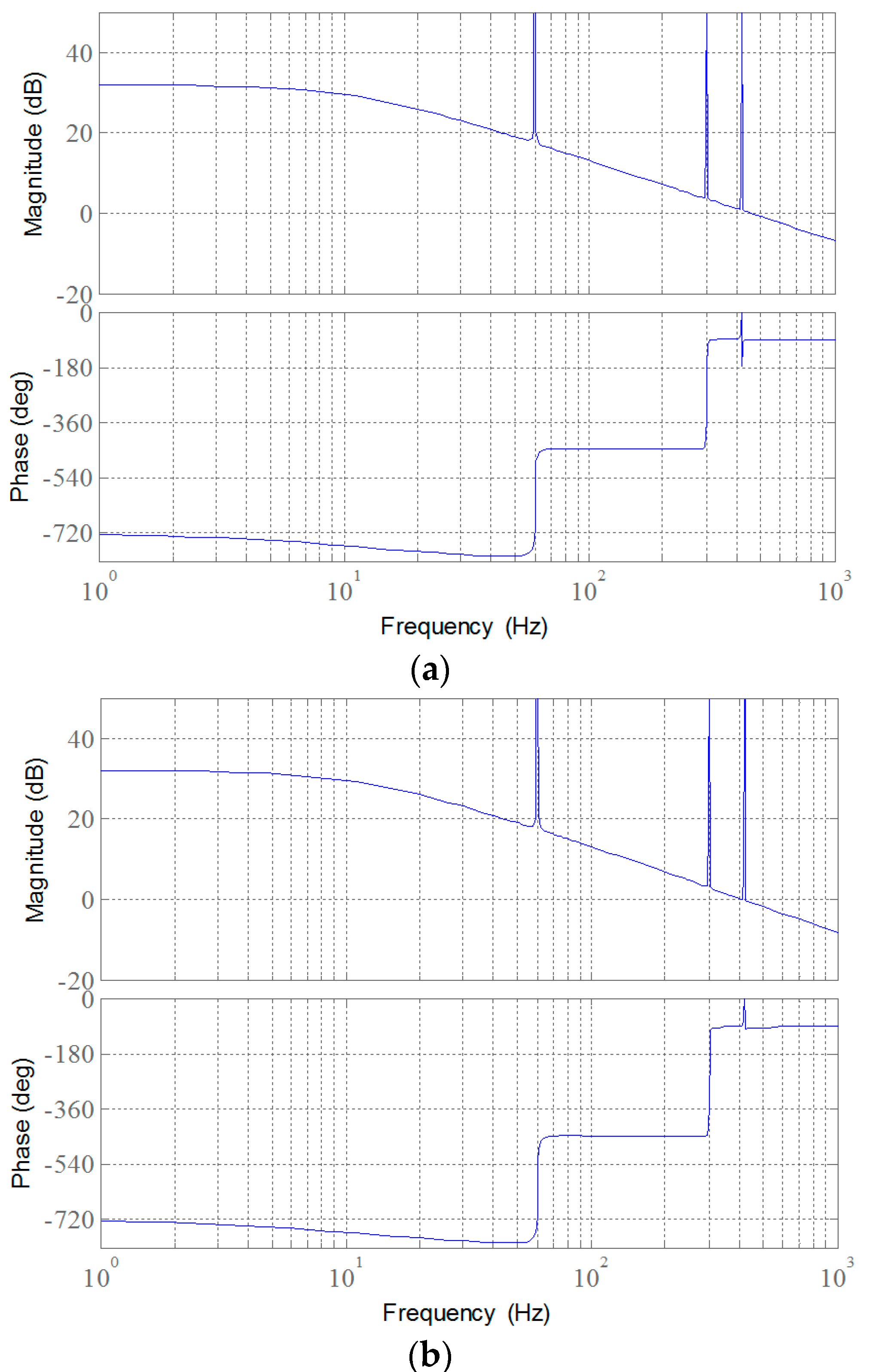
Figure 13 shows the frequency responses for the open-loop transfer function of Figure 2 when the voltage feed-forward is considered under the nominal value of inductance and +20% variation of inductance, respectively. Despite the inductance variation, the frequency responses remain similar and both the frequency responses satisfy the stability criterion. In addition, the phase compensation does not affect the system stability because it is only used to change the phase angle, and thus, the reference current in the stationary frame.
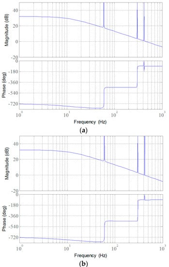
Figure 13.
Frequency responses for the open-loop transfer function under inductance variation. (a) Nominal value of inductance; and (b) +20% variation.
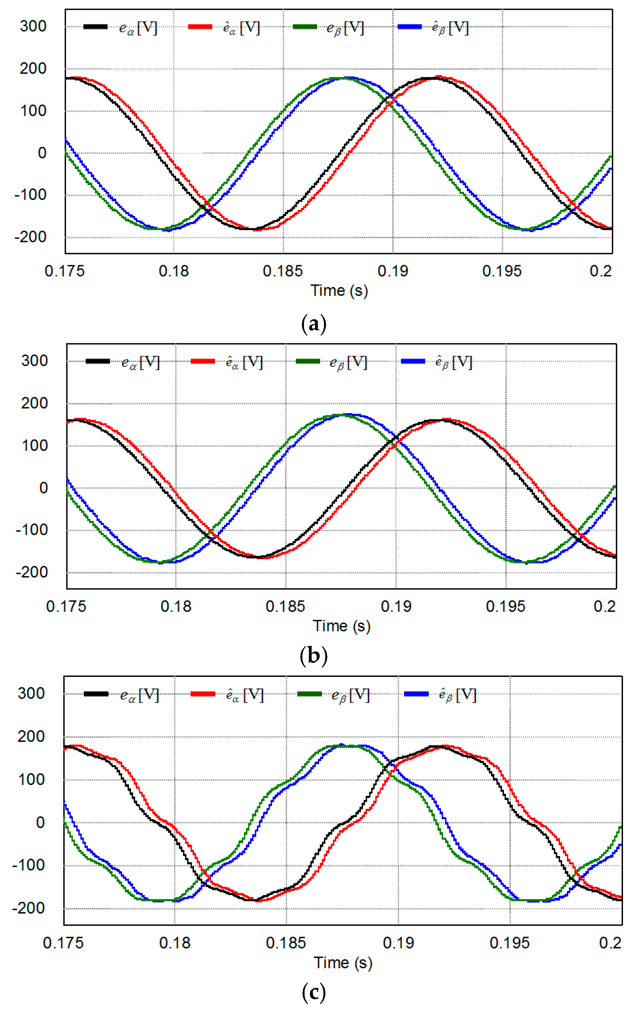
Figure 14 shows the estimation performance of grid voltages using the conventional linear Luenberger type disturbance observer under the ideal grid voltages, unbalanced grid voltages, and harmonic distorted grid voltages, respectively. The estimation performance of grid voltages is more or less similar to that of the proposed scheme depending on the observer error dynamics. This scheme also has the limitation that sinusoidally varying signals have to be tracked, and, thus, the current control performance will be much degraded without proper phase compensation.
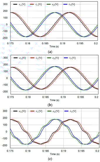
Figure 14.
Estimation of grid voltages using the conventional linear Luenberger type disturbance observer. (a) Under the ideal grid voltages; (b) under unbalanced grid voltages; and (c) under harmonic distorted grid voltages.
To validate the actual availability of the proposed scheme, the experiments are carried out using the equipment depicted in Figure 3 and Figure 4.
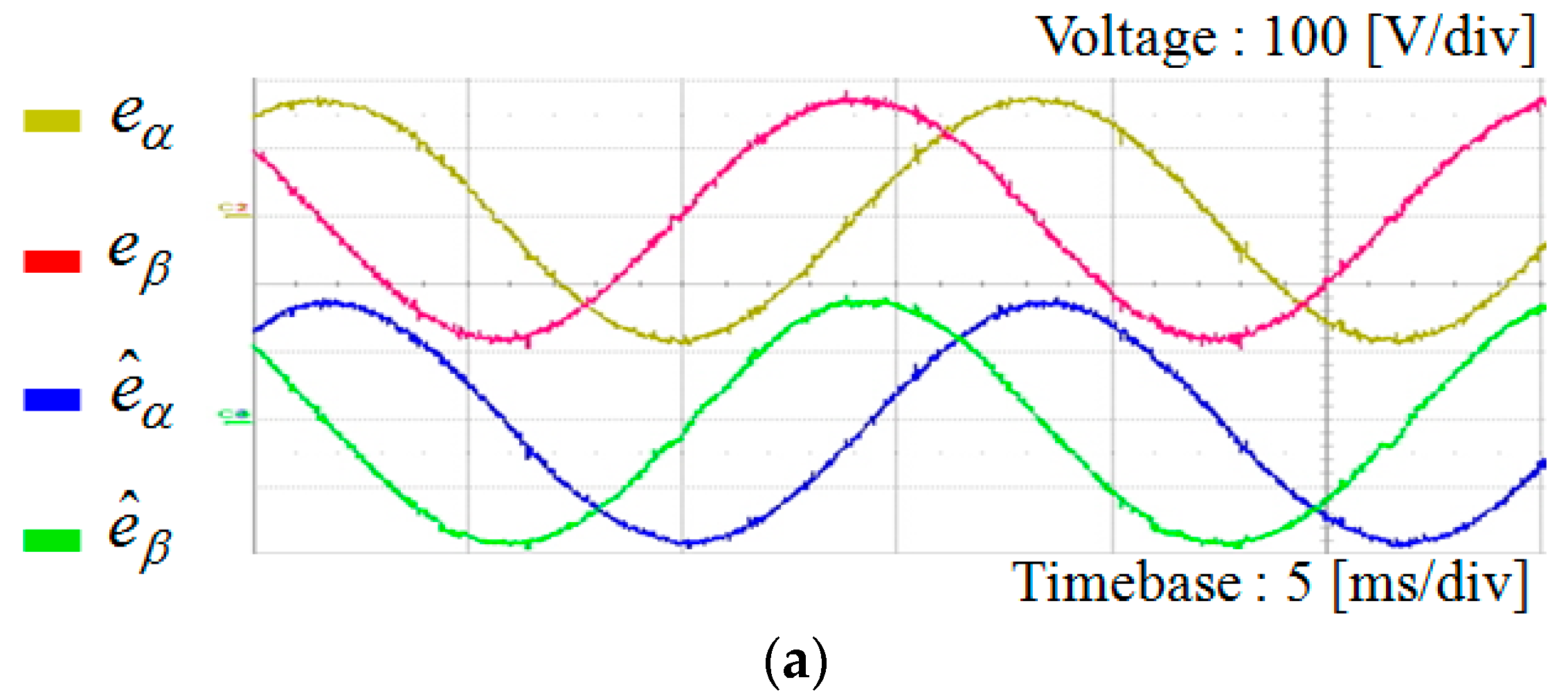
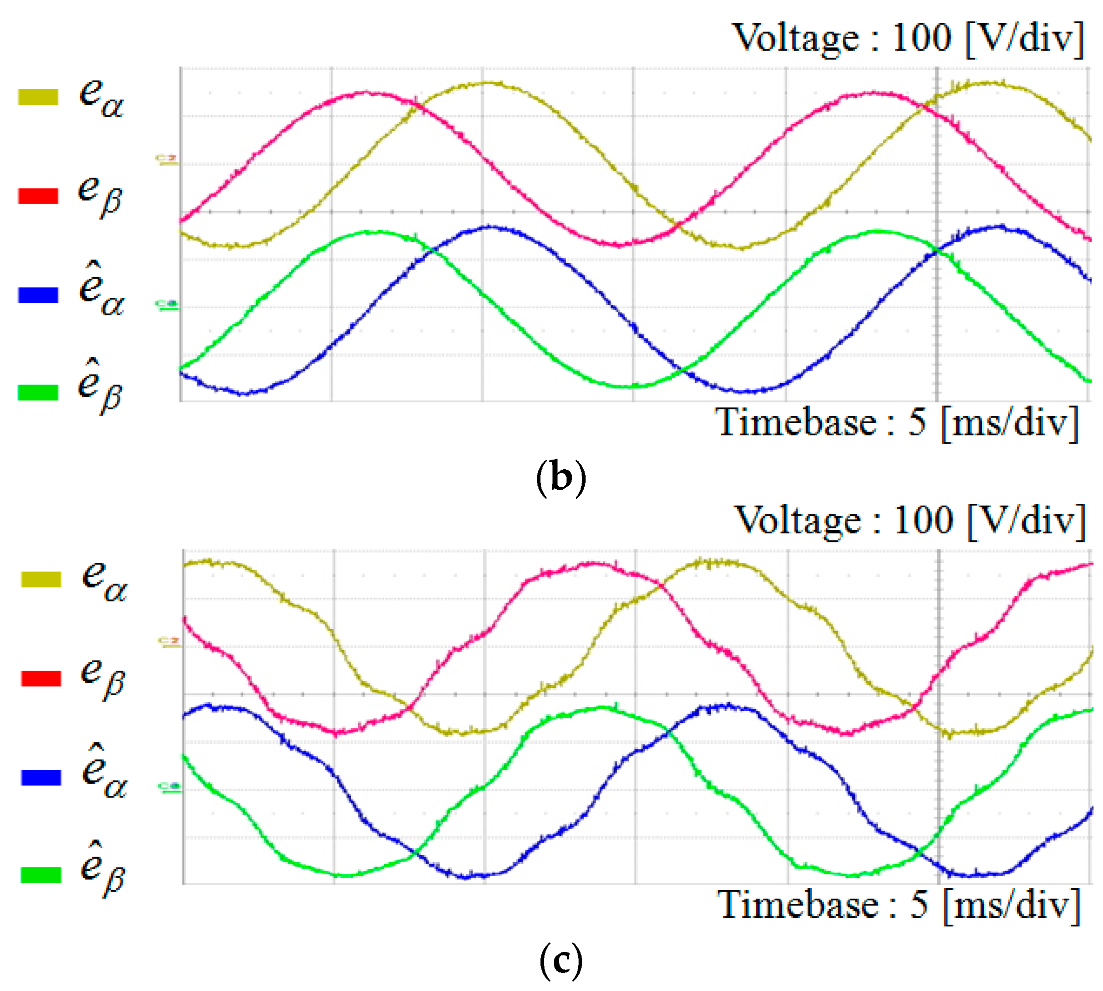
Figure 15 shows the experimental results for the DOB based estimating performance of grid voltages under three different grid conditions as presented in Figure 5. The experimental results accord well with the simulation results in Figure 6, Figure 7 and Figure 8, yielding the grid voltage information in a reasonable accuracy.
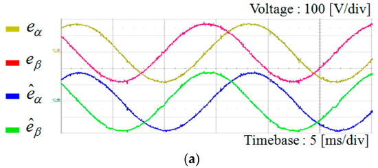
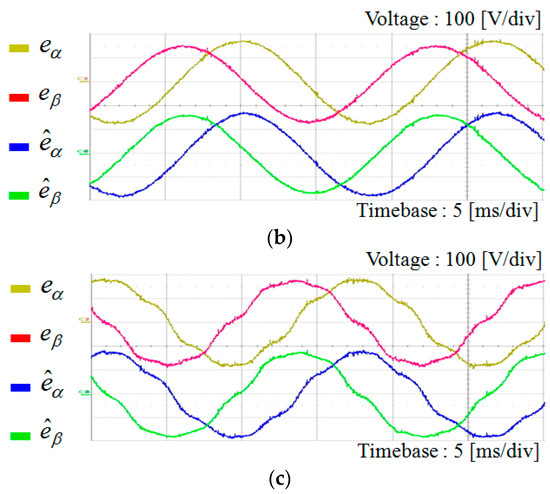
Figure 15.
Experimental results for the estimation of grid voltages using DOB. (a) Under the ideal grid voltages; (b) under unbalanced grid voltages; and (c) under harmonic distorted grid voltages.
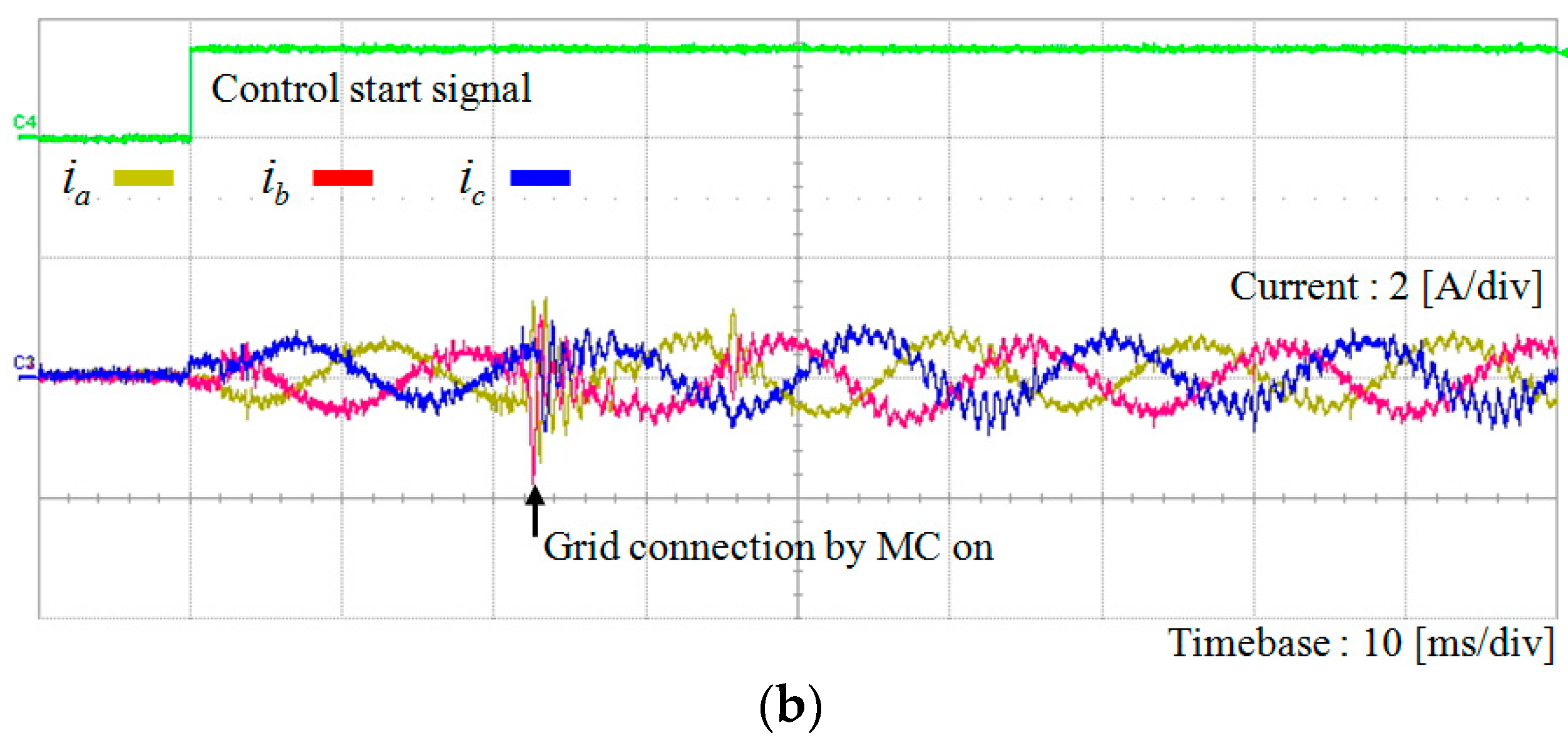
Figure 16 shows the experimental results for the phase angle estimation and transient current responses of the proposed voltage-sensorless control scheme at start-up under the ideal grid voltages in Figure 5a. In the initial stage, the current references are set to small value (0.5 A) to prevent large abrupt currents caused by the inaccurate phase angle information in the absence of the grid voltage estimation. Figure 16a represents the waveforms of the measured a-phase grid voltage and phase angle estimation. In this figure, denotes the phase angle obtained using the measured voltages, which is referred as the real phase angle of grid voltages and used for only comparison purpose. On the other hand, denotes the phase angle obtained using the estimated voltages with phase lead compensation, which is the phase angle determined by the proposed scheme. While the connection signal for the MC is given with the “control start signal” as shown in Figure 16a, it requires about 20 ms to operate. The connection instant is indicated by the “grid connection by MC on”. As soon as the MC is closed and the inverter is connected to grid, the DOB estimates the grid voltages properly. As a result, the proposed voltage-sensorless scheme detects the exact phase angle of grid voltages within two cycles. Figure 16b represents three-phase inverter current waveforms with the “control start signal” during the start-up process. Similarly, it takes about 20 ms for MC to connect. As soon as MC is connected, the inverter is in grid connected mode. From that instant, both the control input and system output signals are available for the DOB for the estimation of grid voltage and phase angle. Even though some oscillatory currents are observed due to dynamic characteristics of the DOB after MC connection to grid, such a transient behavior disappears in few milliseconds. As a result, despite the uncertainty due to the absence of voltage sensors, the proposed scheme stabilizes the system operation rapidly without giving a harmful damage to system.
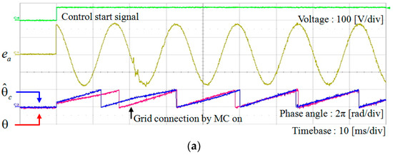
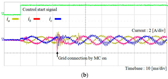
Figure 16.
Phase angle estimation and transient current responses of the proposed voltage-sensorless control scheme at start-up. (a) Waveforms of the measured a-phase grid voltage and phase angle estimation (: PLL result using the measured voltages, : PLL result using the estimated voltages with compensation); and (b) inverter output currents at start-up.
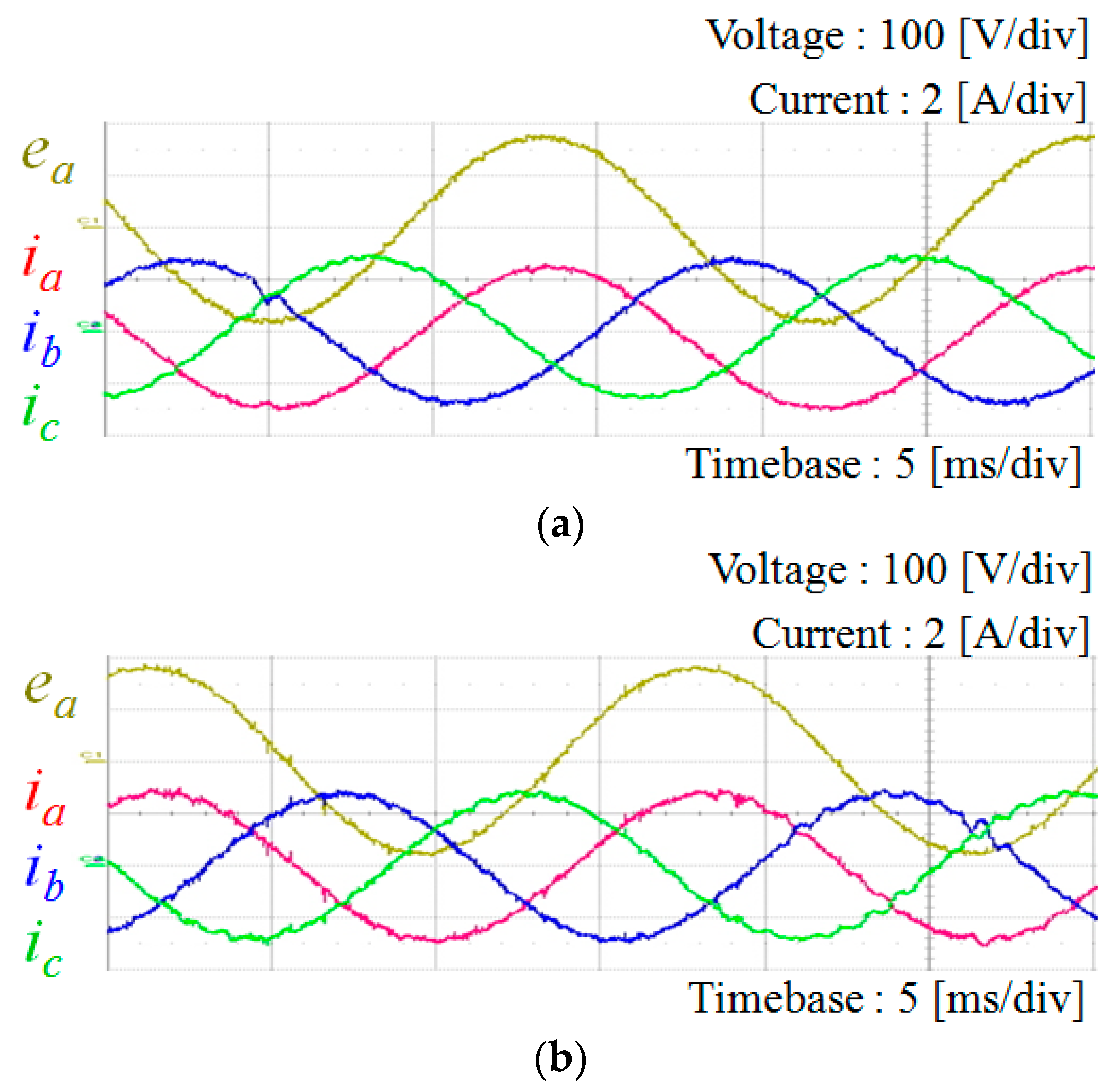
Figure 17 shows the comparative experimental results for the schemes with and without the voltage sensors when the grid voltages are in ideal condition as shown in Figure 5a. The grid voltages are estimated in the stationary frame as (15). These estimated grid voltages are used to generate the phase angle through the SRF-PLL with phase lead compensation as explained in Figure 2. As expected, the current waveforms are quite similar for both the cases, which is well coincident with the simulation results in Figure 9. This confirms the effectiveness of the proposed voltage-sensorless control scheme in an experimental way.
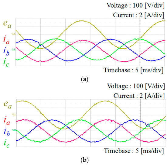
Figure 17.
Comparative experimental results for inverter output currents under the ideal grid condition. (a) With the conventional PR control with voltage measurements; and (b) with the proposed voltage-sensorless control.
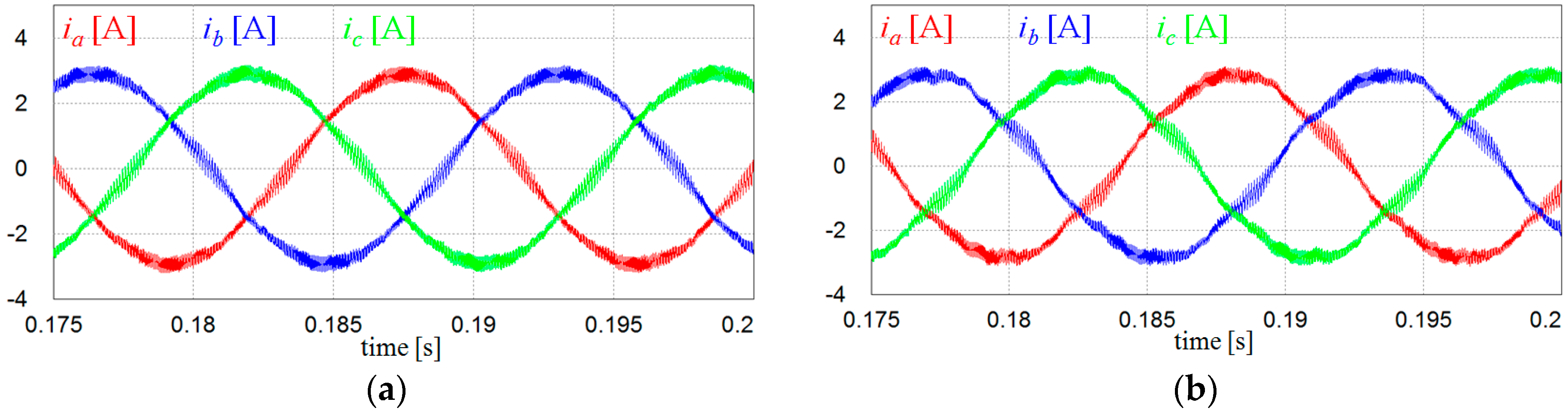
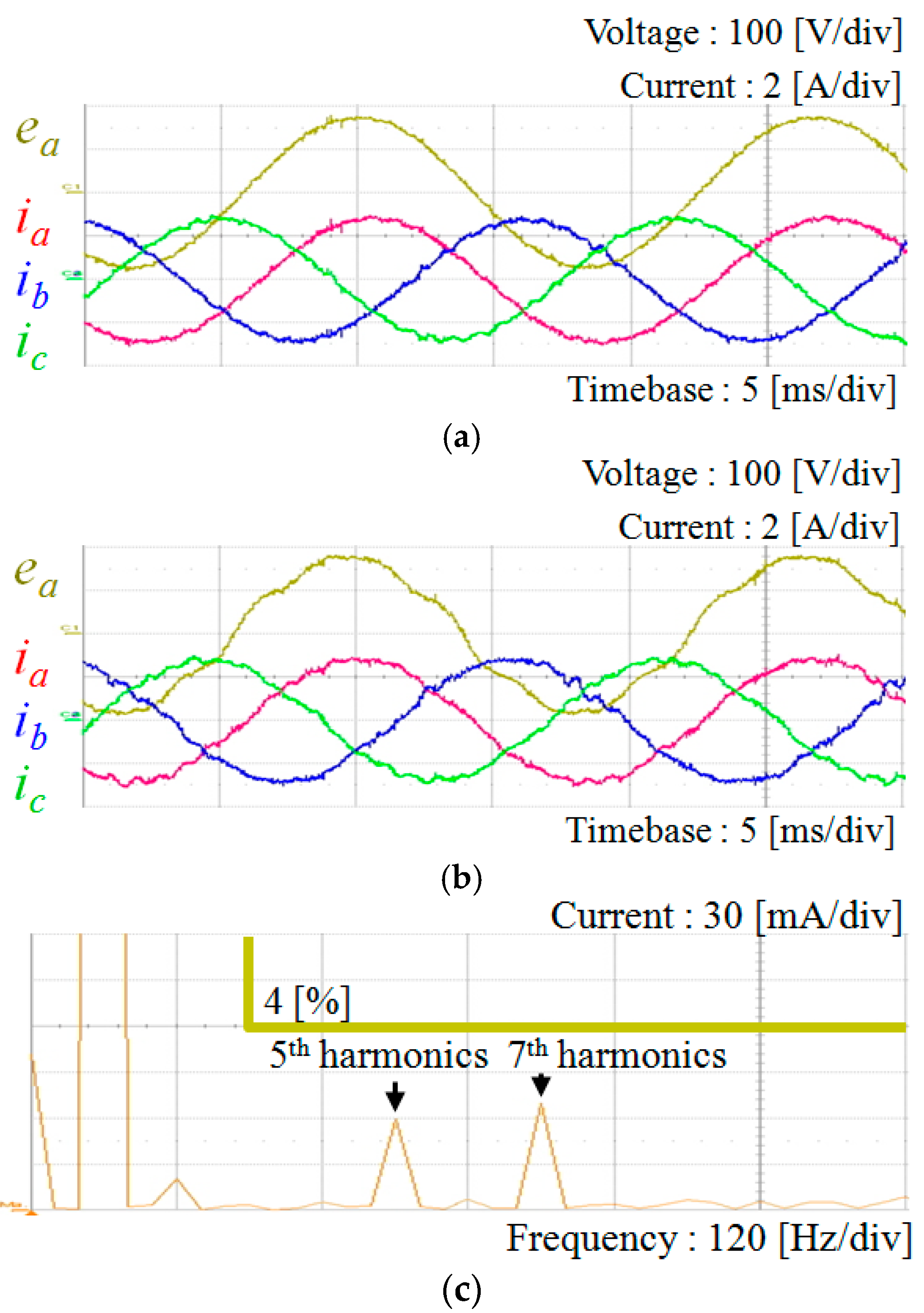
Figure 18 represents the experimental results for the proposed voltage-sensorless control scheme of a grid connected inverter when the grid voltages are unbalanced or harmonic distorted as shown in Figure 5b,c. Figure 18a,b represents three-phase inverter current waveforms under unbalanced grid voltages and under harmonic distorted grid voltages, respectively. Generally, the harmonics on grid voltages directly influence on the current control performance, reducing the power quality of DG system. Even though the current waveforms are slightly distorted due to the harmonic distortion in grid voltages in Figure 18b, the current harmonics are within the limits specified on IEEE Standard 519-1992 as illustrated in Figure 18c, which proves that the proposed voltage-sensorless scheme still works even under the harmonic distorted grid.
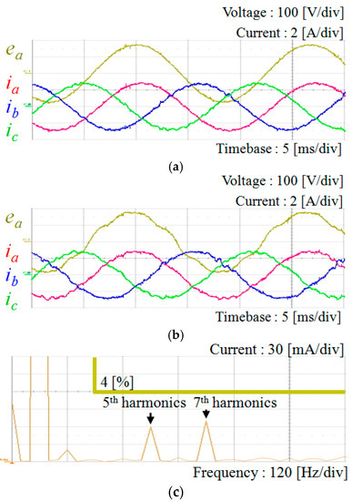
Figure 18.
Experimental results for inverter output currents of the proposed voltage-sensorless control scheme under distorted grid condition. (a) Under unbalanced grid voltages; (b) under harmonic distorted grid voltages; and (c) FFT result for a-phase current in (b).
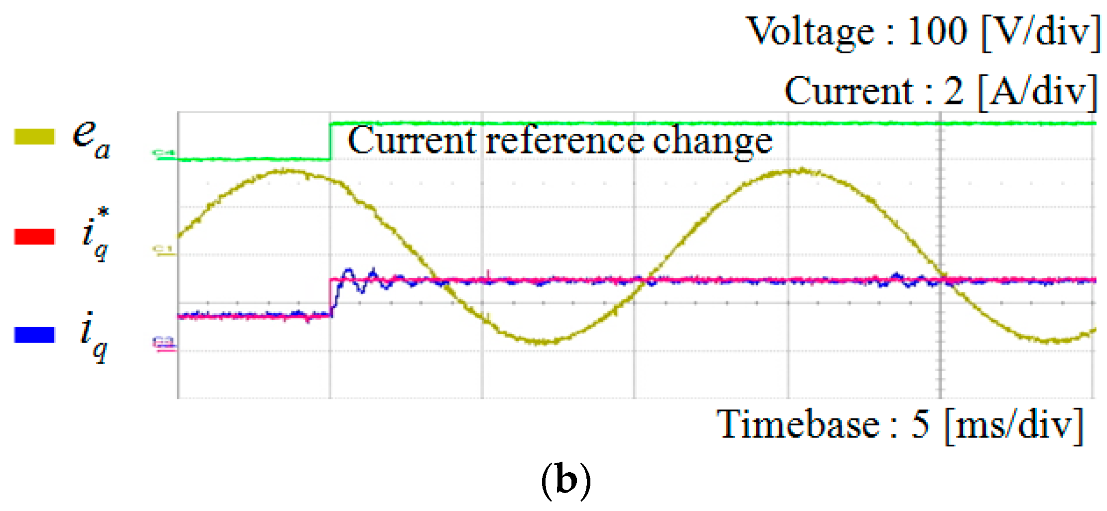
To demonstrate the transient performance of the proposed scheme, Figure 19 shows the experimental results under the step change in the q-axis current reference from 1.5 A to 3 A. Figure 19a shows a-phase and b-phase currents, and Figure 19b shows the q-axis current. As shown in these figures, despite a slight oscillation depending on the choice of resonant gains, the currents are controlled to the reference immediately. From these results, it is confirmed that the proposed scheme operates stably during transient periods.
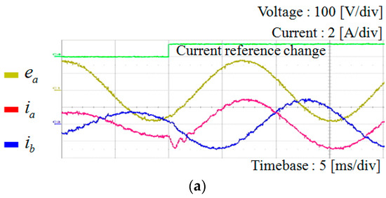
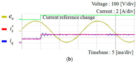
Figure 19.
Experimental results of the proposed control scheme under the step change in current reference. (a) a-phase and b-phase current responses; and (b) q-axis current response.
6. Conclusions
To enhance the economic feasibility in DG systems without the loss of reliability, this paper presents a voltage-sensorless control scheme for a grid connected inverter using DOB. A grid connected inverter usually requires voltage measurements to detect the correct phase angle of the grid voltages. To obtain the grid voltage information without using the voltage sensors, the proposed scheme employs a DOB based technique to estimate the grid voltage from the current measurements and reference signals. By using the proposed DOB based estimation with a phase lead compensation, the phase angle of grid voltages can be completely restored even if the phase angle of grid is initially unknown. The proposed scheme mainly consists of two parts that are a control design of grid connected inverter based on the PR controller and the estimator design for the grid voltages as well as the phase angle. The proposed scheme is simple and straightforward. In addition, it does not require any additional hardware. Even in the initial stage, the proposed scheme does not cause any damage to system due to the uncertainty in phase angle. To verify the feasibility of the proposed voltage-sensorless control scheme, a 2 kVA prototype grid connected inverter has been constructed using the DSP TMS320F28335. Through the comparative simulations and experiments, it has been validated that the proposed scheme works effectively even under the uncertain grid such as the imbalance and harmonic distortion.
Acknowledgments
This research was supported by Basic Science Research Program through the National Research Foundation of Korea (NRF) funded by the Ministry of Education (NRF-2016R1D1A1B03930975). This work was also supported by the Human Resources Development of the Korea Institute of Energy Technology Evaluation and Planning (KETEP) grant funded by the Korea government Ministry of Trade, Industry & Energy (NO. 20154030200720).
Author Contributions
Hyun-Sou Kim and Kyeong-Hwa Kim conceived the main concept of the control structure and developed the entire system. Hyun-Sou Kim carried out the research and analyzed the numerical data with the guidance from Kyeong-Hwa Kim. Hyun-Sou Kim and Kyeong-Hwa Kim collaborated to prepare the manuscript.
Conflicts of Interest
The authors declare no conflict of interest.
References
- Mohamed, Y.A.R.I.; Rahman, M.A.; Seethpathy, R. Robust line-voltage sensorless control and synchronization of LCL-filtered distributed generation inverters for high power quality grid connection. IEEE Trans. Power Electron. 2012, 27, 87–98. [Google Scholar] [CrossRef]
- Judewicz, M.G.; Gonzalez, S.A.; Echeverria, N.I.; Fischer, J.R.; Carrica, D. Generalized predictive current control (GPCC) for grid-tie three-phase inverters. IEEE Trans. Ind. Electron. 2016, 63, 4475–4484. [Google Scholar] [CrossRef]
- Wu, W.; Sun, Y.; Huang, M.; Wang, X.; Wang, H.; Blaabjerg, F.; Liserre, M.; Chung, H.S.H. A robust passive damping method for LLCL-filter-based grid-tied inverters to minimize the effect of grid harmonic voltages. IEEE Trans. Power. Electron. 2014, 29, 3279–3289. [Google Scholar] [CrossRef]
- Liserre, M.; Cardenas, R.; Molinas, M.; Rodriguez, J. Overview of multi-MW wind turbines and wind parks. IEEE Trans. Ind. Electron. 2011, 58, 1081–1095. [Google Scholar] [CrossRef]
- Wang, J.; Xu, D.; Wu, B.; Luo, Z. A low-cost rectifier topology for variable-speed high-power PMSG wind turbines. IEEE Trans. Power Electron. 2011, 26, 2192–2200. [Google Scholar] [CrossRef]
- Sosa, J.L.; Castilla, M.; Miret, J.; Matas, J.; Al-Turki, Y.A. Control strategy to maximize the power capability of PV three-phase inverters during voltage sags. IEEE Trans. Power Electron. 2016, 31, 3314–3323. [Google Scholar] [CrossRef]
- Lin, F.J.; Lu, K.C.; Ke, T.H.; Yang, B.H.; Chang, Y.R. Reactive power control of three-phase grid-connected PV system during grid faults using Takagi–Sugeno–Kang probabilistic fuzzy neural network control. IEEE Trans. Ind. Electron. 2015, 62, 5516–5528. [Google Scholar] [CrossRef]
- Yi, H.; Zhuo, F.; Wang, F.; Wang, Z. A digital hysteresis current controller for three-level neural-point-clamped inverter with mixed-levels and prediction-based sampling. IEEE Trans. Power Electron. 2016, 31, 3945–3957. [Google Scholar] [CrossRef]
- Singaravel, M.M.R.; Daniel, S.A. MPPT with single DC–DC converter and inverter for grid-connected hybrid wind-driven PMSG–PV system. IEEE Trans. Ind. Electron. 2015, 62, 4849–4857. [Google Scholar] [CrossRef]
- Wandhare, R.G.; Agarwal, V. Novel integration of a PV-wind energy system with enhanced efficiency. IEEE Trans. Power Electron. 2015, 30, 3638–3649. [Google Scholar] [CrossRef]
- Kang, S.W.; Kim, K.H. Sliding mode harmonic compensation strategy for power quality improvement of a grid-connected inverter under distorted grid condition. IET Power Electron. 2015, 8, 1461–1472. [Google Scholar] [CrossRef]
- Trinh, Q.N.; Lee, H.H. An advanced current control strategy for three-phase shunt active power filters. IEEE Trans. Ind. Electron. 2013, 60, 5400–5410. [Google Scholar] [CrossRef]
- Liserre, M.; Teodorescu, R.; Blaabjerg, F. Multiple harmonics control for three-phase grid converter systems with the use of PI-RES current controller in a rotating frame. IEEE Trans. Power Electron. 2006, 21, 836–841. [Google Scholar] [CrossRef]
- Zeng, Z.; Yang, H.; Tang, S.; Zhao, R. Objective-oriented power quality compensation of multifunctional grid-tied inverters and its application in microgrids. IEEE Trans. Power Electron. 2015, 30, 1255–1265. [Google Scholar] [CrossRef]
- Javadi, A.; Al-Haddad, K. A single-phase active device for power quality improvement of electrified transportation. IEEE Trans. Ind. Electron. 2015, 62, 3033–3041. [Google Scholar] [CrossRef]
- Lascu, C.; Asiminoaei, L.; Boldea, I.; Blaabjerg, F. High performance current controller for selective harmonic compensation in active power filters. IEEE Trans. Power Electron. 2007, 22, 1826–1835. [Google Scholar] [CrossRef]
- Fischer, J.R.; Gonzalez, S.A.; Carugati, I.; Herran, M.A.; Judewicz, M.G.; Carrica, D.O. Robust predictive control of grid-tied converters based on direct power control. IEEE Trans. Power Electron. 2014, 29, 5634–5643. [Google Scholar] [CrossRef]
- Garcia-Cerrada, A.; Pinzon-Ardila, O.; Feliu-Batlle, V.; Roncero-Sanchez, P.; García-González, P. Application of a repetitive controller for a three-phase active power filter. IEEE Trans. Power Electron. 2007, 22, 237–246. [Google Scholar] [CrossRef]
- Hosein, G.K.; Mohammad, M. Novel grid voltage estimation by means of the Newton–Raphson optimisation for three-phase grid connected voltage source converters. IET Power Electron. 2014, 7, 2945–2953. [Google Scholar]
- Monfared, M.; Sanatkar, M.; Golestan, S. Direct active and reactive power control of single-phase grid-tie converters. IET Power Electron. 2012, 8, 1544–1550. [Google Scholar] [CrossRef]
- Noguchi, T.; Tomiki, H.; Kondo, S.; Takahashi, I. Direct power control of PWM converter without power-source voltage sensors. IEEE Trans. Ind. Appl. 1998, 34, 473–479. [Google Scholar] [CrossRef]
- Leon, A.E.; Solsona, J.A.; Valla, M.I. Control strategy for hardware simplification of voltage source converter-based power applications. IET Power Electron. 2011, 4, 39–50. [Google Scholar] [CrossRef]
- Hoffmann, N.; Fuchs, F.W. Minimal invasive equivalent grid impedance estimation in inductive–resistive power networks using extended Kalman filter. IEEE Trans. Power Electron. 2014, 29, 631–641. [Google Scholar] [CrossRef]
- Chen, W.H. Disturbance observer based control for nonlinear systems. IEEE/ASME Trans. Mechatron. 2004, 9, 706–710. [Google Scholar] [CrossRef]
- Texas Instruments. TMS320F28335 Digital Signal Controller (DSC)—Data Manual; Texas Instruments: Dallas, TX, USA, 2008. [Google Scholar]
- Back, J.; Shim, H. An inner-loop controller guaranteeing robust transient performance for uncertain MIMO nonlinear systems. IEEE Trans. Autom. Control 2009, 54, 1601–1607. [Google Scholar] [CrossRef]
- Institute of Electrical and Electronics Engineers. Recommended Practice for Harmonic Control in Electric Power Systems; IEEE Standard 519-1992; Institute of Electrical and Electronics Engineers: New York, NY, USA, 1993. [Google Scholar]


© 2017 by the authors. Licensee MDPI, Basel, Switzerland. This article is an open access article distributed under the terms and conditions of the Creative Commons Attribution (CC BY) license ( http://creativecommons.org/licenses/by/4.0/).