Abstract
A multi-channel backscatter communication and radar sensing system is proposed and demonstrated in this paper. Frequency modulated continuous wave (FMCW) radar ranging is integrated with simultaneous uplink data transmission from a self-packaged active radio frequency (RF) tag. A novel package solution is proposed for the RF tag. With the proposed package, the RF tag can transmit a 32-QAM signal up to 2.5 Gbps and QPSK signal up to 8 Gbps. For a multi-tag scenario, we proposed using spread spectrum code to separate the data from each tag. In this case, tags can be placed at arbitrary locations without adjacent channel interference. Proof-of-concept simulations and measurements are demonstrated. A 625 Mbps data rate is achieved in a dual-tag scenario for two tags.
1. Introduction
Backscatter communication has the advantage of low power consumption for wireless telemetry uplink communication. Over the past few decades, point-to-point backscatter communication has been widely deployed in the application of radio frequency identification (RFID) for a passive RFID tag to report an ID to an enquiring reader over the near field (typically several tens of centimeters) [1,2,3,4,5]. Backscatter communications are widely used with low data rates or low modulation order signals, due to the simplified passive tag in use [6,7,8,9,10,11,12,13]. Table 1 summarizes some of the recently published backscatter communication system performances.
In the traditional backscatter communication system, the carrier signal is a single-tone continuous wave. In this case, the transmitted carrier signal and received modulated signal are synchronized with no offset frequency. There is only a phase offset that exists between those two signals, which is easy to remove. Besides single tone signals, linear frequency modulated signals, such as FMCW, can also be used as the carrier. In this case, there is a frequency offset remaining in the received signal. As an extra step of estimating this frequency, offset needs to be taken. This offset frequency gives extra information about the distance to the tag. The backscatter communication system coexists with the FMCW radar system under this situation. We can call it an FMCW radar-communication system.
The FMCW radar-communication system has been studied [12,13,14,15]. In paper [12], a switch is used in the tag to modulate the on-off keying (OOK) signal to the FMCW. It demonstrates the range estimation capability of such systems. Paper [13] simulates the capabilities of simultaneous localization and data transmission of the FMCW radar-communication system. In paper [14], the OOK modulation scheme is also used for communication. In addition, it demonstrates that the FMCW ranging approach can be integrated with a simultaneous data transmission with a data rate of 37.5 Mbps in lab measurements. Paper [15] demonstrates the FMCW radar-communication system in a real working scenario of car-to-car communication at 24 GHz.
However, few papers [16] dig into the performance of the FMCW radar-communication system with multiple tags. The separation between tags is a challenge in this scenario. Paper [16] presented proof-of-principle measurements using a brass-board S-band (2.45 GHz) radar with 40-MHz bandwidth, showing simultaneous ranging and demodulation of two tags at ranges of 15 and 33 m in a cluttered indoor environment. This paper studied the multi-tag scenario, and in order to separate information from two tags, tags should be sufficiently physically separated so that two signals at the receiver side will not overlap in the spectrum. When the symbol rate increases, the minimum spacing needs to increase accordingly to avoid the spectrum overlapping. Otherwise, the FMCW chirp signal needs to have larger bandwidth or a shorter sweep time. Both cases require either a hardware update or infrastructure re-installation, which complicates the implementation. Besides the described space division multiple access methods, there are also other solutions to avoid collisions between multiple tags; for example, frequency/code/time division multiple access (FDMA/CDMA/TDMA) [17,18]. CDMA is a suitable candidate because it does not require a radar hardware update. The multi-tag backscatter communication with the FMCW radar system can be really useful in certain application scenarios. In the next section, we will introduce a smart traffic scenario that could benefit from this system.

Table 1.
Recently reported backscatter communications.
Table 1.
Recently reported backscatter communications.
| Ref. | Single Tag Data Rate | Modulation | Dual-Tag Data Rate | RF Signal Type | RF Freq. (GHz) | Radar Sensing Ability |
|---|---|---|---|---|---|---|
| [6] | 1 kbps | AM | -- | CW | 60 | no |
| [7] | 1 kbps | OOK/FSK | -- | CW | 0.867 | no |
| [8] | 336 kbps | Square wave | -- | CW | 77 | no |
| [9] | 400 kbps | QPSK | -- | CW | 0.915 | no |
| [10] | 96 Mbps | 16-QAM | -- | CW | 0.915 | no |
| [11] | 2.5 Mbps | 32-QAM | -- | CW | 5.8 | no |
| [14] | 37.5 Mbps | OOK | -- | FMCW | 34.3–34.8 | yes |
| [16] | -- | BPSK | 10 kbps (BPSK) | FMCW | 2.43–2.47 | yes |
| This | 2.5 Gbps/ 8 Gbps | 32-QAM/ QPSK | 625 Mbps (BPSK) | FMCW | 75.2–78.2 | yes |
2. Smart Traffic Infrastructure
We consider a smart traffic system where the traffic infrastructure is equipped with passive tags, and vehicles are equipped with automotive radars. An intersection with traffic lights is a potential application scenario, as Figure 1 shows.
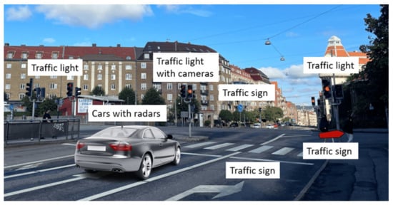
Figure 1.
An illustration of the scenario of interest.
Cameras attached to traffic lights are widely installed nowadays. Pictures and videos taken by cameras are currently mostly used for monitoring and can only be retrieved by the relevant government departments. With a radar-communication system, important traffic news, such as accident reports or temporary road obstacle locations, can be transmitted wirelessly directly to vehicles. In that case, drivers can re-plan their route in advance and avoid traffic congestion. Moreover, under extreme weather conditions, such as heavy rain and snow, the traffic signs and traffic lights are difficult to see. If the traffic information can be transmitted to vehicles wirelessly and displayed locally to the driver, fewer accidents occur. For these purposes, we require an information broadcast system. A backscatter communication system is suitable for this application. Traffic signs and lights carry certain information, which is perfect to use a tag to broadcast. In an intersection scenario, there are normally multiple signs, traffic lights, and cameras installed, so multiple tags are needed.
Radars are prevalent in modern vehicles and are used to detect the surrounding obstacles, road users, or other vehicles. FMCW radars are the most commonly used vehicle radars for their ability to detect both the position and Doppler velocity of the surrounding target [19,20]. If infrastructures are equipped with tags and vehicles have the FMCW radar installed, communication and radar sensing can be realized simultaneously. The FMCW radar chips can be reused in this radar-communication system. Only the signal processing requires an update.
In this paper, a multi-channel backscatter communication with an FMCW radar system is presented. A novel package solution for the tag is proposed. The radar-communication system is tested with commercial E-band frontend modules. The single tag measurement demonstrates the highest transmission data rate of 8 Gbps and the highest modulation order signal of 32-QAM which shows the remarkable performance of the self-packaged tag. The frequency offset between the transmitter and the receiver is estimated for range measurement. In multi-tag measurement, two tags are used in the proposed radar-communication system. 625 Mbps BPSK signals are successfully transmitted with both tags. Table 1 compares the backscatter communication performance of related works.
The paper is organized as follows. In Section 3, the principle of backscatter communication with FMCW is presented. Then, the multi-tag message separation is introduced in Section 4. In Section 5, the signal processing framework of the proposed system is introduced. The novel package solution for the tag is presented in Section 6, and its performance test results are also given in this section. The system measurement of the proposed system is presented in Section 7. Finally, the conclusion and discussion are given in Section 8.
3. Backscatter Communication with FMCW
An overview of the proposed backscatter communication system with FMCW radar structure is shown in Figure 2.

Figure 2.
The backscatter communication system with FMCW radar structure.
On the radar (vehicle) side, a local oscillator (LO) generates a low-frequency linear frequency modulated (LMF) signal. Then, the LMF signal is multiplied by a frequency multiplier to millimeter-wave frequency. An FMCW signal is generated, for which a single chirp can be represented as:
where B is the chirp bandwidth, T is the chirp duration, is the initial frequency of the chirp and is the initial phase. The FMCW signal is amplified and then sent out by an antenna. At the tag (infrastructure) side, the received FMCW signal is modulated with data and sent back to the radar. The data is modulated by mixing the FMCW with the baseband signal as
where , is the symbol period. When the signal is received by the radar, it becomes
where is the noise, is the attenuation due to path loss, is the time delay between the transmitted and the received signal at the radar side. After mixing with the local FMCW, we have
where is a fixed phase, corresponds to a fixed frequency component of . is the received symbol from the tag. Here, , , where is the range between the radar and the tag, and is the speed of light. Equation (4) can be rewritten as:
where , . By analyzing the offset frequency from the received signal , the range information can be estimated. Then after the removal of the offset frequency, the data can be recovered. The offset frequency is related to chirp bandwidth B, duration T, and the range between the radar and the tag. With wider bandwidth and shorter duration, the offset frequency is larger.
Besides the signal reflected by the tag, there is also a radar signal reflected by near objects. The radar signal reflected by other objects can be represented as
where and are the attenuation and the travel time delay of the k-th object. When mixed with the local FMCW signal, it becomes
This is a traditionally received signal of an FMCW radar. The range between radar and objects can be estimated from .
The total received signal is
Compared with the traditional backscatter communication system, the difference is the carrier signal. The FMCW signal is used instead of a single-tone CW signal. This result in a frequency offset in . When there is no tag in the view, the proposed system can work normally as an FMCW radar.
To avoid unintentional jamming between the FMCW radar signals and communication signals from tags, as well as distinguish signals from different tags, signature codes are used. This will be discussed in the next section.
4. Multi-Tag Scenario
An overview of the proposed backscatter communication system with FMCW radar structure in a multi-tag scenario is shown in Figure 3.
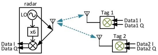
Figure 3.
The proposed backscatter communication system with FMCW radar in a multi-tag scenario.
When there are multiple tags in the view, each tag modulates individual data to the FMCW signal and sends it back to the radar side. The received signal under this scenario can be represented as
where represents the reflected signal from other objects and is the noise. When it mixes with the local FMCW, it becomes
Equation (10) shows that reflected signals from tags and objects have different offset frequency and . Assuming there are two tags and one object in the view, their spectrum can be shown in Figure 4.
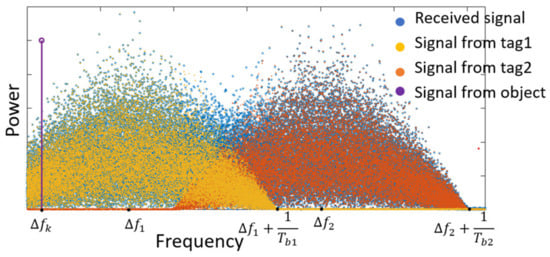
Figure 4.
The spectrum of a down-converted received signal from two tags.
The spectrum of the received signal from the object can be represented as the purple line. There is only a single frequency tone that represents , which can be selected by a bandpass filter (BPF) when its spectral power density is larger than the signal from tags. The spectrum of received signals from two tags are represented as yellow and orange dots. They have offset frequencies of and , respectively. Their symbol rates are and . When the symbol rate is large and the difference between two frequency offsets is small, the spectrum of two signals will overlap, as Figure 4 shows. The spectrum of the total signal received from the two tags can be represented by the blue dots. Two signals cannot be separated from their spectrum.
Paper [16] studied the requirement of the distance separation of tags without spectrum overlap, which is
where and are the symbol rate of two transmitted signals from two tags, is the FMCW chirp duration, B is the chirp bandwidth, c is the speed of light, and is the minimum separation range. In this case, the symbol rate of transmitted signals is limited by the distance and FMCW chirp. If the FMCW radar has a chirp bandwidth of 1 GHz, a duration of 1 ms, and the distance between the two tags is 30 m. In this case, the total symbol rate of two tags needs smaller than
By using a more advanced FMCW radar or placing two tags further apart from each other, the system will be able to transmit the signal with a higher symbol rate. A commercial FMCW radar normally has a chirp bandwidth smaller than 1 GHz, and a duration time longer than 1 ms. For the smart traffic scenario introduced in Section 2, the distance between two tags is normally a few dozen meters. In this case, it is difficult to further increase the communication symbol rate up to megabaud.
In this paper, we propose to use CDMA with backscatter communication and radar sensing system to avoid collisions between multi-tag and jamming between signals from tags and objects. For each tag, an individual signature code is used to modulate the original data at the baseband. By using the signature code to represent the symbol, the spectrum of the baseband signal is spread, and its spectral power density is decreased accordingly. On the radar side, the received signal will correlate to each signature code to recover the data of each tag.
Assume the signature code chip has a length of L bits. When the signature code correlates with itself,
The power of L bits will be summed up. When the signature code correlates with other signature codes,
When the signature code correlates with other radar reflection signals from an object, the correlation result can be represented as
where is the symbol period. If the symbol rate of the signature code is much larger than , then doesn’t change too much within time. When holds, then
This signal is removed by correlation. In this case, the correlation increases the signal-to-interference ratio (SIR) and signal-to-noise ratio (SNR) of the target tag signal. Hence, data from each tag can be distinguished.
As mentioned before, the normal radar signal from other objects appears as a single tone on the spectrum at the receiver. To maintain the normal FMCW radar sensing functionality, the single tone needs to be selected by a BPF. This requires its SIR and is high enough within the BPF’s bandwidth. From the radar signals perspective, the signals from tags are interferences. To lower the interference power, the tags in use are normally passive. Furthermore, benefitting from the signature codes, the power of the signals from tags can be re-enforced at the receiver side by applying correlation, which means that the tag does not need to provide a large, transmitted power. The idea is similar to the spread spectrum communication. In this case, the normal radar signal can guarantee its SIR to realize sensing while the data from tags can also be recovered. Alternatively, the communication signal can be reconstructed after data recovery and subtracted from the observation (10), prior to applying standard signal processing for sensing.
The main limitation of the communication data rate is the bandwidth of the radar module and the tag in use. The received signal , which is also the transmitted signal from the tag, has a bandwidth of , where is the FMCW chirp bandwidth and is the baseband signal bandwidth. need to be smaller than the RF bandwidth of the radar module and the tag. After mixing with the local FMCW signal, has a bandwidth of . It needs to be smaller than the baseband bandwidth of the radar module.
5. Signal Processing Framework
5.1. Single Tag Scenario and Range Estimation
When there is only one tag in the view, the received signal can be represented as (5) after mixing with the local FMCW signal. There is only a fixed frequency offset and a phase offset left. By using fast Fourier transformation (FFT) and a phase-locked loop (PLL), we can derive the offset frequency and offset phase. A pilot signal of long zeros can be placed ahead of the data to assist in frequency offset extraction. The distance between the radar and the tag can be calculated by
5.2. Multi-Tag Separation and Communication Processing
When there are multiple tags and objects in the view, each tag is assigned an individual signature code. The received down-converted signal can be represented as (10). The down-converted signal needs to first be correlated with each signature code to increase the SNR and SIR. The distance between tags and the radar is random, and the time delay between signals from different tags is also random. In this case, the correlation between two different signature codes is represented as
where is the time delay difference between two signals from two tags. After the correlation, there is still a little power of the signal from another tag left. Assume there are two tags. and are the signals from two tags. and are two correlation results on the radar,
where , , which means in , has the majority of the power, while in , has the majority of the power, as Figure 5 shows.
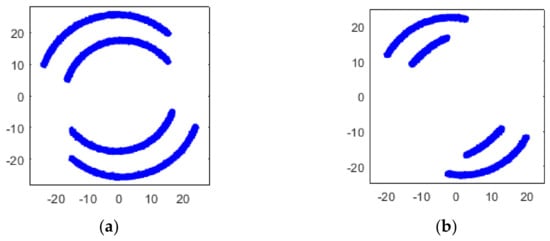
Figure 5.
Simulated constellation diagrams of (a) and (b) with of 500 Hz and of 250 Hz.
As a result, the offset frequency and phase offset can be estimated from Similarly, and can be estimated from . The offset frequency estimation has two steps. First, apply FFT to and to get a coarse frequency estimation. Second, a phase-locked loop is applied to further track the frequency and phase offset.
After removing the frequency offset from and , they become
Simulated constellation diagrams of with different are shown in Figure 6.
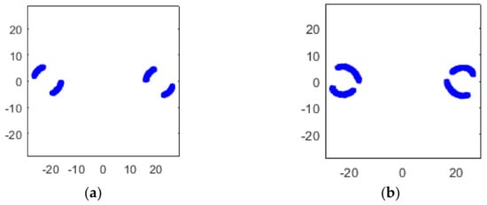
Figure 6.
Simulated constellation diagrams of with of (a) 250 Hz and (b) 500 Hz.
5.3. Equalization
To further minimize the error vector magnitude (EVM), we need to make the constellation points as concentrated as possible. This can be done via blind equalization.
To concentrate the constellation points, the interference signal from another tag needs to be removed. The part needs to be removed from , and the part needs to be removed from . Since , , and are estimated from the previous step, the interference signal in can be removed as
where is an adjustable coefficient that needs to be optimized to minimize the EVM. We do a search of from its possible value to get the smallest EVM. Equation (19) indicates , . When the first component in (21) is removed, we have the smallest EVM. In this case,
Then, (21) becomes
Follow the same procedure to remove the interference signal in and get
when
The simulated constellation diagrams after equalization with different are shown in Figure 7. Compared with Figure 6, the constellation points are more concentrated.
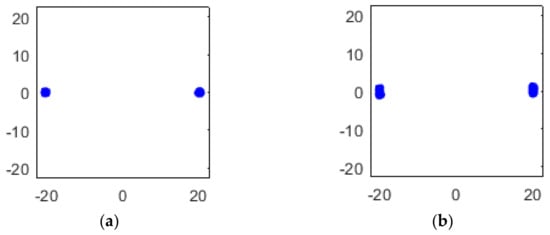
Figure 7.
Simulated constellation diagrams of with of (a) 250 Hz and (b) 500 Hz.
5.4. Spread Spectrum Signature Code Selection
As introduced in section V-B, signature codes are used to separate signals from different tags. However, it is difficult to find a group of codes that guarantee zero cross-correlation with all different time offset . In other words, (18) cannot be guaranteed to be zero with all possible values. It is preferred to have as small as possible compared to L. In this paper, the signature codes are a randomly generated set of pseudo-random sequences which have
with different lengths from 8 bits to 64 bits. If the signal power from two tags is different due to distance, one signal’s power is less than of the other one, then only one tag’s data can be recovered. Note that this ratio can be further reduced when a suitable signature code is selected. With this group of signature codes, increasing the length of the code doesn’t decrease the ratio between and L significantly. However, increasing the length of the signature code chip can increase the SNR. As a result, the EVM reduces as the length of the signature code increases. A simulation result of the EVM of recovered signal from two tags with different chip lengths and SNR is shown in Figure 8. The chip rate is 5 Gbps. With the increase of chip length, higher signal power is obtained at the receiver side. As a result, the EVM decreases.
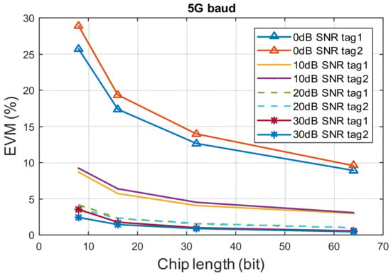
Figure 8.
EVM VS. chip length with different SNR of 5Gbps chip rate signal in two tags scenario.
5.5. Radar Sensing Performance
To study how modulated signals affect the radar sensing performance, we assume there is only one tag in the view. The radar sensing performance is related to the offset frequency estimation performance. We apply a two-step frequency estimation; First, apply FFT to get a coarse frequency estimation. Second, a phase-locked loop is applied to further track the frequency and phase offset. Here, we use a BPSK signal with a symbol rate of 5 Gbaud, and SNR of 20 dB. As Figure 9 shows, when the signature code has 8 or 16 bits, there is around a 10 Hz to 20 Hz estimation error. When the signature code has 32 bits, the estimation error is lower than 0.5 Hz, which is similar to no data modulation case. As a result, the SNR is the key factor in frequency estimation.
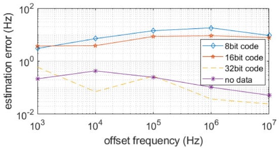
Figure 9.
Frequency estimation performance with different lengths of signature code.
6. Tag Hardware and Test Result
A package solution for the tag is presented in this section. A commercial E-band fundamental quadrature mixer MMIC (Gotmic gMR0012, Gothenburg, Sweden) [21] is packaged in a waveguide interfaced block as a tag in the proposed radar-communication system. The LO port is used as a tag input port, the RF port is used for modulated signal output, and baseband IQ ports are used to control theRF port phase-shifting regarding input LO signal. The photo of the packaged module is shown in Figure 10. On the back side of the module, two waveguide ports of WR-8 interfaces are used for signal input and output. 20 dBi waveguide interfaced antennas are connected to the tag during measurement. On the side of the module, differential quadrature IQ input port are provided by coaxial interfaces. On the front side of the module, a 200 um thick metal carrier board with etched slots are used for carrying MMIC and the U-shape slots are used for MMIC to waveguide transition. Also, a printed circuit board (PCB) is used for IQ signal connections to the MMIC.
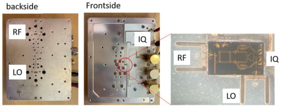
Figure 10.
A picture of the packaged chip.
Different packaging solutions have been proposed, and many of them require a PCB. PCB introduces big loss at high frequencies, which is desired to be avoided in high frequency packaging solutions [22,23,24,25]. A novel substrate-less packaging solution is proposed in the design of the tag module. The LO and RF ports are directly wire bonded to the packaging block without using any dielectric substrate to reduce cost and avoid high electric loss at these frequencies. The packaging concept is illustrated in Figure 11. A ridge waveguide is used at the interface, whose upper wall is cut open with a U-shape slot. The upper wall (green part) is 200 um thick metal carrier which also holds MMIC on it. The ridge (yellow part) is manufactured by milling on a metal block (backside of the module, invisible in this figure). The MMIC is attached above this upper wall, and the signal PAD on the MMIC is connected to the upper wall with two bonding wires across the U-slot. These bond wires act as radiation probes, and the U-slot provides a coupling between the bond wire and the ridge waveguide. The length of this slot defines the coupling frequency. From the ridge waveguide to standard rectangular waveguide, a transition as described in [26] is used. This transition’s S parameter measurement result is presented in Figure 12, where port 1 is the lumped port on the MMIC and port 2 is the wave port at the ridge waveguide. The measurement exhibits insertion-loss less than 2 dB and return-loss less than −10 dB between 70–85 GHz.
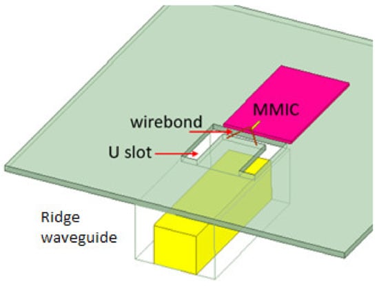
Figure 11.
An illustration of the packaging concept.
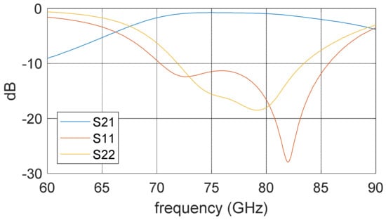
Figure 12.
The S parameter measurement result of the transition including two bonding wires and a U-slot.
The mixer used as a tag is a resistive mixer where the LO signal is split into quadrature paths, where different attenuation is applied on the path based on IQ input, and these paths are then combined into RF output. This operation principle implies an energy loss converting an LO signal to an RF signal. The packaged module is tested with −10 dBm LO input power and 1 GHz input at four different baseband ports (I+, I−, Q+, and Q−) independently. The conversion gain is plotted versus different LO frequencies in Figure 13. It can be seen that the mixer introduces a 35 dB conversion loss over the 70–90 GHz band.
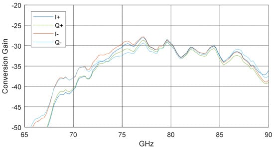
Figure 13.
The measurement result of the conversion gain with different frequencies of the self-packaged tag.
7. Measurement Result and Discussion
Two measurements are demonstrated in this paper: the single tag measurement and the dual tag measurement. The single tag measurement shows the performance of the self-packaged tag with the LMF signal as a carrier. In the dual tag measurement, two tags are used to transmit two different data streams to simulate the multi-tag scenario.
7.1. Single Tag Test
The measurement setup for the single tag test is shown in Figure 14.
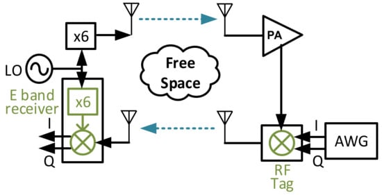
Figure 14.
The measurement setup for a single tag test.
The LMF signal is generated from a signal generator (Agilent E8257D, Santa Clara, CA, USA) with a frequency between 12.533 GHz and 13.033 GHz. The chirp rate is 0.1 Hz. An E-band six times multiplier (AT Microwave AT-AM6-7186-12, Shanghai, China) is connected after the signal generator to generate the FMCW signal with a frequency from 75.2 GHz to 78.2 GHz. The FMCW signal is sent out through an antenna over the air. At the tag side, the FMCW is first amplified by a W-band power amplifier (QuinStar QPI-W01128, Torrance, CA, USA). An arbitrary wave generator (AWG, Keysight M8195A, Santa Rosa, CA, USA) is used to generate the baseband I/Q signal. The amplified FMCW signal is mixed with the baseband I/Q signal by the self-packaged RF tag. The RF signal is sent back to the radar side. On the radar side, an E-band receiver module (Gotmic gRSC0015, Gothenburg, Sweden) [27] is used to down-convert the RF signal. The module comprises a six times multiplier and a mixer. The FMCW signal is generated inside the receiver module by the multiplier and mixed with the received RF signal. The down-converted signal is sampled by an oscilloscope (Teledyne LabMater 10 Zi-A, Thousand Oaks, CA, USA) for further post-processing. The EVM and BER are estimated by the oscilloscope. The oscilloscope and the AWG are not synchronized and running freely. The measurement distance between antennas from the radar side to the tag side is around 65 cm.
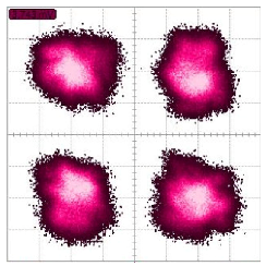
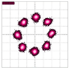
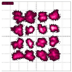
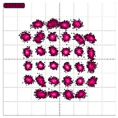
Signals with different modulation schemes have been transmitted over this backscatter communication system. The highest transmitted data rate is 8 Gbps with QPSK or 16-QAM. The highest tested modulation order signal is a 32-QAM signal with a data rate of 2.5 Gbps. Constellation diagrams of different modulation signals with their highest data rate are shown in Table 2. Their estimated EVM with different symbol rates are shown in Figure 15. Their BERs are all below 2 × 10⁻⁴. These measurement results show that the self-package tag is capable of transmitting a large bandwidth signal of 8 GHz and high modulation order signal of 32-QAM.

Table 2.
Constellation diagrams of different modulation order signals with their highest achieved data rate of single tag measurement.
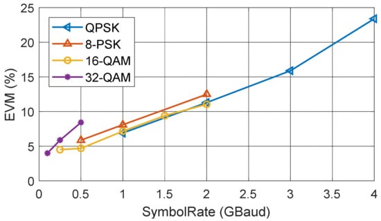
Figure 15.
EVM VS. symbol rate with different modulation order signals of single tag measurement.
7.2. Two Tags Test
The measurement setup for the two tags test is shown in Figure 16. A photo of the lab setup is shown in Figure 17. Two tags and five antennas are used in the system. A power splitter is used on the tag side to provide the FMCW signal to both tags. In this case, the power of the FMCW signal provided to tags is 3 dB smaller than the single tag test. Note that the power splitter is not a necessary component in this system. It is used only due to the shortage of amplifiers. There should be an amplifier attached to each tag.
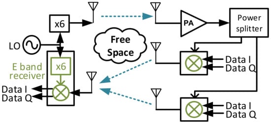
Figure 16.
A measurement setup for the two tags test.
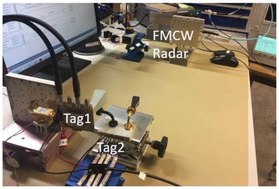
Figure 17.
A photo of the measurement setup in the lab.
The baseband signal for both tags is spectrum spread by using a different signature code. Different lengths of code and different symbol rates have been tested. In this case, only BPSK signals are transmitted. A 5 Gbps baseband signal has been transmitted with an 8-bit signature code so that the highest data rate that has been transmitted is 625 Mbps with both tags. The constellation diagrams of the received raw signal and the demodulated signals for two tags are shown in Figure 18. Before the demodulation, the received signal is a mixture of two signals from two tags. The constellation of it is cloudy. After applying the correlation with two signature codes, two signals from different tags are separated. Their constellations then become clear. By using different length signature codes, the EVM varies accordingly. The EVM of two signals are similar. Figure 19 shows the EVM decreases when chip length increases.
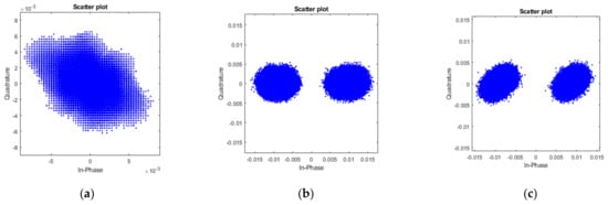
Figure 18.
Constellation diagrams of (a) received signal from two tags with 625 Mbps BPSK of each tag, (b) demodulated signal from the first tag, and (c) demodulated signal from the second tag, where 8 bits signature code are used.
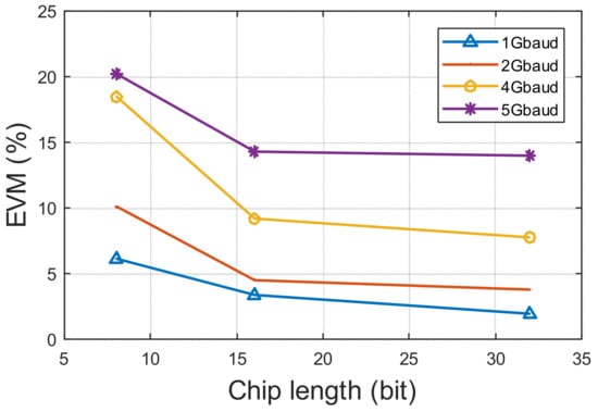
Figure 19.
EVM VS. different chip length and different symbol rate of two-tag measurement.
Due to the limited measurement distance in the lab and the slow sweep time of the signal synthesiser, the offset frequency at the receiver side is very small. To further test the system performance with larger offset frequencies, offset frequencies of 50 kHz and 49 kHz are added from the tag side by AWG. As Figure 20 shows, EVM and frequency estimation error decrease with chip length increase. Comparing Figure 19 and Figure 20, when using the same symbol rate signal in the system, higher offset frequencies cause higher EVM. For the 1 Gbuad signal used in the system, the EVM increase by around 10% when offset frequencies exist. If an FMCW with 1 GHz bandwidth and 1 ms duration time is used in this system, the frequency estimation error shown in Figure 20 will cause a 60 mm to 500 mm range estimation error with different chip lengths. This is due to an immature frequency estimation solution, and it can be further improved with more advanced processing methods.
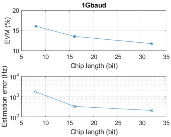
Figure 20.
EVM and frequency estimation error with different chip length of two-tag measurement.
7.3. Link Budget
The six times multiplier on the radar side gives an output power of 10 dBm. The antenna connected to it is a horn antenna (AINFO LB-12-25-A, Chengdu, China) that produces a 25 dBi gain. At the tag side, another slot array antenna provides another 22 dBi gain. The distance between the tag and the radar is around 65 cm, which introduces around 66.4 dB of free space path loss. Thus, the received LO signal at the tag side in our case is around −9.4 dBm. After using an amplifier (QuinStar QPI-W01128, Torrance, CA, USA) and a 3 dB power splitter, the LO power used for the tag is around 8 dBm without considering cable loss.
A pair of I and Q channel is used for each tag with an input power of −10 dBm at each channel. The conversion loss is around 30 dB at the frequency that we used. The RF output power from the tag is around −37 dBm. Antennas in use for two tags have 25 dBi and 20 dBi gain, respectively. On the radar side, the slot array antenna provides 22 dBi gain. The received signal power at the radar side from each tag is −56.4 dBm and −61.4 dBm, respectively.
8. Conclusions
The proposed multi-channel backscatter communication with FMCW radar is tested with commercial E-band frontend modules at 75.2 to 78.2 GHz. A novel package solution for the RF tag is proposed. The tag performance is tested for different modulation schemes and different data rates. For the single tag measurement, it demonstrates the highest data rate of 8 Gbps and the highest modulation order signal of 32-QAM compared to other related works. The frequency offset between the transmitter and the receiver can be used for range measurement. Its accuracy is related to the SNR and chip length of signature codes in use. For the multi-tag measurement, signature codes are used to separate signals from two tags. Blind equalization is applied to further decrease the EVM. By using signature codes, tags can be freely deployed.
Author Contributions
Conceptualization, S.A. and Z.S.H.; Data curation, S.A.; Funding acquisition, H.Z.; Methodology, S.A.; Project administration, H.Z.; Supervision, H.Z. and Z.S.H.; Validation, S.A. and Z.S.H.; Writing—original draft, S.A.; Writing—review & editing, X.B., H.W., H.Z. and Z.S.H. All authors have read and agreed to the published version of the manuscript.
Funding
The research was funded in part by Car2TERA project of the European Union’s Horizon 2020 research and innovation programme under grant agreement No. 824962, European Union’s Horizon 2020 project Int5Gent (957403), European Union’s Horizon 2020 project RISE6G (101017011), the National Natural Science Foundation of China under Grants 61620106001, and Chalmers Transport Area of Advance.
Institutional Review Board Statement
Not applicable.
Conflicts of Interest
The authors declare no conflict of interest.
References
- Rao, K.V.S. An overview of backscattered radio frequency identification system (RFID). In Proceedings of the 1999 Asia Pacific Microwave Conference. APMC’99. Microwaves Enter the 21st Century. Conference Proceedings (Cat. No.99TH8473), Singapore, 30 November–3 December 1999; Volume 3, pp. 746–749. [Google Scholar] [CrossRef]
- Boyer, C.; Roy, S. —Invited Paper—Backscatter Communication and RFID: Coding, Energy, and MIMO Analysis. IEEE Trans. Commun. 2014, 62, 770–785. [Google Scholar] [CrossRef]
- Griffin, J.D.; Durgin, G.D. Complete Link Budgets for Backscatter-Radio and RFID Systems. IEEE Antennas Propag. Mag. 2009, 51, 11–25. [Google Scholar] [CrossRef]
- Pala, Z.; Inanc, N. Smart Parking Applications Using RFID Technology. In Proceedings of the 2007 1st Annual RFID Eurasia, Istanbul, Turkey, 5–6 September 2007; pp. 1–3. [Google Scholar] [CrossRef]
- Nikitin, P.V.; Rao, K.V.S. Performance limitations of passive UHF RFID systems. In Proceedings of the 2006 IEEE Antennas and Propagation Society International Symposium, Albuquerque, NM, USA, 9–14 July 2006; pp. 1011–1014. [Google Scholar] [CrossRef]
- Pursula, P.; Vaha-Heikkila, T.; Muller, A.; Neculoiu, D.; Konstantinidis, G.; Oja, A.; Tuovinen, J. Millimeter-Wave Identification—A New Short-Range Radio System for Low-Power High Data-Rate Applications. IEEE Trans. Microw. Theory Technol. 2008, 56, 2221–2228. [Google Scholar] [CrossRef]
- Kimionis, J.; Bletsas, A.; Sahalos, J.N. Increased Range Bistatic Scatter Radio. IEEE Trans. Commun. 2014, 62, 1091–1104. [Google Scholar] [CrossRef]
- Muller, A.; Neculoiu, D.; Pursula, P.; Vaha-Heikkila, T.; Giacomozzi, F.; Tuovinen, J. Hybrid integrated micromachined receiver for 77 GHz millimeter wave identification systems. In Proceedings of the 2007 European Microwave Conference, Munich, Germany, 9–12 October 2007; pp. 1034–1037. [Google Scholar] [CrossRef]
- Thomas, S.J.; Wheeler, E.; Teizer, J.; Reynolds, M.S. Quadrature Amplitude Modulated Backscatter in Passive and Semipassive UHF RFID Systems. IEEE Trans. Microw. Theory Technol. 2012, 60, 1175–1182. [Google Scholar] [CrossRef]
- Thomas, S.J.; Reynolds, M.S. A 96 Mbit/sec, 15.5 pJ/bit 16-QAM modulator for UHF backscatter communication. In Proceedings of the 2012 IEEE International Conference on RFID (RFID), Orlando, FL, USA, 3–5 April 2012; pp. 185–190. [Google Scholar] [CrossRef]
- Shirane, A.; Tan, H.; Fang, Y.; Ibe, T.; Ito, H.; Ishihara, N.; Masu, K. 13.8 A 5.8 GHz RF-powered transceiver with a 113 μW 32-QAM transmitter employing the IF-based quadrature backscattering technique. In Proceedings of the 2015 IEEE International Solid-State Circuits Conference-(ISSCC) Digest of Technical Papers, San Francisco, CA, USA, 22–26 February 2015; pp. 1–3. [Google Scholar] [CrossRef]
- Schmid, C.M.; Feger, R.; Stelzer, A. Millimeter-wave phase-modulated backscatter transponder for FMCW radar applications. In Proceedings of the 2011 IEEE MTT-S International Microwave Symposium, Baltimore, MD, USA, 5–10 June 2011; pp. 1–4. [Google Scholar] [CrossRef]
- Rehammar, R.; Liang, Z.; Billade, B. Design of a Sensor Agnostic FMCW-Compatible Transponder for Automotive Applications. In Proceedings of the 2018 IEEE Conference on Antenna Measurements & Applications (CAMA), Vasteras, Sweden, 3 September 2018; pp. 1–4. [Google Scholar] [CrossRef]
- Carlowitz, C.; Vossiek, M.; Strobel, A.; Ellinger, F. Precise ranging and simultaneous high speed data transfer using mm-wave regenerative active backscatter tags. In Proceedings of the 2013 IEEE International Conference on RFID (RFID), Orlando, FL, USA, 30 April–2 May 2013; pp. 253–260. [Google Scholar] [CrossRef]
- Lazaro, A.; Lazaro, M.; Villarino, R.; Girbau, D.; de Paco, P. Car2car communication using a modulated backscatter and automotive fmcw radar. Sensors 2021, 21, 3656. [Google Scholar] [CrossRef] [PubMed]
- Cnaan-On, I.; Thomas, S.J.; Krolik, J.L.; Reynolds, M.S. Multichannel Backscatter Communication and Ranging for Distributed Sensing With an FMCW Radar. IEEE Trans. Microw. Theory Technol. 2015, 63, 2375–2383. [Google Scholar] [CrossRef]
- Sit, Y.L.; Reichardt, L.; Sturm, C.; Zwick, T. Extension of the OFDM joint radar-communication system for a multipath, multiuser scenario. In Proceedings of the 2011 IEEE RadarCon (RADAR), Kansas City, MO, USA, 23–27 May 2011; pp. 718–723. [Google Scholar] [CrossRef]
- Garmatyuk, D.; Schuerger, J.; Morton, Y.T.; Binns, K.; Durbin, M.; Kimani, J. Feasibility study of a multi-carrier dual-use imaging radar and communication system. In Proceedings of the 2007 European Radar Conference, Munich, Germany, 9–12 October 2007; pp. 194–197. [Google Scholar] [CrossRef]
- Winkler, V. Range Doppler detection for automotive FMCW radars. In Proceedings of the 2007 European Radar Conference, Munich, Germany, 10–12 October 2007; pp. 166–169. [Google Scholar] [CrossRef]
- Neemat, S.; Uysal, F.; Krasnov, O.; Yarovoy, A. Reconfigurable Range-Doppler Processing and Range Resolution Improvement for FMCW Radar. IEEE Sens. J. 2019, 19, 9294–9303. [Google Scholar] [CrossRef]
- Available online: https://gotmic.se/documents/gRSC0012B_Rev%20A01-17.pdf (accessed on 20 October 2021).
- Jameson, S.; Socher, E. A Wide-Band CMOS to Waveguide Transition at mm-Wave Frequencies With Wire-Bonds. IEEE Trans. Microw. Theory Technol. 2015, 63, 2741–2750. [Google Scholar] [CrossRef]
- Dong, Y.; Zhurbenko, V.; Hanberg, P.J.; Johansen, T.K. A “D-Band Rectangular Waveguide-to-Coplanar Waveguide Transition Using Wire Bonding Probe. J. Infrared Millim. Terahertz Waves 2018, 40, 63–79. [Google Scholar] [CrossRef]
- Ahmadi, B.; Banai, A. Substrateless Amplifier Module Realized by Ridge Gap Waveguide Technology for Millimeter-Wave Applications. IEEE Trans. Microw. Theory Technol. 2016, 64, 3623–3630. [Google Scholar] [CrossRef]
- Hassona, A.; Vassilev, V.; Zaman, A.U.; Zirath, H. Packaging Technique of Highly Integrated Circuits Based on EBG Structure for +100 GHz Applications. In Proceedings of the 2020 14th European Conference on Antennas and Propagation (EuCAP), Copenhagen, Denmark, 15–20 March 2020; pp. 1–4. [Google Scholar]
- Gatti, R.V.; Rossi, R. Wideband compact single-ridge waveguide to rectangular waveguide transitions with integrated E-plane bend. Electron. Lett. 2016, 52, 1699–1701. [Google Scholar] [CrossRef]
- Available online: https://gotmic.se/documents/gRSC0015D_Rev%20A01-17.pdf (accessed on 20 October 2021).
Publisher’s Note: MDPI stays neutral with regard to jurisdictional claims in published maps and institutional affiliations. |
© 2022 by the authors. Licensee MDPI, Basel, Switzerland. This article is an open access article distributed under the terms and conditions of the Creative Commons Attribution (CC BY) license (https://creativecommons.org/licenses/by/4.0/).
