
Quantifying and Reducing Ion Migration in Metal Halide Perovskites through Control of Mobile Ions

Abstract
1. Introduction
2. Results
3. Discussion
4. Materials and Methods
5. Conclusions
Author Contributions
Funding
Institutional Review Board Statement
Informed Consent Statement
Data Availability Statement
Acknowledgments
Conflicts of Interest
Sample Availability
References
- Zhang, W.; Eperon, G.E.; Snaith, H.J. Metal Halide Perovskites for Energy Applications. Nat. Energy 2016, 1, 16048. [Google Scholar] [CrossRef]
- Jeong, M.; Choi, I.W.; Go, E.M.; Cho, Y.; Kim, M.; Lee, B.; Jeong, S.; Jo, Y.; Choi, H.W.; Lee, J.; et al. Stable Perovskite Solar Cells with Efficiency Exceeding 24.8% and 0.3-V Voltage Loss. Science 2020, 369, 1615–1620. [Google Scholar] [CrossRef] [PubMed]
- Song, Z.; McElvany, C.L.; Phillips, A.B.; Celik, I.; Krantz, P.W.; Watthage, S.C.; Liyanage, G.K.; Apul, D.; Heben, M.J. A Technoeconomic Analysis of Perovskite Solar Module Manufacturing with Low-Cost Materials and Techniques. Energy Environ. Sci. 2017, 10, 1297–1305. [Google Scholar] [CrossRef]
- Kim, J.Y.; Lee, J.-W.; Jung, H.S.; Shin, H.; Park, N.-G. High-Efficiency Perovskite Solar Cells. Chem. Rev. 2020, 120, 7867–7918. [Google Scholar] [CrossRef]
- Seo, J.; Noh, J.H.; Seok, S. Il Rational Strategies for Efficient Perovskite Solar Cells. Acc. Chem. Res. 2016, 49, 562–572. [Google Scholar] [CrossRef]
- NREL Best Research Cell Efficiency Chart. Available online: https://www.nrel.gov/pv/cell-efficiency.html (accessed on 17 May 2023).
- Akman, E.; Ozturk, T.; Xiang, W.; Sadegh, F.; Prochowicz, D.; Tavakoli, M.M.; Yadav, P.; Yilmaz, M.; Akin, S. The Effect of B-Site Doping in All-Inorganic CsPbIxBr3−x Absorbers on the Performance and Stability of Perovskite Photovoltaics. Energy Environ. Sci. 2023, 16, 372–403. [Google Scholar] [CrossRef]
- Sadegh, F.; Akman, E.; Prochowicz, D.; Tavakoli, M.M.; Yadav, P.; Akin, S. Facile NaF Treatment Achieves 20% Efficient ETL-Free Perovskite Solar Cells. ACS Appl. Mater. Interfaces 2022, 14, 38631–38641. [Google Scholar] [CrossRef]
- Leyden, M.R.; Meng, L.; Jiang, Y.; Ono, L.K.; Qiu, L.; Juarez-Perez, E.J.; Qin, C.; Adachi, C.; Qi, Y. Methylammonium Lead Bromide Perovskite Light-Emitting Diodes by Chemical Vapor Deposition. J. Phys. Chem. Lett. 2017, 8, 3193–3198. [Google Scholar] [CrossRef]
- Zhu, Y.; Liu, Y.; Miller, K.A.; Zhu, H.; Egap, E. Lead Halide Perovskite Nanocrystals as Photocatalysts for PET-RAFT Polymerization under Visible and Near-Infrared Irradiation. ACS Macro Lett. 2020, 9, 725–730. [Google Scholar] [CrossRef]
- Dong, H.; Ran, C.; Gao, W.; Li, M.; Xia, Y.; Huang, W. Metal Halide Perovskite for Next-Generation Optoelectronics: Progresses and Prospects. eLight 2023, 3, 3. [Google Scholar] [CrossRef]
- He, C.; Liu, X. The Rise of Halide Perovskite Semiconductors. Light. Sci. Appl. 2023, 12, 15. [Google Scholar] [CrossRef]
- Motti, S.G.; Meggiolaro, D.; Barker, A.J.; Mosconi, E.; Perini, C.A.R.; Ball, J.M.; Gandini, M.; Kim, M.; De Angelis, F.; Petrozza, A. Controlling Competing Photochemical Reactions Stabilizes Perovskite Solar Cells. Nat. Photonics 2019, 13, 532–539. [Google Scholar] [CrossRef]
- Chen, B.; Rudd, P.N.; Yang, S.; Yuan, Y.; Huang, J. Imperfections and Their Passivation in Halide Perovskite Solar Cells. Chem. Soc. Rev. 2019, 48, 3842–3867. [Google Scholar] [CrossRef] [PubMed]
- Akin, S.; Bauer, M.; Uchida, R.; Arora, N.; Jacopin, G.; Liu, Y.; Hertel, D.; Meerholz, K.; Mena-Osteritz, E.; Bäuerle, P.; et al. Cyclopentadithiophene-Based Hole-Transporting Material for Highly Stable Perovskite Solar Cells with Stabilized Efficiencies Approaching 21%. ACS Appl. Energy Mater. 2020, 3, 7456–7463. [Google Scholar] [CrossRef]
- Kim, J.; Lee, S.-H.; Lee, J.H.; Hong, K.-H. The Role of Intrinsic Defects in Methylammonium Lead Iodide Perovskite. J. Phys. Chem. Lett. 2014, 5, 1312–1317. [Google Scholar] [CrossRef]
- Zhang, H.; Fu, X.; Tang, Y.; Wang, H.; Zhang, C.; Yu, W.W.; Wang, X.; Zhang, Y.; Xiao, M. Phase Segregation Due to Ion Migration in All-Inorganic Mixed-Halide Perovskite Nanocrystals. Nat. Commun. 2019, 10, 1088. [Google Scholar] [CrossRef] [PubMed]
- Wang, Y.; Gould, T.; Dobson, J.F.; Zhang, H.; Yang, H.; Yao, X.; Zhao, H. Density Functional Theory Analysis of Structural and Electronic Properties of Orthorhombic Perovskite CH3NH3PbI3. Phys. Chem. Chem. Phys. 2014, 16, 1424–1429. [Google Scholar] [CrossRef] [PubMed]
- Azpiroz, J.M.; Mosconi, E.; Bisquert, J.; De Angelis, F. Defect Migration in Methylammonium Lead Iodide and Its Role in Perovskite Solar Cell Operation. Energy Environ. Sci. 2015, 8, 2118–2127. [Google Scholar] [CrossRef]
- Bi, E.; Song, Z.; Li, C.; Wu, Z.; Yan, Y. Mitigating Ion Migration in Perovskite Solar Cells. Trends Chem. 2021, 3, 575–588. [Google Scholar] [CrossRef]
- Mei, H.; Wang, Z.-Y.; Zhai, Y.; Zhu, Q.-Q.; Wang, L.; Liang, P. Understanding the Effect of Intrinsic Defects in Lead-Free Vacancy-Ordered Double Perovskites Cs2PdBr6. J. Phys. Chem. C 2022, 126, 17875–17884. [Google Scholar] [CrossRef]
- Bertoluzzi, L.; Boyd, C.C.; Rolston, N.; Xu, J.; Prasanna, R.; O’Regan, B.C.; McGehee, M.D. Mobile Ion Concentration Measurement and Open-Access Band Diagram Simulation Platform for Halide Perovskite Solar Cells. Joule 2020, 4, 109–127. [Google Scholar] [CrossRef]
- Liu, J.; Hu, M.; Dai, Z.; Que, W.; Padture, N.P.; Zhou, Y. Correlations between Electrochemical Ion Migration and Anomalous Device Behaviors in Perovskite Solar Cells. ACS Energy Lett. 2021, 6, 1003–1014. [Google Scholar] [CrossRef]
- Wang, S.; Jiang, Y.; Juarez-Perez, E.J.; Ono, L.K.; Qi, Y. Accelerated Degradation of Methylammonium Lead Iodide Perovskites Induced by Exposure to Iodine Vapour. Nat. Energy 2016, 2, 16195. [Google Scholar] [CrossRef]
- Zhu, Q.; Cox, D.E.; Fischer, J.E.; Kniaz, K.; McGhie, A.R.; Zhou, O. Intercalation of Solid C60 with Iodine. Nature 1992, 355, 712–714. [Google Scholar] [CrossRef]
- Li, X.; Fu, S.; Liu, S.; Wu, Y.; Zhang, W.; Song, W.; Fang, J. Suppressing the Ions-Induced Degradation for Operationally Stable Perovskite Solar Cells. Nano Energy 2019, 64, 103962. [Google Scholar] [CrossRef]
- Kim, S.; Bae, S.; Lee, S.-W.; Cho, K.; Lee, K.D.; Kim, H.; Park, S.; Kwon, G.; Ahn, S.-W.; Lee, H.-M.; et al. Relationship between Ion Migration and Interfacial Degradation of CH3NH3PbI3 Perovskite Solar Cells under Thermal Conditions. Sci. Rep. 2017, 7, 1200. [Google Scholar] [CrossRef]
- Wang, Y.; Wu, T.; Barbaud, J.; Kong, W.; Cui, D.; Chen, H.; Yang, X.; Han, L. Stabilizing Heterostructures of Soft Perovskite Semiconductors. Science 2019, 365, 687–691. [Google Scholar] [CrossRef]
- Yang, T.-Y.; Jeon, N.J.; Shin, H.-W.; Shin, S.S.; Kim, Y.Y.; Seo, J. Achieving Long-Term Operational Stability of Perovskite Solar Cells with a Stabilized Efficiency Exceeding 20% after 1000 h. Adv. Sci. 2019, 6, 1900528. [Google Scholar] [CrossRef]
- Li, D.; Dong, X.; Cheng, P.; Song, L.; Wu, Z.; Chen, Y.; Huang, W. Metal Halide Perovskite/Electrode Contacts in Charge-Transporting-Layer-Free Devices. Adv. Sci. 2022, 9, 2203683. [Google Scholar] [CrossRef] [PubMed]
- Kato, Y.; Ono, L.K.; Lee, M.V.; Wang, S.; Raga, S.R.; Qi, Y. Silver Iodide Formation in Methyl Ammonium Lead Iodide Perovskite Solar Cells with Silver Top Electrodes. Adv. Mater. Interfaces 2015, 2, 1500195. [Google Scholar] [CrossRef]
- Zhang, D.; Li, D.; Hu, Y.; Mei, A.; Han, H. Degradation Pathways in Perovskite Solar Cells and How to Meet International Standards. Commun. Mater. 2022, 3, 58. [Google Scholar] [CrossRef]
- Haeger, T.; Heiderhoff, R.; Riedl, T. Thermal Properties of Metal-Halide Perovskites. J. Mater. Chem. C Mater. 2020, 8, 14289–14311. [Google Scholar] [CrossRef]
- Bai, Q.; Yang, H.; Nan, C.; Wang, H.; Chen, Z. Analysis of the Electrochemical Reactions and Ions Migration for Crystalline Silicon Solar Module under High System Voltage. Sol. Energy 2021, 225, 718–725. [Google Scholar] [CrossRef]
- Wilson, M.; Savtchouk, A.; Edelman, P.; Marinskiy, D.; Lagowski, J. Drift Characteristics of Mobile Ions in SiNx Films and Solar Cells. Sol. Energy Mater. Sol. Cells 2015, 142, 102–106. [Google Scholar] [CrossRef]
- Xu, J.; Boyd, C.C.; Yu, Z.J.; Palmstrom, A.F.; Witter, D.J.; Larson, B.W.; France, R.M.; Werner, J.; Harvey, S.P.; Wolf, E.J.; et al. Triple-Halide Wide–Band Gap Perovskites with Suppressed Phase Segregation for Efficient Tandems. Science 2020, 367, 1097–1104. [Google Scholar] [CrossRef]
- Saidaminov, M.I.; Kim, J.; Jain, A.; Quintero-Bermudez, R.; Tan, H.; Long, G.; Tan, F.; Johnston, A.; Zhao, Y.; Voznyy, O.; et al. Suppression of Atomic Vacancies via Incorporation of Isovalent Small Ions to Increase the Stability of Halide Perovskite Solar Cells in Ambient Air. Nat. Energy 2018, 3, 648–654. [Google Scholar] [CrossRef]
- Maurel, A.; Armand, M.; Grugeon, S.; Fleutot, B.; Davoisne, C.; Tortajada, H.; Courty, M.; Panier, S.; Dupont, L. Poly(Ethylene Oxide)−LiTFSI Solid Polymer Electrolyte Filaments for Fused Deposition Modeling Three-Dimensional Printing. J. Electrochem. Soc. 2020, 167, 070536. [Google Scholar] [CrossRef]
- Porcarelli, L.; Gerbaldi, C.; Bella, F.; Nair, J.R. Super Soft All-Ethylene Oxide Polymer Electrolyte for Safe All-Solid Lithium Batteries. Sci. Rep. 2016, 6, 19892. [Google Scholar] [CrossRef]
- Mahapatra, A.; Runjhun, R.; Nawrocki, J.; Lewiński, J.; Kalam, A.; Kumar, P.; Trivedi, S.; Tavakoli, M.M.; Prochowicz, D.; Yadav, P. Elucidation of the Role of Guanidinium Incorporation in Single-Crystalline MAPbI3 Perovskite on Ion Migration and Activation Energy. Phys. Chem. Chem. Phys. 2020, 22, 11467–11473. [Google Scholar] [CrossRef]
- Abdi-Jalebi, M.; Andaji-Garmaroudi, Z.; Pearson, A.J.; Divitini, G.; Cacovich, S.; Philippe, B.; Rensmo, H.; Ducati, C.; Friend, R.H.; Stranks, S.D. Potassium- and Rubidium-Passivated Alloyed Perovskite Films: Optoelectronic Properties and Moisture Stability. ACS Energy Lett. 2018, 3, 2671–2678. [Google Scholar] [CrossRef] [PubMed]
- Abdi-Jalebi, M.; Andaji-Garmaroudi, Z.; Cacovich, S.; Stavrakas, C.; Philippe, B.; Richter, J.M.; Alsari, M.; Booker, E.P.; Hutter, E.M.; Pearson, A.J.; et al. Maximizing and Stabilizing Luminescence from Halide Perovskites with Potassium Passivation. Nature 2018, 555, 497–501. [Google Scholar] [CrossRef] [PubMed]
- Kim, M.K.; Lee, H.S.; Pae, S.R.; Kim, D.-J.; Lee, J.-Y.; Gereige, I.; Park, S.; Shin, B. Effects of Temperature and Coating Speed on the Morphology of Solution-Sheared Halide Perovskite Thin-Films. J. Mater. Chem. A Mater. 2018, 6, 24911–24919. [Google Scholar] [CrossRef]
- Tabi, G.D.; Pham, H.T.; Zhan, H.; Walter, D.; Mayon, A.O.; Peng, J.; Duong, T.; Shehata, M.M.; Shen, H.; Duan, L.; et al. LiI Doping of Mixed-Cation Mixed-Halide Perovskite Solar Cells: Defect Passivation, Controlled Crystallization and Transient Ionic Response. Mater. Today Phys. 2022, 27, 100822. [Google Scholar] [CrossRef]
- Bu, T.; Liu, X.; Zhou, Y.; Yi, J.; Huang, X.; Luo, L.; Xiao, J.; Ku, Z.; Peng, Y.; Huang, F.; et al. A Novel Quadruple-Cation Absorber for Universal Hysteresis Elimination for High Efficiency and Stable Perovskite Solar Cells. Energy Environ. Sci. 2017, 10, 2509–2515. [Google Scholar] [CrossRef]
- Zhang, C.; Wang, Y.; Lin, X.; Wu, T.; Han, Q.; Zhang, Y.; Han, L. Effects of A Site Doping on the Crystallization of Perovskite Films. J. Mater. Chem. A Mater. 2021, 9, 1372–1394. [Google Scholar] [CrossRef]
- Hu, Y.; Si, S.; Mei, A.; Rong, Y.; Liu, H.; Li, X.; Han, H. Stable Large-Area (10 × 10 Cm2) Printable Mesoscopic Perovskite Module Exceeding 10% Efficiency. Sol. RRL 2017, 1, 1600019. [Google Scholar] [CrossRef]
- Neukom, M.; Züfle, S.; Jenatsch, S.; Ruhstaller, B. Opto-Electronic Characterization of Third-Generation Solar Cells. Sci. Technol. Adv. Mater. 2018, 19, 291–316. [Google Scholar] [CrossRef]
- Bertoluzzi, L.; Belisle, R.A.; Bush, K.A.; Cheacharoen, R.; McGehee, M.D.; O’Regan, B.C. In Situ Measurement of Electric-Field Screening in Hysteresis-Free PTAA/FA0.83Cs0.17Pb(I0.83Br0.17)3/C60 Perovskite Solar Cells Gives an Ion Mobility of ∼3 × 10⁻⁷ Cm2/(V s), 2 Orders of Magnitude Faster than Reported for Metal-Oxide-Contacted Perovskite Cells with Hysteresis. J. Am. Chem. Soc. 2018, 140, 12775–12784. [Google Scholar] [CrossRef]
- Riquelme, A.J.; Valadez-Villalobos, K.; Boix, P.P.; Oskam, G.; Mora-Seró, I.; Anta, J.A. Understanding Equivalent Circuits in Perovskite Solar Cells. Insights from Drift-Diffusion Simulation. Phys. Chem. Chem. Phys. 2022, 24, 15657–15671. [Google Scholar] [CrossRef]
- Yoo, S.-M.; Yoon, S.J.; Anta, J.A.; Lee, H.J.; Boix, P.P.; Mora-Seró, I. An Equivalent Circuit for Perovskite Solar Cell Bridging Sensitized to Thin Film Architectures. Joule 2019, 3, 2535–2549. [Google Scholar] [CrossRef]
- von Hauff, E. Impedance Spectroscopy for Emerging Photovoltaics. Journal. Phys. Chem. C 2019, 123, 11329–11346. [Google Scholar] [CrossRef]
- Suvarna, R.P.; Rao, K.R.; Subbarangaiah, K. A Simple Technique for a.c. Conductivity Measurements. Bull. Mater. Sci. 2002, 25, 647–651. [Google Scholar] [CrossRef]
- Bischak, C.G.; Hetherington, C.L.; Wu, H.; Aloni, S.; Ogletree, D.F.; Limmer, D.T.; Ginsberg, N.S. Origin of Reversible Photoinduced Phase Separation in Hybrid Perovskites. Nano Lett. 2017, 17, 1028–1033. [Google Scholar] [CrossRef] [PubMed]
- Draguta, S.; Sharia, O.; Yoon, S.J.; Brennan, M.C.; Morozov, Y.V.; Manser, J.S.; Kamat, P.V.; Schneider, W.F.; Kuno, M. Rationalizing the Light-Induced Phase Separation of Mixed Halide Organic–Inorganic Perovskites. Nat. Commun. 2017, 8, 200. [Google Scholar] [CrossRef] [PubMed]


| Vacancy | |
|---|---|
| 0.58 eV | |
| 0.84 eV | |
| 2.31 eV |
| Device | No (cm−3) | µ (cm2/Vs) | Electronic Mobility (cm2/Vs) |
|---|---|---|---|
| Solid State Electrolytes (Lithium Lanthanum Zirconium Oxide) | ~5 × 10¹⁸ to 5 × 10²⁰ | ~10−10 to 10−14 | 0.06 |
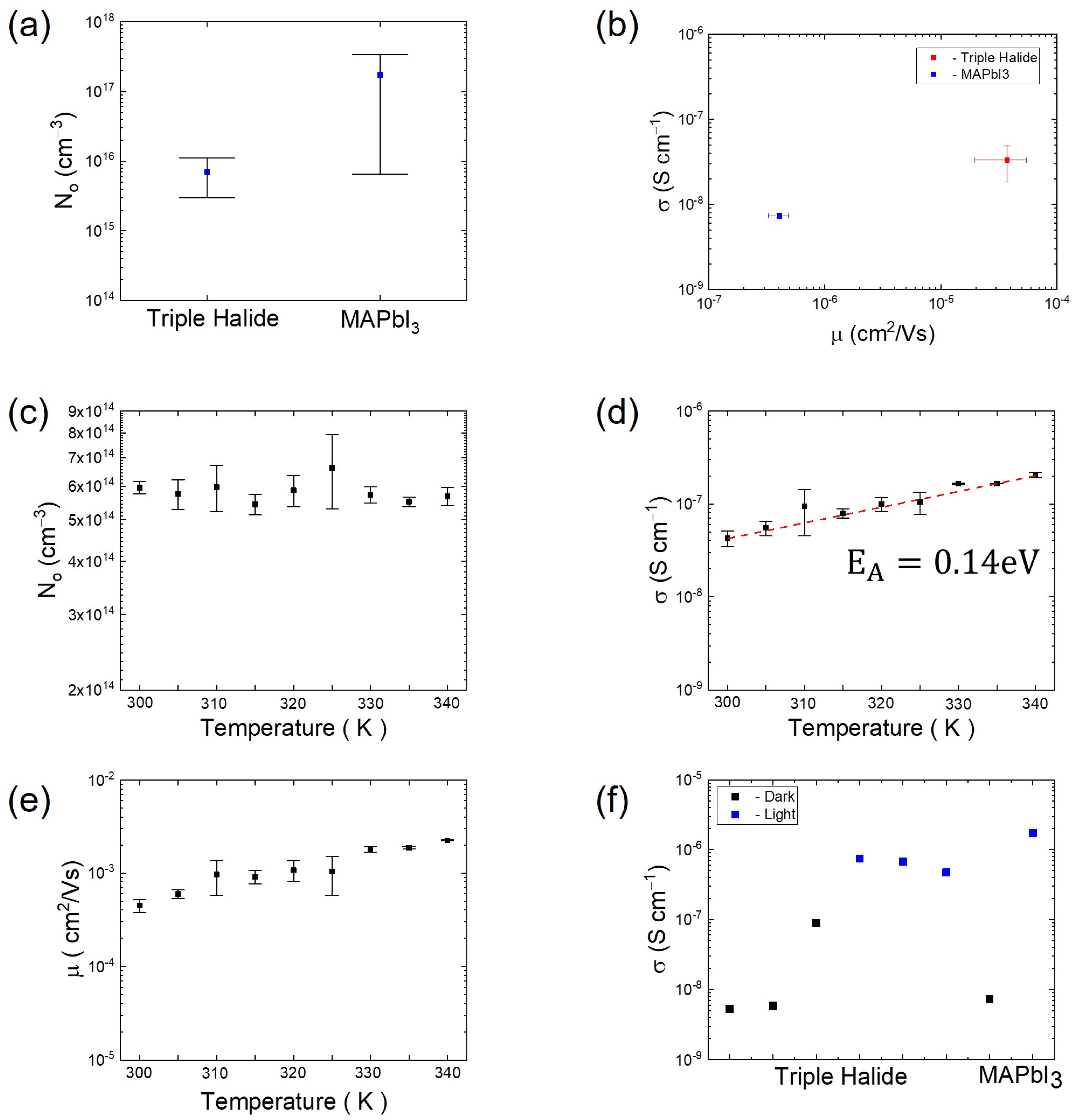
| MAPbI3 | 2 × 10¹⁷ | 8 × 10⁻⁶ | 20 to 71 |
| Triple Halide | 5 × 10¹⁵ | 3 × 10⁻⁴ | 11 to 40 |
| Silicon | 0 | 0 | ~160 |
Disclaimer/Publisher’s Note: The statements, opinions and data contained in all publications are solely those of the individual author(s) and contributor(s) and not of MDPI and/or the editor(s). MDPI and/or the editor(s) disclaim responsibility for any injury to people or property resulting from any ideas, methods, instructions or products referred to in the content. |
© 2023 by the authors. Licensee MDPI, Basel, Switzerland. This article is an open access article distributed under the terms and conditions of the Creative Commons Attribution (CC BY) license (https://creativecommons.org/licenses/by/4.0/).
Share and Cite
Penukula, S.; Estrada Torrejon, R.; Rolston, N. Quantifying and Reducing Ion Migration in Metal Halide Perovskites through Control of Mobile Ions. Molecules 2023, 28, 5026. https://doi.org/10.3390/molecules28135026
Penukula S, Estrada Torrejon R, Rolston N. Quantifying and Reducing Ion Migration in Metal Halide Perovskites through Control of Mobile Ions. Molecules. 2023; 28(13):5026. https://doi.org/10.3390/molecules28135026
Chicago/Turabian StylePenukula, Saivineeth, Rodrigo Estrada Torrejon, and Nicholas Rolston. 2023. "Quantifying and Reducing Ion Migration in Metal Halide Perovskites through Control of Mobile Ions" Molecules 28, no. 13: 5026. https://doi.org/10.3390/molecules28135026
APA StylePenukula, S., Estrada Torrejon, R., & Rolston, N. (2023). Quantifying and Reducing Ion Migration in Metal Halide Perovskites through Control of Mobile Ions. Molecules, 28(13), 5026. https://doi.org/10.3390/molecules28135026