Abstract
Wind energy has become a cornerstone of sustainable electricity generation, yet the reliable integration of wind energy conversion systems (WECSs) into modern grids remains challenged by dynamic variations in wind speed and stringent fault ride-through (FRT) requirements. Among the available technologies, the Doubly Fed Induction Generator (DFIG) and the Permanent Magnet Synchronous Generator (PMSG) dominate commercial applications; however, a comprehensive comparative assessment under diverse grid and fault scenarios is still limited. This study addresses this gap by systematically evaluating the performance of DFIG- and PMSG-based WECSs across three operating stages: (i) normal operation at constant speed, (ii) variable wind speed operation, and (iii) grid fault conditions including single-line-to-ground, line-to-line, and three-phase faults. To enhance fault resilience, a DC-link Braking Chopper is integrated into both systems, ensuring a fair evaluation of transient stability and compliance with low-voltage ride-through (LVRT) requirements. The analysis, performed using MATLAB/Simulink, focuses on active and reactive power, rotor speed, pitch angle, and DC-link voltage dynamics. The results reveal that PMSG exhibits smoother transient responses and lower overshoot compared to DFIG. Under fault conditions, the DC-link Braking Chopper effectively suppresses voltage spikes in both systems, with DFIG achieving faster reactive power recovery in line with grid code requirements, while PMSG ensures more stable rotor dynamics with lower oscillations. The findings highlight the complementary strengths of both technologies and provide useful insights for selecting appropriate WECS configurations to improve grid integration and fault ride-through capability.
1. Introduction
The urgent need to mitigate climate change and reduce dependence on fossil fuels has accelerated the global transition towards renewable energy. Among the available alternatives, wind energy has emerged as a dominant and mature source of clean electricity, with installed global capacity surpassing 1000 GW in 2024 [1]. As wind farms expand in scale and complexity, the choice of generator technology has become a central design consideration that significantly influences system performance, cost, reliability, and grid integration capabilities. Two primary generator technologies dominate contemporary WECSs: the DFIG and the PMSG. The DFIG configuration, characterized by a partially rated converter, has long been favored in medium- and large-scale wind turbines due to its cost-effectiveness and flexible power control capabilities [2,3]. Nevertheless, the reliance on slip rings and rotor-side converters introduces maintenance challenges and limits its fault ride-through (FRT) performance under severe grid disturbances [4]. To address these limitations, numerous studies have proposed advanced LVRT strategies—such as crowbar protection, DC choppers, series dynamic braking resistors, modified super-twisting sliding mode control, fuzzy gray wolf optimization, and coordinated reactive current injection—to enhance DFIG survivability during deep voltage sags [5]. By contrast, PMSG-based wind turbines use full-scale converters, enabling complete decoupling between the turbine and the grid. This enhances system controllability and robustness under grid disturbances [6]. PMSGs also benefit from higher efficiency, elimination of excitation losses, and lower maintenance due to the absence of slip rings and brushes [7,8]. These features make them highly suitable for offshore applications and isolated microgrids, where reliability and minimal maintenance are critical [9]. Recent studies demonstrate that PMSG systems achieve robust low-voltage support using advanced grid-forming and grid-following control strategies, supported by DC-link energy buffers. In [10], series dynamic braking resistors (SDBRs) are implemented in both DFIG- and PMSG-based systems to enhance their dynamic response during severe disturbances. The inclusion of SDBRs mitigates rotor overcurrent, reduces torque oscillations, and improves the systems’ ability to LVRT events without triggering protection mechanisms. This approach ensures a fairer comparison by equipping both generator types with a common external damping mechanism, highlighting their intrinsic differences under identical enhanced conditions. Several comparative studies have examined DFIG- and PMSG-based WECSs from different perspectives. For instance, ref. [11] conducted a detailed transient stability analysis under symmetrical and asymmetrical grid faults, highlighting PMSG’s faster voltage recovery and reduced torque oscillations. Similarly, ref. [12,13] analyzed control strategies under variable wind speeds, concluding that PMSGs achieve superior efficiency and dynamic response through vector control and MPPT algorithms. From an economic perspective, M. Mahmoud and H. Elshaer [14] demonstrated that while PMSG systems incur higher initial investment costs, they achieve lower Levelized Cost of Energy (LCOE) over a 20-year lifecycle due to reduced losses and maintenance requirements. Moreover, ref. [15,16,17] evaluated hybrid approaches that integrate the cost advantages of DFIG with the robustness of PMSG for multi-terminal HVDC-connected wind farms. Mohamed Abdeen and Saleh Al Dawsari [18] investigated the ability of a combined inertial controller and proportional resonant (PR) controller to support the system frequency in a DFIG, and the optimum values of the PR controller parameters to minimize frequency deviation and overshoot were determined. In recent years, cutting-edge Artificial Intelligence (AI) techniques have been increasingly applied to wind turbine control. For example, deep reinforcement learning (DRL) frameworks have been proposed for optimizing wind turbine power output while mitigating noise emissions and dynamically adapting to turbulent wind conditions, demonstrating flexibility and superior performance compared to conventional control methods [19]. Integrating such AI-based control strategies into both DFIG and PMSG systems could significantly elevate their operational efficiency and grid-support capabilities under challenging conditions. Recent research also emphasizes the need for compliance with stringent grid codes, where both generator types must support voltage and frequency regulation in high-renewable penetration scenarios [20]. Despite these advances, a significant gap remains in the literature. Many previous studies either rely on manufacturer-specific data or evaluate DFIG and PMSG under differing assumptions, wind profiles, or control topologies, making direct performance comparison challenging [21,22,23]. Despite numerous comparative studies on DFIG and PMSG technologies, a unified and fair assessment that simultaneously examines their dynamic performance, fault tolerance, and grid code compliance under identical operating conditions is lacking. This study addresses this gap by developing detailed MATLAB/Simulink models for both systems with identical turbine ratings, control structures, and fault parameters. The key novelty lies in the integration of a DC-link braking chopper into configurations, enabling an equitable evaluation of their FRT capabilities and providing new insights into transient response, reactive power recovery, and overall stability under various grid disturbance scenarios. This paper is organized as follows: Section 1 introduces the background and objectives of the study. Section 2 describes the system configurations and the proposed techniques for the four operating scenarios. Section 3 presents the MATLAB/Simulink simulation models, including the obtained results and their comparative analysis. Finally, Section 4 summarizes the main findings and outlines the conclusions of the study and the future scope of this work.
2. Wind Energy Conversion System (WECS)
Powering an electrical generator using mechanical energy converted from wind is the goal of a WECS [24]. As demonstrated in Figure 1, the WECS primarily embraces three categories of components: aerodynamic, mechanical, and electrical.

Figure 1.
The standard setup of a traditional WECS.
Figure 1 depicts the main components of a WECS connected to the grid: gearbox, generator, and power converters. The turbine generates wind power, which is calculated using the following:
This equation uses the power coefficient (), air density (), turbine blade area (), and wind speed (). At sea level, air density is 1.225 kg/m3 at 288 K. The power coefficient represents the turbine’s efficiency in converting wind kinetic energy to mechanical energy, depending on the tip speed ratio (TSR, λ) and blade pitch angle (β). The TSR is defined as the ratio of the blade tip speed to wind speed [25]:
Replacing (2) in (1), we have the following:
where R is the rotor radius (m). The wind turbine’s output torque is given as follows:
2.1. Comparison of Different WECS Types
Wind turbines are generally classified into two categories based on their speed regulation: fixed-speed and variable-speed systems. Variable-speed WECSs can be further divided into those utilizing partial-scale power converters and those with full-scale power converters [26]. For large-scale applications, three main WECS configurations are commonly employed. The first is a fixed-speed, grid-connected system that operates close to the synchronous speed, typically using squirrel cage induction generators (SCIGs). The second configuration involves a variable-speed system such as the DFIG, which uses a partial-scale back-to-back converter to control rotor currents, while the stator remains directly connected to the grid [7]. The third is a fully variable-speed system equipped with a full-scale power converter and a synchronous generator, which may be a PMSG or an electrically excited synchronous generator (EESG), allowing full decoupling from grid frequency and improved control capabilities [27].
2.2. Generator Structures of WECSs
The generator structure represents the core of WECSs, as it directly influences efficiency, reliability, and the overall cost of energy production. Among the available topologies, the DFIG and the PMSG have emerged as the two dominant structures in modern wind turbines [28]. The structural differences between DFIG and PMSG systems lie mainly in their converter requirements, excitation methods, and mechanical design, which in turn determine their operational performance under variable wind and grid conditions.
2.3. System Overview and Components of DFIG-Based WECSs
The DFIG-based WECS comprises several key elements, including the wind turbine with a drivetrain, pitch control unit, DC-link capacitor, protection system, coupling transformer, and the generator itself, as shown in Figure 2 [29]. In this configuration, the DFIG connects directly to the grid through the stator, while the rotor is interfaced via a partially rated back-to-back AC/DC/AC converter. This converter processes only a fraction (approximately 25–30%) of the total power, yet enables full dynamic control of the generator. A four-quadrant voltage source converter VSC incorporating IGBT switches manages power flow in both directions, facilitating variable-speed operation [30]. The rotor-side converter (RSC) and grid-side converter (GSC) are linked through a DC-link capacitor, ensuring stable voltage levels and energy exchange. The RSC controls rotor currents to regulate electromagnetic torque and excitation, allowing for both sub-synchronous and super-synchronous modes of operation.
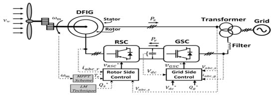
Figure 2.
Components of DFIG-based WECSs.
Control Strategy for DFIG
Figure 3 illustrates the detailed DFIG wind turbine model, where the stator is directly connected to the grid and the rotor is interfaced through a back-to-back VSC linked via a DC-link capacitor. In this work, a DC-link braking chopper is integrated into the DFIG model to enhance transient performance and FRT capability during severe grid voltage sags. The chopper effectively dissipates excess transient energy, prevents DC-link overvoltage, and mitigates oscillations, thereby improving the stability and reliability of the DFIG under grid disturbances. This approach represents a practical protection enhancement that can serve as an alternative to the conventional crowbar circuit while ensuring compliance with modern grid code requirements.
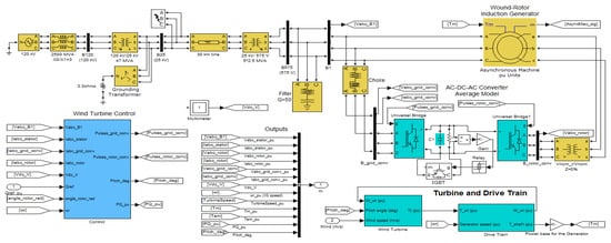
Figure 3.
Detailed DFIG wind turbine model.
Figure 4 shows the general control structure of a DFIG-based WECS. The RSC controls the electromagnetic torque and regulates reactive power exchange, while the GSC maintains DC-link voltage stability, maintains synchronization with the grid through a phase-locked loop (PLL) mechanism, and contributes to grid reactive power support. Vector control based on Park’s transformation is applied, where the d-axis and q-axis components of the rotor current independently control active and reactive power, ensuring robust operation in both sub-synchronous and super-synchronous modes [31,32]. The dynamic behavior of the machine can be described using voltage equations expressed in the d-q reference frame, as follows [33]:
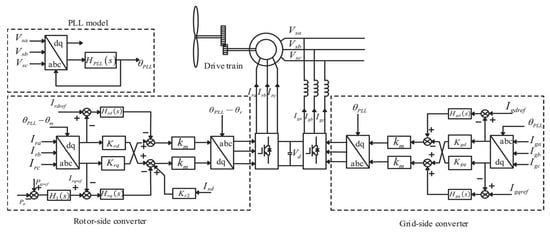
Figure 4.
General control structure of a DFIG-based WECS.
- Vsd and Vsq represent the stator d-axis and q-axis voltages.
- Isd and Isq denote the stator d-axis and q-axis currents, Vrd and Vrq represent the rotor d-axis and q-axis voltages, Ird and Irq denote the rotor d-axis and q-axis currents, Rd and Rq indicate the rotor d-axis and q-axis fluxes, Rs and Rr signify the stator and rotor resistances, respectively, and ꞷslip refers to the slip speed [34].
The corresponding flow linkages are expressed as follows:
In this context, Ls and Lr signify the self-inductances of the stator and rotor, respectively, whereas Lm denotes the mutual Inductance. The stator active power Ps and reactive power Qs are represented as follows:
In the d–q reference frame, the GSC is modeled as follows:
where igd and igq denote the grid d-axis and q-axis currents, vgd and vgq represent the grid d-axis and q-axis voltages, and Rg and Lg denote the resistance and inductance of the GSC, respectively. The electromagnetic torque is obtained by the following:
T = −(3/2) P (Lm/Ls) Φsd Iqr
In this model, P denotes the number of pole pairs, while Lm and Ls_ represent the magnetizing and stator inductances, respectively. The d-axis stator flux is indicated by Φsd and Iqr corresponds to the rotor current along the q-axis. This current directly influences the electromagnetic torque T, thereby affecting the active power flow. The reference value of Iqr is derived based on the expressions provided in Equations (2)–(6). A PI controller processes the rotor speed error to generate the corresponding torque reference Tref.
2.4. PMSG-Based WECSs
Most synchronous generator-based wind energy systems adopt a direct-drive configuration. In these systems, the stator contains three-phase windings, while the rotor is powered either by external excitation, as in Wound Rotor Synchronous Generators (WRSGs), or by built-in permanent magnets, as in PMSGs. The turbine rotor drives the generator shaft directly, eliminating the need for a mechanical gearbox [35]. PMSGs are brushless, self-excited machines and are generally categorized based on the placement of their permanent magnets. The first type employs surface-mounted magnets affixed to the rotor exterior, making it suitable for low-speed turbines due to enhanced mechanical stability at higher speeds. The second type integrates interior-mounted magnets within the rotor structure, which improves mechanical integrity under high-speed operation.
Figure 5 illustrates the configuration of a direct-drive (WTG) based on a PMSG connected to the grid. This variable-speed WTG operates without a gearbox and utilizes a full-scale power electronics interface on both the stator and grid sides. The system includes two IGBT-based converters: an AC–DC (SSC) and a DC–AC (GSC), interconnected via a DC link. The converter’s power rating matches the full output capacity of the generator [36].
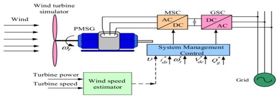
Figure 5.
PMSG-based wind turbine.
The GSC regulates the turbine speed and ensures synchronization with grid conditions. To maintain power quality and system stability, PMSG-based systems offer several advantages, such as compact size, high power density, long lifespan, low rotational inertia, mechanical simplicity, and high efficiency. Their self-excitation capability and direct-drive operation eliminate the need for a gearbox, which further reduces mechanical losses and maintenance requirements. Compared to DFIGs, PMSGs exhibit better grid integration performance and improved dynamic response. However, the inclusion of a full-scale power converter results in higher system cost and increased power losses [37].
Control Strategy for PMSG
The control strategy of the PMSG-based WECS is divided into two main parts: MSC control and GSC control, as illustrated in Figure 6. The MSC is primarily responsible for regulating the electromagnetic torque and extracting the maximum power by implementing Maximum Power Point Tracking (MPPT) techniques. On the other hand, the GSC ensures the regulation of the DC-link voltage and maintains synchronization with the grid through a PLL mechanism. Both controllers employ vector control (field-oriented control) in the synchronous d–q reference frame, enabling decoupled control of active and reactive power [15,38].
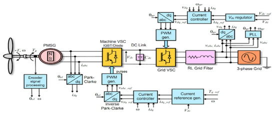
Figure 6.
Structural diagram of WECS utilizing PMSG.
Instead of an excitation coil, the PMSG employs permanent magnets [39], enabling a reduced pole pitch and making it well-suited for low-speed wind turbine applications. The stator voltages in the d–q reference frame denoted by vdm and vqm can be expressed as follows:
The stator winding resistance per phase is Ra, the stator currents on the d- and q-axes are idm and iqm, respectively, the speed of the dq reference frame is , the stator inductances on the d- and q-axes are Ld and Lq, respectively; is the rotor flux linkage, and p = d/dt is the derivative operator.
The inductances Ld and Lq can be expressed as follows:
Ldm and Lqm are the magnetizing inductances in the d- and q-axes, while and are the stator and rotor leakage inductances. The electromagnetic torque Te is calculated as follows, where P is the number of pole pairs:
Figure 7 illustrates the detailed PMSG wind turbine model, which utilizes a full-scale back-to-back converter, which decouples the generator from the grid and provides greater flexibility in control. In this work, a DC-link braking chopper is integrated into the PMSG model to ensure stable operation and FRT capability under severe grid voltage disturbances. The braking chopper dissipates surplus energy accumulated in the DC-link, thereby preventing overvoltage, reducing oscillations, and maintaining system reliability. This protection scheme represents the standard approach for full-scale converter-based generators and aligns with practical implementations required by modern grid codes. To ensure a fair comparison between both wind generator technologies, the same protection strategy was also applied to the DFIG model.
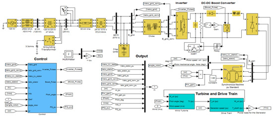
Figure 7.
Detailed PMSG wind turbine model.
3. Pitch Angle Controller
The pitch angle controller plays a crucial role in regulating the aerodynamic power extracted by the wind turbine. Its primary objective is to maintain the output power close to the rated value and to prevent mechanical and electrical overstress under high wind speed conditions. The control principle is essentially similar for both DFIG- and PMSG-based systems, where a Proportional–Integral (PI) regulator adjusts the blade pitch angle according to the deviation between the actual and reference rotor speed. However, the interaction with the electrical control system differs slightly: in DFIG systems, the pitch control complements the rotor-side and grid-side converters, while in PMSG systems; it directly influences the full-scale converter performance due to the absence of rotor slip control [40]. This similarity in the control structure ensures a fair comparison between both technologies in terms of aerodynamic power regulation. As shown in Figure 8, the speed regulator ensures that the generator operates at the optimal TSR, thus maximizing the captured wind power under varying wind conditions. The pitch control system is responsible for adjusting the blade angle when the wind speed exceeds the rated value, thereby limiting the aerodynamic power and protecting the turbine from mechanical overload [41,42].
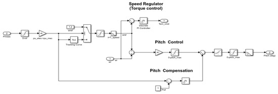
Figure 8.
Block diagram of the pitch angle control system in variable-speed wind turbines.
The speed regulator is implemented using a PI controller, which generates the reference torque command according to the following equation:
where e(t) = ωref − ωr is the speed error between the reference speed (ωref) and the measured rotor speed (ωr), while Kp and Ki are the PI controller gains. The electromagnetic torque is then regulated to follow the optimal power curve of the wind turbine:
where ρ is the air density, A is the swept area of the turbine blades, V is the wind speed, and Cp is the power coefficient, which depends on the tip-speed ratio λ and the pitch angle β. The pitch angle controller becomes active when the wind speed exceeds the rated value. It uses a PI controller to generate the pitch angle command β, which can be expressed as follows:
where ep(t) = Pref − Pout is the difference between the reference power and the actual output power.
Tem,ref(t) = Kp ∗ e(t) + Ki ∫ e(t) dt
Tem,ref = Pout/ωr = 0.5 ∗ ρ ∗ A ∗ Cp ∗ V^3/ωr
β(t) = Kpβ ∗ ep(t) + Kiβ ∫ ep(t) dt
It can be observed in Figure 9 that the maximum Cp is achieved at zero pitch angles, reaching approximately 0.48 at an optimal TSR (λ ≈ 8). As the pitch angle increases, both the peak value of Cp and the corresponding optimal λ decrease significantly, indicating reduced aerodynamic efficiency. This highlights the critical role of pitch control in limiting power capture during high wind speeds to protect the turbine and maintain stable operation.
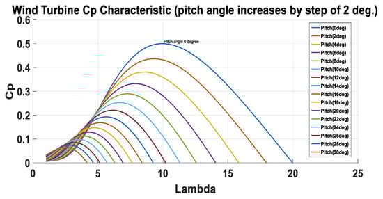
Figure 9.
Power coefficient (Cp) vs. tip speed ratio (λ) at different pitch angles.
4. System Modeling and Simulation
The effects of incorporating wind energy sources into preexisting grids are investigated by modeling and simulating a network consisting of a DFIG and a PMSG connected to a grid network. Two models of WECSs are developed: one based on a DFIG and the other on a PMSG. The rated output of the turbine is first achieved by simulating a constant wind speed of 15 m/s, and then the effects of varying wind speeds on the turbine output are studied by simulating a range of wind speeds. To enhance FRT capability and improve transient performance, a DC-link braking chopper is integrated into both models to dissipate excess energy and maintain voltage stability. Moreover, the system performance is evaluated under different types of grid faults, including single line-to-ground, line-to-line, and three-phase faults. The LVRT capability of each system was further assessed by comparing the simulated voltage profile with the ENTSO-E LVRT requirement curve [43,44]. This section outlines the modeling and simulation of DFIG and PMSG wind turbines in MATLAB/SIMULINK Version R2021a under four grid-connected scenarios:
- Constant Wind Speed Operation (15 m/s):The baseline performance of both generators was analyzed at rated wind speed, focusing on active and reactive power, rotor speed, and DC-link voltage stability.
- Variable Wind Speed Operation:The system response to fluctuating wind speeds was evaluated, highlighting differences in dynamic stability, pitch angle adaptation, and power regulation between the DFIG and the PMSG. The wind speed was kept constant at 15 m/s from 0 to 10 s, and then increased to 18 m/s from 10 to 25 s.
- Steady-State Performance under Normal Conditions:The impact of wind speed variations on grid parameters during normal operation was studied to establish reference behavior for both generator technologies.
- FRT under Grid Disturbances:A dynamic simulation was performed by introducing three fault types—single line to ground (SLG), line-to-line (LL), and three-phase (3Φ) faults at the bus B25 connected to the transmission line, cleared after 0.15 s. The investigation considered the role of the DC-link braking chopper in suppressing overvoltage transients and improving recovery performance for both the DFIG and the PMSG.
4.1. Model Description for DFIG
The simulated system is based on a detailed model of a DFIG wind turbine connected to the grid using MATLAB/Simulink. The test network consists of the following: Grid connection: A 120 kV infinite bus linked through 30 km, 25 kV transmission feeders. Wind farm configuration: The DFIG unit represents a 10 MW wind farm composed of five turbines, each rated at 2 MW. Local loads: At bus B25, a 1.68 MW induction motor (0.93 power factor) and a 200 kW resistive load are connected to a 2.3 kV, 2 MVA distribution system. DFIG machine: Modeled as a wound-rotor induction generator with stator windings directly connected to the grid, while rotor windings are interfaced through a back-to-back IGBT-based PWM AC/DC/AC converter. DC-link capacitor and braking chopper: Stabilize the DC voltage and dissipate excess energy during grid faults to enhance FRT capability. Operating modes: The turbine runs sub-synchronously at wind speeds below 10 m/s and super-synchronously at higher speeds, ensuring optimal energy capture.
4.2. Model Description for PMSG
The second system is based on a detailed model of a PMSG wind turbine implemented in MATLAB/Simulink, directly connected to the grid through a full-scale back-to-back converter. The test network is configured as follows: Grid connection: A 120 kV infinite bus interfaced through a 30 km, 25 kV transmission line. Wind farm configuration: The PMSG unit represents a 10 MW wind farm composed of five direct-drive turbines, each rated at 2 MW. PMSG machine: A PMSG operating at variable speed, eliminating the need for external excitation and slip rings. MSC: Regulates generator torque and speed, providing maximum power point tracking (MPPT) under varying wind speeds. GSC: Maintains constant DC-link voltage and injects active and reactive power to the grid with unity or controlled power factor. DC-link capacitor and braking chopper: Stabilize the DC voltage and suppress overvoltage during grid faults, enhancing FRT performance.
4.3. Control Loop Parameters and Settings
The control parameters listed in Table 1 were carefully selected to ensure stable and consistent performance for both DFIG- and PMSG-based WECSs under identical operating conditions. The PI gains and bandwidths were tuned to achieve fast dynamic response and minimal overshoot in current and voltage control loops. Identical sampling times, current/voltage limits, and PLL settings were applied to both systems to guarantee a fair and reliable comparison of their transient and steady-state behaviors.

Table 1.
Control parameters of DFIG and PMSG systems.
4.4. DC-Link Modeling and Parameter Definition
The DC-link circuit plays a vital role in ensuring stable operation of the converter by maintaining a constant voltage level and protecting the system from transient overvoltages. The detailed parameters of the DC-link, including the capacitance, chopper resistance, and voltage thresholds, are summarized in Table 2. These parameters were consistently applied to both the DFIG- and PMSG-based wind energy systems to ensure a fair and meaningful comparison of their DC-link voltage dynamics under identical operating conditions.
Table 2.
DC-link parameters used in the simulation model.
5. Results and Discussions
The detailed parameters of both machines are listed in Table 3 to facilitate reproducibility of the simulation results and provide a transparent basis for comparison.
Table 3.
Comparative parameters.
5.1. Normal Operation Characteristics of DFIG and PMSG at Constant Speed 15 m/s
Figure 10 illustrates the active power responses of the PMSG- and DFIG-based wind turbines under a constant wind speed of 15 m/s. At the initial stage, the DFIG output rises sharply to nearly 13.5 MW and undergoes damped oscillations between 6 and 12 MW before converging to the steady-state value of 10 MW within about 3 s. On the other hand, the PMSG peaks smoothly at around 12.5 MW and stabilizes at the same steady-state value of 10 MW within nearly 1 s. This behavior is due to the different converter topologies: The PMSG exhibits a faster and smoother dynamic response with reduced oscillations, which is attributed to the full-scale converter allowing for precise current control and decoupled power regulation. In contrast, the DFIG demonstrates more pronounced oscillatory behavior during the initial few seconds following the wind turbine start-up, owing to the partial-scale converter and the direct coupling of the stator to the grid.
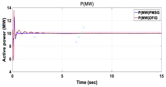
Figure 10.
Active power of DFIG and PMSG.
Figure 11 shows the reactive power responses of the PMSG- and DFIG-based wind turbines under a constant wind speed of 15 m/s. At the beginning, the DFIG exhibits a sharp overshoot reaching about +5 MVAR followed by a negative dip of −2 MVAR, before settling close to zero after approximately 1 s. In contrast, the PMSG peaks at around +1 MVAR and decays smoothly to zero within about 3 s. This indicates that the DFIG reaches steady state slightly faster but with stronger oscillations, whereas the PMSG shows a slower but smoother transition with better damping.
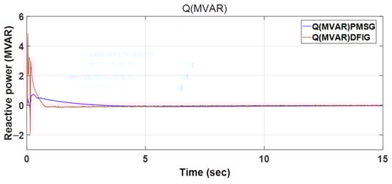
Figure 11.
Reactive power of DFIG and PMSG.
Figure 12 shows the rotor speed (in pu) for both the PMSG- and DFIG-based wind turbines at a fixed wind speed of 15 m/s. A clear difference in operating behavior can be observed between the two systems. The PMSG maintains a constant rotor speed close to its synchronous value (1 pu) throughout the simulation, reflecting the direct-drive configuration and the full-scale converter that fully decouples the generator from the grid. On the other hand, the DFIG operates at a super-synchronous speed (1.2 pu), as its stator is directly connected to the grid and only partially controlled via the rotor-side converter. The DFIG response also shows small oscillations in the initial seconds before settling, which are due to the coupling between the stator and grid voltage dynamics.
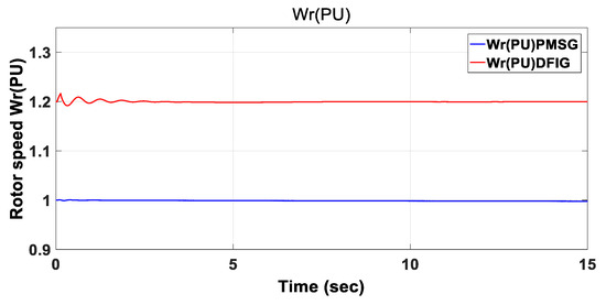
Figure 12.
Generator rotor speed of DFIG and PMSG.
Figure 13 shows the DC-link voltage profiles. The DFIG stabilizes at approximately 1150 V, reaching steady state within 0.15 s and showing only a small overshoot of about +3%. On the other hand, the PMSG settles at a slightly lower voltage of around 1100 V, but with a much higher overshoot, peaking near 1300 V (≈+18% above its steady-state value) and requiring around 0.6 s to stabilize. The difference in DC-link voltage dynamics can be attributed to the converter topology of each system. In the PMSG-based system, the use of a full-scale converter forces the entire generated power to pass through the DC-link, which increases its sensitivity to disturbances and leads to larger transient overshoots and longer settling times. In contrast, the DFIG employs a partial-scale converter, where a significant portion of the power is directly delivered through the stator. This reduces the stress on the DC-link, leading to faster stabilization and a smaller overshoot.
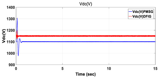
Figure 13.
Vdc link for DFIG and PMSG.
The pitch angle responses of the PMSG- and DFIG-based wind turbines under constant wind speed (15 m/s) are shown in Figure 14. The PMSG stabilizes faster with smaller oscillations, reaching a steady-state value of approximately 8.9°. In contrast, the DFIG exhibits larger oscillations, with an overshoot exceeding 9.5°, before gradually settling around 8.7°. The difference in transient behavior is due to the converter topology: the PMSG provides smoother control of the pitch system, while the DFIG leads to more oscillatory dynamics.
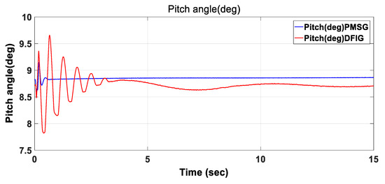
Figure 14.
Pitch angle at DFIG and PMSG.
5.2. Normal Operation Characteristics of DFIG and PMSG at Variable Wind Speeds
Time-Varying Wind Speed Profile
In order to evaluate the performance of the WECSs under dynamic wind conditions, a time-varying wind speed profile was applied to both configurations. As depicted in Figure 15, the wind speed was kept constant at 15 m/s from 0 to 10 s, and then increased to 18 m/s from 10 to 25 s. This change represents a high-wind operating condition, purposefully selected to emphasize the transient response of the systems and the DC-link voltage behavior under sudden wind fluctuations. Although a wind speed of 18 m/s exceeds the typical average for medium-wind sites, such a value effectively excites the system dynamics and highlights the robustness of the control and converter design. The same wind speed profile was consistently applied to both the DFIG and PMSG systems to ensure a fair and meaningful comparison of their transient and steady-state performance under identical external conditions.
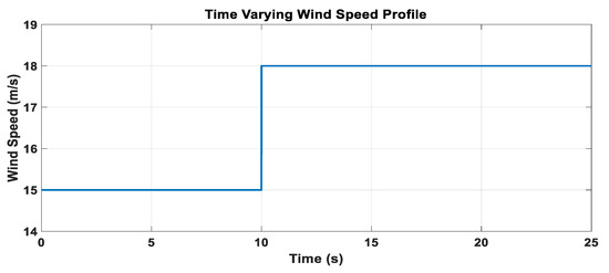
Figure 15.
Time-varying wind speed profile applied to both DFIG and PMSG systems.
To further evaluate the comparative performance of the DFIG- and PMSG-based WECSs, their responses under variable wind speed conditions are investigated. This analysis reflects the realistic operating environment of wind turbines, where wind speed fluctuations directly affect the electrical and mechanical dynamics of the system. The following results highlight the active and reactive power outputs, rotor speed variations, DC-link voltage behavior, and pitch angle adjustments for both generator types.
Figure 16 shows the active power responses of the DFIG- and PMSG-based wind turbines under variable wind speed operation. Initially, both systems stabilize around 10 MW, but when the wind speed increases at t = 10 s, the PMSG exhibits a faster rise with a peak of approximately 11.8 MW, whereas the DFIG reaches about 11.2 MW. Following the transient, the PMSG shows a smoother decline towards steady state, stabilizing near 10 MW by t = 20 s, while the DFIG experiences more pronounced oscillations and settles slightly below 10 MW. This behavior is primarily due to the converter configuration; the PMSG provides complete decoupling from the grid and enables finer power regulation, while the DFIG’s partial-scale converter and direct stator–grid coupling make it more vulnerable to wind speed fluctuations, in addition to the drivetrain structure, since the PMSG adopts a direct-drive scheme that reduces mechanical dynamics, while the DFIG employs a geared drive that introduces additional torsional oscillations reflected in the active power response.
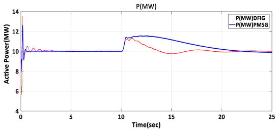
Figure 16.
Active power of DFIG and PMSG at variable speed.
Figure 17 compares the reactive power dynamics of both systems under variable wind speed. The DFIG exhibits a larger overshoot during startup (≈+4.5 Mvar) but settles to near zero more rapidly. In contrast, the PMSG shows a smaller overshoot (≈+0.5 Mvar) and a smoother response but requires slightly longer settling time before fully stabilizing near zero, consistent with the behaviors of their converter configuration.
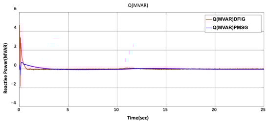
Figure 17.
Reactive power of DFIG and PMSG at variable speed.
Figure 18 shows the DC-link voltage response of DFIG and PMSG under variable wind speed with the integration of a DC-link chopper in both systems. The DFIG stabilizes around 1150 V with very small fluctuations, while the PMSG settles close to 1100 V. The inclusion of the DC-link chopper effectively suppresses the overvoltage spikes typically observed in PMSG, ensuring smooth stabilization for both systems. Consequently, the DC-link dynamics of the two systems become more comparable, although minor transient oscillations occur.
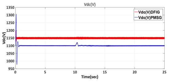
Figure 18.
Vdc for DFIG and PMSG at variable speed.
Figure 19 shows the rotor speed response of DFIG and PMSG under variable wind speed. The DFIG initially operates around 1.2 p.u. and exhibits noticeable oscillations, especially after the speed change at t = 10 s, before gradually stabilizing. In contrast, the PMSG starts at 1.0 p.u. and rises smoothly to about 1.12 p.u., followed by a slow decline toward steady state.
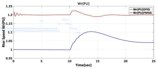
Figure 19.
Generator rotor speed of DFIG and PMSG at variable speed.
Figure 20 illustrates the pitch angle response of DFIG and PMSG under variable wind speed. Before t = 10 s, both systems remain nearly constant at around 9°. After the speed change, the DFIG shows a sharp rise, peaking near 16° with oscillations before settling, while the PMSG increases more gradually to about 15°. This indicates that the DFIG reacts faster but with larger overshoot, whereas the PMSG provides a smoother and more stable adjustment.
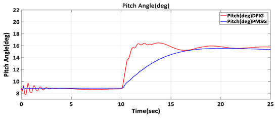
Figure 20.
Pitch angle of DFIG and PMSG at variable speed.
5.3. Comparative Analysis of PMSG and DFIG Wind Turbines Under Three-Phase Fault Conditions
This section examines the dynamic performance of wind turbines based on PMSGs and DFIGs when three-phase fault conditions are present. In this study, we compare the two systems’ reactive and active power responses before, during, and after the fault occurred. In contemporary wind energy applications, assessing the stability, control strategy, and FRT capabilities of different generator types requires a thorough understanding of these behaviors. To enhance the FRT analysis, a DC-link chopper was incorporated into the PMSG and DFIG model. This device prevents excessive DC-link voltage rise during grid faults, ensuring stable operation and compliance with grid code requirements.
Fault Implementation and System Parameters
The network parameters, including transmission line, transformer, and load data, are summarized in Table 4.
Table 4.
System and fault parameters used in the simulation.
Faults were implemented in MATLAB/Simulink using the three-phase fault block from the Simscape power systems library. Different fault types (SLG, L-L, and three-phase faults) were applied at (Bus B25) with a fault resistance of 0.1. The inception angle was set to 5.5°, and the faults were initiated at 15 s and cleared after 0.15 s by automatic circuit breaker operation. The block parameters were adjusted according to Table 4 and all components were modeled with their nominal ratings and per-unit impedances to ensure consistency in the comparison between the DFIG and PMSG systems.
Figure 21 shows the active power response of the DFIG and the PMSG under a three-phase fault applied at t = 15 s for 0.15 s. At the fault onset, the DFIG exhibits a higher transient peak of approximately 12.0 MW, while the PMSG reaches about 11.0 MW. Following fault clearance, both systems return to their steady-state operating point of 10.0 MW; however, the PMSG achieves steady state faster than the DFIG, which takes until roughly t ≈ 19 s to fully stabilize. The inclusion of DC-link choppers in both systems significantly reduces post-fault overshoot and enhances damping compared to the initial case without choppers.
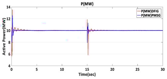
Figure 21.
Active power of DFIG and PMSG under three-phase fault.
Figure 22 illustrates the reactive power response of the DFIG and the PMSG during a three-phase fault with the integration of a DC-link chopper. The DFIG exhibits an overshoot from 0 to +3.5 Mvar, reflecting its ability to inject reactive power rapidly through the partial-scale converter, which enhances voltage support and meets LVRT requirements. Conversely, the PMSG response evolves from −2.5 to +2.5 Mvar, indicating a smoother but less aggressive compensation enabled by the full-scale converter. It can be observed that the DFIG stabilizes faster, returning to 0 Mvar after fault clearance, whereas the PMSG requires a slightly longer recovery time. The presence of the DC-link chopper plays a crucial role in suppressing excessive oscillations and stabilizing the DC-link voltage, thereby improving the dynamic reactive power capability of both systems. This behavior indicates that while both generators contribute to grid support during LVRT events, the DFIG provides a more aggressive reactive power injection, whereas the PMSG ensures a more stable and controlled recovery.
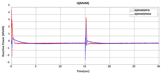
Figure 22.
Reactive power of DFIG and PMSG under three-phase fault.
Figure 23 shows the DC-link voltage response of DFIG and PMSG under a three-phase fault with a DC-link chopper integrated into both systems. During the fault, the chopper successfully limited the voltage overshoot. The DFIG exhibited a peak of about 1190 V, representing an increase of roughly 3.5% above its nominal value (1150 V), while the PMSG peaked near 1160 V, about 5.5% above its nominal value (1100 V). After fault clearance, both systems stabilized quickly at their respective steady-state levels. These results confirm that the DFIG achieves faster stabilization and reduced overvoltage stress, demonstrating better compliance with grid code requirements. These controlled deviations remain within the allowable limits of standard grid codes, highlighting the chopper’s effectiveness in suppressing overvoltage and ensuring compliance.
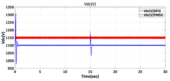
Figure 23.
Vdc for DFIG and PMSG under three-phase fault.
Figure 24 illustrates the generator rotor speed of the DFIG and the PMSG under a three-phase fault. The PMSG demonstrates a faster stabilization, while the DFIG shows small oscillations and requires a longer time to settle around its nominal value.
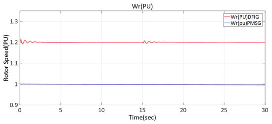
Figure 24.
Generator rotor speed of DFIG and PMSG under three-phase fault.
Figure 25 illustrates the pitch angle response of the DFIG and the PMSG under a three-phase fault. The PMSG shows a more stable and smoother pitch angle with minimal oscillations, whereas the DFIG experiences noticeable oscillatory behavior during and immediately after the fault. This indicates that the pitch control in the PMSG provides better damping and faster stabilization compared to the DFIG.
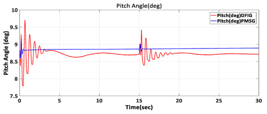
Figure 25.
Pitch angle for the DFIG and the PMSG under three-phase fault.
Figure 26 and Figure 27 show the three-phase terminal voltages (Vabc, p.u.) at Bus 25 of the DFIG and the PMSG during a three-phase fault. Both systems exhibit a transient voltage sag and temporary waveform distortion during the fault interval, followed by restoration to near-sinusoidal operation after fault clearance. The inclusion of DC-link choppers reduces DC-link excursions and aids converter recovery. This indicates the effectiveness of the FRT capability and the role of the DC-link chopper in mitigating severe overvoltage transients.
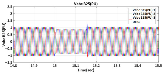
Figure 26.
Vabc_B25 (pu) at DFIG under three-phase fault.
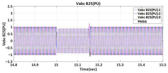
Figure 27.
Vabc_B25 (pu) at PMSG under three-phase fault.
Figure 28 and Figure 29 illustrate the three-phase current response (Iabc_B25) of the DFIG and the PMSG under a three-phase fault. At the fault inception (t = 15 s), both systems experience a sharp rise in current magnitude as a result of the voltage drop. With the integration of the DC-link chopper, the overcurrent is effectively limited, and after fault clearance (t ≈ 15.15 s), the currents smoothly return to their pre-fault steady-state values. This behavior demonstrates the capability of both wind energy systems to withstand grid disturbances and comply with LVRT requirements, as specified by standard grid codes.
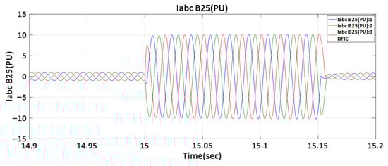
Figure 28.
Iabc_B25 (pu) at DFIG under a three-phase fault.
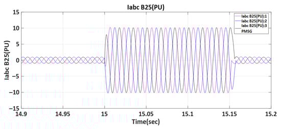
Figure 29.
Iabc_B25 (pu) at PMSG under a three-phase fault.
5.4. Comparative Analysis of PMSG and DFIG Wind Turbines Under Line-to-Line Fault Conditions
The simulation results under a line-to-line (L–L) fault, as shown in Figure 30, Figure 31, Figure 32, Figure 33, Figure 34, Figure 35, Figure 36, Figure 37 and Figure 38, exhibit similar dynamic patterns to those observed in the three-phase fault scenario, with notable differences in the severity of the transient responses. In particular, both the DFIG and the PMSG experience reductions in active power, rotor speed fluctuations, and DC-link voltage deviations during the fault interval; however, the overshoot and oscillation magnitudes are significantly lower compared to the three-phase case. This indicates that the L–L fault imposes less stress on the systems, which is consistent with theoretical expectations since the disturbance involves fewer phases. With the integration of the DC-link chopper, voltage excursions remain within acceptable limits, improving compliance with LVRT grid code requirements.
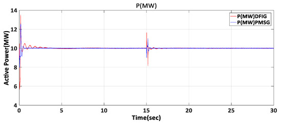
Figure 30.
Active power of DFIG and PMSG under line-to-line fault.
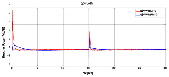
Figure 31.
Reactive power of DFIG and PMSG under line-to-line fault.
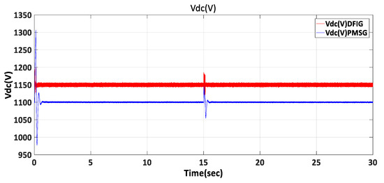
Figure 32.
Vdc for DFIG and PMSG under line-to-line fault.
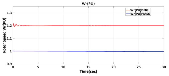
Figure 33.
Generator rotor speed of DFIG and PMSG under line-to-line fault.
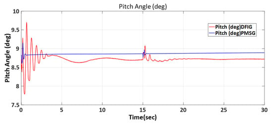
Figure 34.
Pitch angle for DFIG and PMSG under line-to-line fault.
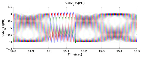
Figure 35.
Vabc_B25 (pu) at DFIG under line-to-line fault.
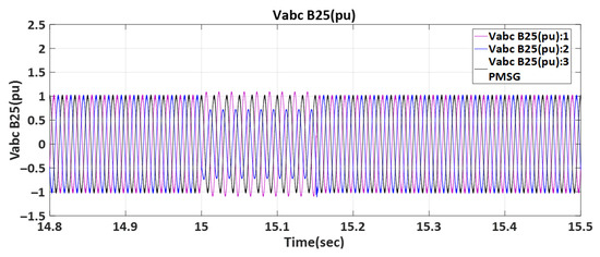
Figure 36.
Vabc_B25 (pu) at PMSG under line-to-line fault.
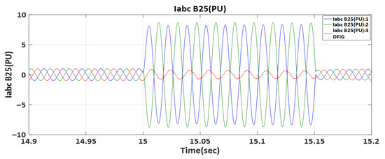
Figure 37.
Iabc_B25 (pu) at DFIG under line-to-line fault.
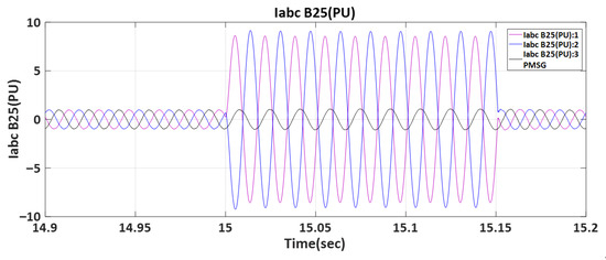
Figure 38.
Iabc_B25 (pu) at PMSG under line-to-line fault.
5.5. Verification of LVRT Compliance
To ensure a realistic evaluation of the system’s FRT capability, the simulation results were assessed against the ENTSO-E grid code requirements for LVRT [45]. According to the ENTSO-E LVRT specification, a generating unit must remain connected when the point of common coupling (PCC, bus 575) voltage does not fall below (0.05–0.3 p.u.) for a duration of (0.14–0.25 s), and the voltage should recover above 0.90 p.u. within 1 s after the fault is cleared. Both the DFIG- and PMSG-based systems were therefore evaluated by overlaying the ENTSO-E voltage–time curve on the simulated terminal voltage profiles. In addition, the reactive current responses were also included to further validate compliance with the ENTSO-E grid code. The comparison confirms that both systems successfully meet the LVRT criteria.
Figure 39 presents the RMS voltage at the PCC for the DFIG system during a three-phase fault initiated at t = 15 s and cleared after 0.15 s. The PCC voltage dropped from 1.00 p.u. to approximately 0.8 p.u. during the fault period and then recovered to 0.99 p.u. within 0.25 s after fault clearance. The simulated voltage profile remained fully within the ENTSO-E LVRT envelope, confirming that the DFIG control strategy successfully maintained grid connection and satisfied the voltage recovery requirements.
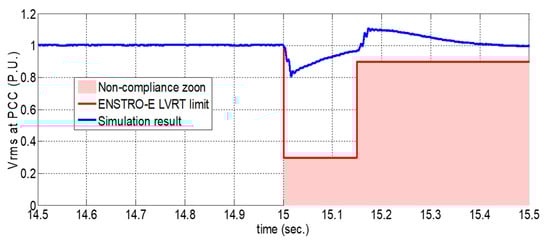
Figure 39.
LVRT performance of the DFIG system during the three-phase fault.
As shown in Figure 40, The ENTSO-E standard (red curve) indicates the required reactive current injection when the PCC voltage falls below 0.3 p.u., whereas the simulated result (blue trace) remained nearly zero with ripples. The PCC voltage did not fall below 0.8 p.u. and recovered rapidly to 0.99 p.u. within 0.25 s after fault clearance. This behavior confirms that the PCC voltage did not reach the activation threshold defined by the grid code. The DC-link braking chopper effectively dissipated excess energy and stabilized the DC-link voltage, preventing deeper voltage sag and eliminating the need for additional reactive current injection. As a result, the DFIG system maintained stable operation and complied with the ENTSO-E LVRT requirements.
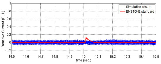
Figure 40.
Reactive current response of the DFIG during the three-phase fault.
Figure 41 shows the RMS voltage at the PCC for the PMSG system during a three-phase fault initiated at t = 15 s and cleared after 0.15 s. The PCC voltage decreased from 1.00 p.u. to about 0.80 p.u. during the fault interval and then recovered rapidly to 0.99 p.u. within 0.05 s after fault clearance. The simulated voltage profile remained within the ENTSO-E LVRT envelope, confirming that the PMSG control system maintained grid connection and enabled faster voltage recovery compared with the DFIG system.
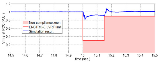
Figure 41.
LVRT performance of the PMSG system during a three-phase fault.
As illustrated in Figure 42, the reactive current remained nearly zero with ripples, indicating that the PCC voltage did not fall below 0.8 p.u. and recovered rapidly to 0.99 p.u. within 0.10 s after fault clearance. This confirms that the voltage level did not reach the threshold that necessitates reactive current injection according to the grid code requirements. This behavior is consistent with the expected performance of a full-scale converter-based PMSG equipped with a DC-link braking chopper, which dissipates excess energy, stabilizes the DC-link voltage, and prevents deep voltage sags. Consequently, the system maintained steady current conditions and exhibited superior dynamic stability and FRT performance during and after the disturbance.
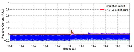
Figure 42.
Reactive current response of the PMSG during the three-phase fault compared with the ENTSO-E standard.
The comparative analysis summarized in Table 5 demonstrates that fault severity directly affects transient overshoot and recovery times. While three-phase faults impose the greatest stress, single-line faults cause minimal disturbances. The integration of the DC-link chopper ensured that voltage excursions in all cases remained within acceptable LVRT grid code limits.
Table 5.
Comparative summary of system responses under different fault types.
In addition to the obtained results, it is worth noting that recent studies have demonstrated the effectiveness of combining experimental validation with computational fluid dynamics (CFD) to achieve a more comprehensive understanding of turbine hydrodynamics and performance under different flow conditions.
For example, Ghamati et al. [45] presented an experimental and CFD-based analysis of the influence of flow velocity and submerged depth on tidal turbine performance, showing that the submergence depth significantly affects turbine efficiency and wake structure.
Although the present study focuses on wind turbines rather than tidal devices, incorporating similar CFD-based methodologies in future research could enhance aerodynamic validation and further support the comparative analysis of DFIG and PMSG systems.
6. Conclusions
This study presented a comparative performance evaluation of WECSs based on DFIG and PMSG under various operating conditions, including normal operation at constant and variable wind speeds, as well as under different grid fault scenarios. Detailed MATLAB/Simulink models were developed and improved by integrating a DC-link chopper in both systems to mitigate overvoltage stress and enhance compliance with LVRT requirements. The simulation results revealed that under normal and variable wind speeds, both systems achieve nearly the same steady-state active power output (~10 MW), though their dynamic characteristics differ. The PMSG exhibited smoother transient responses with reduced oscillations, whereas the DFIG demonstrated faster stabilization due to its partial-scale converter topology. Under fault conditions, the DC-link chopper effectively limited voltage overshoot, ensuring adherence to grid code safety margins. The DFIG shows advantages in reactive power support and faster stabilization, making it more robust under strict grid code requirements, while the PMSG offers smoother dynamic performance and a direct-drive configuration that eliminates gearbox-related mechanical issues. The comparative analysis under FRT conditions indicates that the DFIG provides faster reactive power recovery, making it more suitable for strict grid code compliance. In contrast, the PMSG exhibits smoother rotor dynamics with lower oscillations, ensuring superior transient stability. Therefore, the choice between DFIG and PMSG depends on whether the design priority is rapid voltage support or enhanced dynamic stability.
7. Future Work
Future work will focus on experimental validation and hardware-in-the-loop (HIL) implementation to further strengthen the reliability and applicability of the obtained results. In addition, the study will be extended to include the effects of frequency deviations, parameter uncertainties, and drivetrain dynamics to provide a more realistic evaluation of system performance under dynamic operating conditions. A detailed efficiency-based and techno-economic analysis will also be carried out to compare the overall energy conversion efficiency, cost, and long-term reliability of DFIG- and PMSG-based wind turbine systems. Such comprehensive investigations are expected to enhance the practical relevance and robustness of the proposed comparative framework.
Author Contributions
A.E.E. collected the data and prepared the initial draft. A.S.S. developed the simulation models and performed data analysis. A.H.A. contributed to the methodology and interpreted the results. A.S.N. supervised the work, revised the manuscript, and approved the final version. All authors have read and agreed to the published version of the manuscript.
Funding
This research received no external funding, and the APC was not funded by any external organization.
Institutional Review Board Statement
Not applicable.
Informed Consent Statement
Not applicable.
Data Availability Statement
The data that support the findings of this study were generated using MATLAB/Simulink simulations. The data are available from the corresponding author upon reasonable request.
Acknowledgments
The authors would like to express their sincere gratitude to the Faculty of Engineering, Al-Azhar University, Cairo, Egypt, for the continuous support and encouragement throughout this research. Special thanks are extended to the department staff for providing the necessary resources and academic environment to complete this work.
Conflicts of Interest
The authors declare no potential conflicts of interest regarding the publication of this work. In addition, the ethical issues including plagiarism, informed consent, misconduct, data fabrication and/or falsification, double publication and/or submission, and redundancy have been thoroughly checked for by the authors.
Nomenclature
| Symbol | Description |
| Vs | Stator voltage (V) |
| Is | Stator current (A) |
| Vr | Rotor voltage (V) |
| Ir | Rotor current (A) |
| P | Output active power (MW) |
| Q | Output reactive power (MVAR) |
| wr | Rotor angular speed (rad/s) |
| Te | Electromagnetic torque (N·m) |
| Air density | |
| power coefficient | |
| TSR, λ | Tip Speed Ratio |
| DFIG | Doubly-Fed Induction Generator |
| PMSG | Permanent Magnet Synchronous Generator |
| LVRT | Low Voltage Ride-Through |
| FRT | Fault Ride-Through |
| WECS | Wind Energy Conversion System |
| MSC | Machine-Side Converter |
| GSC | Grid-Side Converter |
| VSC | Voltage source converter |
| PLL | Phase-Locked Loop |
| RSC | Rotor-side converter |
| Β | Blade pitch angle |
| PI | Proportional–Integral |
| Vdc | DC link voltage |
References
- Global Wind Energy Council. Global Wind Report 2024; GWEC: Lisbon, Portugal, 2024. [Google Scholar]
- Chen, Y.; Pillay, P. Comparative Study of Wind Turbine Generator Systems. IEEE Trans. Energy Convers. 2022, 23, 544–550. [Google Scholar]
- Ghandhari, M. DFIG Wind Turbine Performance during Grid Disturbances. Electr. Power Syst. Res. 2021, 200, 107491. [Google Scholar]
- Al-Wash, S.M.; Al-Thahab, O.Q.; Al-Wash, S. A Review of Control Techniques and Future Trends in Wind Energy Turbine Systems with Doubly Fed Induction Generators (DFIG). J. Univ. Babylon Eng. Sci. 2023, 31, 32–50. [Google Scholar]
- Gangikunta, M.; Venkateshwarlu, S.; Laxmi, A.J. Comparative Analysis of Low Voltage Ride Through Techniques of DFIG Connected to Grid using AI Techniques. E3S Web Conf. 2024, 472, 01002. [Google Scholar] [CrossRef]
- Rani, S.B.; Singh, B. Full-Scale Converter Control of PMSG Wind Turbines for Enhanced Grid Compliance. IET Renew. Power Gener. 2023, 17, 122–134. [Google Scholar]
- Rajendran, S.; Diaz, M.; Cárdenas, R.; Espina, E.; Contreras, E.; Rodriguez, J. A Review of Generators and Power Converters for Multi-MW Wind Energy Conversion Systems. Processes 2022, 10, 2302. [Google Scholar] [CrossRef]
- Bortolotti, P.; Barter, G.; Sethuraman, L.; Keller, J. A Comparison of Generator Technologies for Offshore Wind Turbines. NREL Report, 2023, NREL/PR-85341. Available online: https://www.nrel.gov/docs/fy23osti/85341.pdf (accessed on 26 September 2025).
- Mostafa, M.A.; El Hay, E.A.; Elkholy, M.M. An Overview and Case Study of Recent Low Voltage Ride Through Methods for Wind Energy Conversion System. Renew. Sustain. Energy Rev. 2023, 183, 113521. [Google Scholar] [CrossRef]
- Shabani, H.R.; Hajizadeh, A.; Kalantar, M.; Lashgari, M.; Nozarian, M. Transient stability analysis of DFIG-based wind farm-integrated power system considering gearbox ratio and reactive power control. Electr. Eng. 2023, 105, 3719–3735. [Google Scholar] [CrossRef]
- Al-Khatib, R.; Ahmed, K.; El-Sayed, H. MPPT Control of Grid Connected DFIG at Variable Wind Speed. Energies 2022, 15, 3146. [Google Scholar] [CrossRef]
- Khaled, M.; Ahmed, M.K.; Elwany, M.; Shalaby, M. MPPT of Small Wind Turbine Direct-Drives Axial Flux Permanent Magnet Synchronous Generator. J. Al-Azhar Univ. Eng. Sect. 2019, 14, 968–981. [Google Scholar] [CrossRef]
- Abdalla, M.; Hassan, M.; Mahmoud, M.; Elshaer, H. A scientometric analysis on DFIG-based wind energy conversion system research trends. Discov. Appl. Sci. 2024, 7, 7. [Google Scholar] [CrossRef]
- Mahmoud, M.M.; Atia, B.S.; Abdelaziz, A.Y.; Aldin, N.A.N. Dynamic Performance Assessment of PMSG and DFIG-Based WECS with the Support of Manta Ray Foraging Optimizer Considering MPPT, Pitch Control, and FRT Capability Issues. Processes 2022, 10, 2723. [Google Scholar] [CrossRef]
- Alepuz, S.; Busquets-Monge, S.; Bordonau, J.; Martinez-Velasco, J.A.; Silva, C.A.; Pontt, J.; Rodriguez, J. Control strategies based on symmetrical components for grid-connected converters under voltage dips. IEEE Trans. Ind. Electron. 2009, 56, 2162–2173. [Google Scholar] [CrossRef]
- Moustafa, R.M. Ahmed El Biomy Mansour, Abd El Ghany Mohammed Voltage Recovery Control Techniques of Grid Connected Variable Speed Wind Turbines a t a Short Circuit. Int. J. Recent Technol. Eng. 2019, 8, 868–873. [Google Scholar]
- Abdeen, M.; Al Dawsari, S.; El-Dabah, M.A.; Ahmed, M.K.; Touti, E.; Diab, A.A.Z.; Abo El-Magd, A.G. Doubly Fed Induction Generator Frequency Regulation Enhancement Using Combined Inertia and Proportional Resonant Controller. Processes 2025, 13, 1284. [Google Scholar] [CrossRef]
- Kadoche, E.; Bianchi, P.; Carton, F.; Ciblat, P.; Ernst, D. How to craft a deep reinforcement learning policy for wind farm flow control. arXiv 2025. [Google Scholar] [CrossRef]
- Xu, L.; Wang, Y. Dynamic modeling and control of DFIG-based wind turbines under unbalanced network conditions. IEEE Trans. Power Syst. 2007, 22, 314–323. [Google Scholar] [CrossRef]
- Jiang, K.; Li, L.; He, Z.; Liu, D. Stability Limit Analysis of DFIG Connected to Weak Grid in DC-Link Voltage Control Timescale. Electronics 2025, 14, 3022. [Google Scholar] [CrossRef]
- Okedu, K.E.; Muyeen, S.M. Comparative Performance of DFIG and PMSG Wind Turbines during Transient State in Weak and Strong Grid Conditions Considering Series Dynamic Braking Resistor. Energies 2022, 15, 9228. [Google Scholar] [CrossRef]
- Abu-Rub, H.; Malinowski, M.; Al-Haddad, K. Power Electronics for Renewable Energy Systems, Transportation and Industrial Applications; Wiley: Hoboken, NJ, USA, 2014. [Google Scholar]
- Dani, A.; Benlamlih, M.; Mekrini, Z.; El Mrabet, M.; Boulaala, M. Wind Energy Conversion Technologies and Control Strategies: A Review. Int. J. Renew. Energy Res. 2024, 14, 140–154. [Google Scholar]
- Abo-Alela, S.A.-Z. Design And Performance of Hybrid Wind-Solar Energy Generation System for Efficiency Improvement. J. Al Azhar Univ. Eng. Sect. 2018, 13, 1118–1124. [Google Scholar] [CrossRef]
- Okedu, K.E.; Al Tobi, M.; Al Araimi, S. Comparative Study of the Effects of Machine Parameters on DFIG and PMSG Variable Speed Wind Turbines During Grid Fault. Front. Energy Res. J. 2021, 9, 681443. [Google Scholar] [CrossRef]
- Yahyaoui, I. Advances in Renewable Energies and Power Technologies; Elsevier: Amsterdam, The Netherlands, 2018; Volume 1. [Google Scholar]
- Prajzendanc, P.; Kreischer, C. A Review of New Technologies in the Design and Application of Wind Turbine Generators. Energies 2025, 18, 4082. [Google Scholar] [CrossRef]
- Sreenivasulu, S.; Hussain, J. Protection of rotor side converter of DFIG-based wind energy conversion system under symmetrical grid voltage fluctuations. Front. Energy Res. 2024, 12, 1465167. [Google Scholar] [CrossRef]
- Shi, S. A high robust control scheme of grid-side converter for DFIG system. IET Control Theory Appl. 2024, 18, 2277–2286. [Google Scholar] [CrossRef]
- El-Tawab, S.; Nassar, I.; Mehanna, M. Hybrid DFIG Driven Wind Turbine—Grid Systems Modeling and Control for Reliable Source. Int. J. Recent Technol. Eng. 2019, 8, 400–409. [Google Scholar] [CrossRef]
- Achar, A.; Djeriri, Y.; Benbouhenni, H.; Bouddou, R.; Elbarbary, Z.M.S. Modified Vector-Controlled DFIG Wind Energy System Using Robust Model Predictive Rotor Current Control. Arab. J. Sci. Eng. 2025, 50, 11065–11089. [Google Scholar] [CrossRef]
- Feddaoui, A.; Farah, L.; Benretem, A.; Djehaf, M.A.; Bouguerra, Z.; Djeriri, Y. Enhancing power control in doubly fed induction generator based wind turbines: A performance comparison of fuzzy logic and sliding mode control methods. Sci. Bull. Electr. Eng. Fac.-SBEEF. 2023, 23, 42–50. [Google Scholar] [CrossRef]
- Bouguettah, I.; Messadi, M.; Kemih, K.; Azar, A.T.; Mahlous, A.R. Adaptive passive fault tolerant control of DFIG-based wind turbine using a self-tuning fractional integral sliding mode control. Front. Energy Res. 2024, 12, 1429877. [Google Scholar] [CrossRef]
- Vadi, S.; Gürbüz, F.B.; Gürbüz, B.R.; Hossain, E. Design and Simulation of a Grid Connected Wind Turbine with Permanent Magnet Synchronous Generator. In Proceedings of the 8th IEEE International Conference on Smart Grid (icSmartGrid), Paris, France, 17–19 June 2020; pp. 169–175. [Google Scholar]
- Behabtu, H.A.; Coosemans, T.; Berecibar, M.; Fante, K.A.; Kebede, A.A.; Van Mierlo, J.; Messagie, M. Performance Evaluation of Grid-Connected Wind Turbine Generators. Energies 2021, 14, 6807. [Google Scholar] [CrossRef]
- Vineet, D.; Leena, G. Comparative Study of Doubly Fed Induction Generator and Permanent Magnet Synchronous Generator in Wind Energy Conversion System. Int. J. Electr. Eng. Technol. 2019, 10, 73–79. [Google Scholar] [CrossRef]
- Li, S.; Haskew, T.A.; Swatloski, R.P.; Gathings, W. Optimal and direct-current vector control of direct-driven PMSG wind turbines. IEEE Trans. Power Electron. 2012, 27, 2325–2337. [Google Scholar] [CrossRef]
- Larabi, Z.; Ghedamsi, K.; Aouzellag, D. Direct Drive Permanent Magnet Synchronous Generator: Design, Modeling, and Control for Wind Energy Applications. Period. Polytech. Electr. Eng. Comput. Sci. 2024, 68, 168–177. [Google Scholar] [CrossRef]
- Zhou, Z.; Wang, S.; Jiang, J.; Li, H.; Zhao, J.; Yu, D. Optimizing wind turbine blade pitch control via input output model free adaptive control. Sci. Rep. 2025, 15, 6325. [Google Scholar] [CrossRef] [PubMed]
- Lyu, X.; Subotić, I.; Groß, D. Unified Grid-Forming Control of PMSG Wind Turbines for Fast Frequency Response and MPPT. arXiv 2022. [Google Scholar] [CrossRef]
- Elkattan, A.M.; Sokar, M.S.; Abdellatif, O.E. Investigating Robust Pitch Angle Control Techniques of the NREL 1.5 Mw HAWT. J. Al-Azhar Univ. Eng. Sect. 2025, 20, 211–227. [Google Scholar] [CrossRef]
- Singh, B.; Gupta, S.K.; Chatterjee, A. Power Electronics for Next Generation Drives and Energy Systems: Volume 2—Clean Generation and Power Grids; IET: London, UK, 2023; Available online: https://ebin.pub/power-electronics-for-next-generation-drives-and-energy-systems-volume-2-clean-generation-and-power-grids-1839534699-9781839534690.html (accessed on 26 September 2025).
- Khodakaramzadeh, S.; Ayati, M.; Haeri Yazdi, M.R. Fault diagnosis of a permanent magnet synchronous generator wind turbine. J. Electr. Comput. Eng. Innov. 2020, 9, 143–152. [Google Scholar]
- Johnson, A. (Ed.) Fault Ride Through ENTSO-E Requirements for Generators—Interpretation; National Grid: London, UK, 2015. [Google Scholar]
- Ghamati, E.; Kariman, H.; Hoseinzadeh, S. Experimental and computational fluid dynamic study of water flow and submerged depth effects on a tidal turbine performance. Water 2023, 15, 2312. [Google Scholar] [CrossRef]


Disclaimer/Publisher’s Note: The statements, opinions and data contained in all publications are solely those of the individual author(s) and contributor(s) and not of MDPI and/or the editor(s). MDPI and/or the editor(s) disclaim responsibility for any injury to people or property resulting from any ideas, methods, instructions or products referred to in the content. |
© 2025 by the authors. Licensee MDPI, Basel, Switzerland. This article is an open access article distributed under the terms and conditions of the Creative Commons Attribution (CC BY) license (https://creativecommons.org/licenses/by/4.0/).