Abstract
The scaling effect of machines from kW to MW greatly affects electromagnetic performance and needs to be investigated for different machines. Therefore, this paper presents a comprehensive comparative study on the intriguing electromagnetic performance of contra-rotating permanent-magnet vernier machines and dual-port, wound-field-excited, flux-switching machines at the MW power level for contra-rotating wind turbine applications. The analysis evaluates both machines across various slot/pole combinations while maintaining constant key design parameters. The electromagnetic performance analysis reveals that the permanent-magnet vernier machine (PMVM) exhibits superior torque and power, with minimal cogging torque compared to the wound-field flux-switching machine (WFFSM). Conversely, the WFFSM outperforms the PMVM in terms of power factor and efficiency. This study provides valuable perspectives on the strengths and weaknesses of each machine, highlighting their potential for contra-rotating turbine and wind power generation. Finally, to justify the findings of the finite element analysis and the proof of concept, an experimental prototype is tested to validate the study.
1. Introduction
Fossil fuels lead global energy consumption by 80%; hence, evolution from fossil fuels to clean energy is vital for addressing climate change, improving economic growth, and ensuring a sustainable future [1]. To provide sustainable energy solutions, significant contributions are being made by researchers in advancing clean energy technologies. Renewable energy sources like wind, solar, and hydropower are progressively being adopted to reduce dependence on fossil fuels. Wind power is a substantial contributor among other renewable energy sources, offering a key role in clean energy dynamics [2]. The shift towards wind power has brought high-torque, high-power-density wind-powered machines under much consideration [3]. Among many other wind-powered machines, vernier machines [4] and flux-switching machines [5] have high torque/power density, making them good choices for wind turbines. Several techniques for enhancing the conversion efficiency of wind energy to electrical energy are under consideration by researchers.
At present, contra-rotation, also termed counter-rotation, is considered an innovative approach in these types of wind-powered machines to enhance the electromagnetic performance of the designs. In this technique, the wind turbine is classified based on the direction of rotation and spinning rotor. In this type of wind turbine, there are two sets of rotors that rotate in contra-rotation with respect to each other. It is notable that, in contrast to contra-rotation, co-rotation is simply the rotation of both front and rear rotors in the same direction. Contra-rotating turbines do not require the use of gearboxes, which simplifies the mechanical structure while generating more power with high efficiency, structural stability, and low maintenance—making them a promising technology for sustainable wind energy production [6].
For wind power generation, contra-rotation is achieved by using a pair of wind blades connected back-to-back, rotating in opposite directions with respect to each other. The rotors of both machines under study are contra-rotating and are directly coupled with the respective shafts of wind turbines. Authors [7] compared the single-rotor turbine with the counter-rotating wind turbine, which increases power conversion efficiency by 40–50% from a fixed cross-sectional area [8,9].
There are different studies on contra-rotating, flux-switching machines for wind power generation. The studies are based on permanent-magnet and magnet-less or wound field flux-switching generators. For the permanent-magnet flux-switching generator, a comparative study of dual stator contra-rotating topology with dual rotor contra-rotating topology is made; the latter exhibits higher flux, suppressed cogging torque, and torque ripples, respectively. Furthermore, analysis under overload and overspeed reveals that the dual rotor contra-rotating topology has an improved voltage regulation factor while maintaining an efficiency of 90.2% and attaining a stable voltage profile with load variations.
To overcome the dire increase in rare-earth permanent-magnet cost, avoid the requirements of brushes and slip rings, and eliminate the gearbox mechanism, a magnet-less dual electrical and dual mechanical port wound field-excited flux-switching machine for direct-drive contra-rotating wind turbine applications is also proposed in [10,11,12]. When compared to co-rotation, the contra-rotation of rotors enhances the machine’s performance in terms of torque/power more than the co-rotation of rotors [11].
For vernier machines, to keep the machine’s volume unaffected, double stator/rotor concentric structures have been adopted in the literature for further enhancement of torque density. However, this increased torque density is achieved at the expense of structural complexity and higher copper consumption [13]. The proposed design in [14] has a single stator sandwiched between two rotors having slots on either side facing the rotors, and this design is taken as the base design for the permanent-magnet vernier machine in this study. The core is optimized by split-ratio optimization, and the cross-toroidal winding configuration is replaced by a concentrated winding configuration, while maintaining the design’s simplicity and compactness.
To summarize, the main contributions include the development of a contra-rotating permanent-magnet vernier machine (PMVM) and a wound-field-excited flux-switching machine (WFFSM) for direct-drive wind power applications; explicitly explained generalized mathematical sizing and relation of the performance metrics with slot/pole combinations; design selection of PMVM and WFFSM based on electromagnetic performance with variation in the slot/pole combination at MW power level; investigation of key performance trade-offs between PMVM and WFFSM at MW power level; and a comprehensive comparative study on highly efficient direct-drive wind-powered contra-rotating PMVM and dual-mechanical-port WFFSM at MW power level, as shown in Figure 1, accounting for electromagnetic performance, cost, and weight of the generators. Compared with conventional single-rotor wind power generators, the proposed PMVM and WFFSM exhibit superior performance in terms of torque/power density and energy efficiency and are considered promising candidates for gearless direct-drive wind power applications.
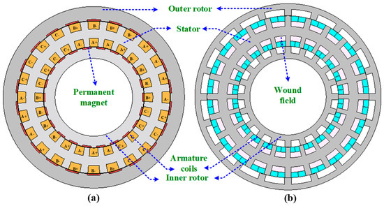
Figure 1.
Cross-sectional view of machine topology: (a) PMVM, and (b) WFFSM.
In the following section, Section 2 discusses the methodology, including mathematical sizing, machine topologies, and slot/pole combinations. A comprehensive performance comparison is carried out in Section 3 as results and discussion. To justify the FEA findings, a prototype is fabricated, and experimental verification is conducted in Section 4. Finally, some conclusions are drawn in Section 5.
2. Methodology
2.1. Mathematical Sizing
For the initial design purpose, at the preliminary stage, mathematical formulation has been adopted for the sizing of both PMVM and WFFSM. The focus in the sizing is on the slot/pole combination, which is the key factor in the electromagnetic performance analysis and comparison between the two variants of the aforementioned machines. Generally, sizing formulae are needed to determine an electric machine’s primary parameter sizes. Depending on the machine’s structure and working principle, the sizing formulae for various topologies vary and list of symbols for the sizing formulas can be found in Appendix A.
2.1.1. PMVM Mathematical Sizing
For PMVM, the electromagnetic torque variation with the given pole pair number (), current per phase (), and magnetic flux linage (), is expressed as:
where represents the phase number, and is the angle between the magnetic field and the current.
The magnetic flux linkage () for the number of turns per phase and winding factor () is computed by:
where is the flux per stator phase and calculated as:
where is the rotor pole arc, is the leakage factor, is the stator pole pair number, is the outer diameter of the rotor, is the stack length, and is the peak value of the inner air gap flux density.
In the electromagnetic torque expression, the per-phase current can be expressed as:
where is the electrical loading of the machine.
Using the expression for per-phase current and magnetic flux linkage, the electromagnetic torque can be rewritten as:
Based on the electromagnetic torque, electromagnetic power can be simplified as:
Regarding the slot/pole combination for PMVM, the following particular rule applies:
where, and rotor pole and stator slot number.
Selecting stator slot and rotor pole combinations, the stator MMF, i.e., , interacts with the magnet MMF fundamental component, i.e., the gear ratio (), in terms of the slot/pole’s combinations, is defined as:
where, is the rotor pole and i.e., , is the winding pole pair number. Based on the mathematical sizing, both the sizing and slot/pole combination are selected for the detailed analysis.
2.1.2. WFFSM Mathematical Sizing
For the WFFSM, the combination of the stator slot and rotor poles also determines the torque capabilities regardless of the winding layout and expressed as [14]:
where, and represent integer number and number of phases, respectively.
Among various slot/poles variants of WFFSM, the following criteria must be satisfied to achieve symmetrical back electromotive force (back-EMF):
and
When a brushless AC operates with symmetrical back-EMF, sinusoidal current, and flux linkage, the electromagnetic torque is given as:
where,
The torque expression is made simpler by taking into account the identical inductance in the d- and q-axes.
This clarifies that torque capability is mainly dependent on rotor pole number.
From the magnetic field distribution in the air gap, flux linkage, and back-EMF are also computed. In the air-gap region (), the flux linkage in terms of the air-gap magnetic flux density () is defined as:
Similarly, the maximum air-gap flux density ()-induced approximate sinusoidal back-EMF is represented as:
where,
and represents speed in rad/min.
Based on the simplified formulation, it is clear that, despite the q-axis current, torque depends on the rotor pole combinations. Using this formulation, various slot/pole combinations are derived for extensive analysis in the subsequent sections, utilizing the design methodology as displayed in Figure 2.
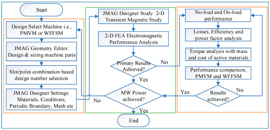
Figure 2.
Design methodology of MW-level comparative analysis.
The design methodology consists of a series of consecutive analyses, starting from the design selection and moving toward the FEA-based analysis to obtain the primary results at the MW power level. Once the power requirement criteria are met, the design is further evaluated through no-load and on-load comprehensive analysis and comparison between the two variants of the generator.
2.2. Machine Topologies and Slot/Poles Combinations
For large direct-drive wind-powered generators, the outer rotor topology is deemed superior due to its structural assembly advantages. This design facilitates the direct coupling of the generator rotor to the turbine blades, enabling a multi-pole structure to be implemented because of the large circumference. Consequently, this configuration significantly enhances torque density. Among different permanent-magnet vernier and flux-switching machine topologies, a contra-rotating dual-rotor PMVM and a dual electrical and dual mechanical port WFFSM, shown in Figure 1, have been chosen for this MW-level comparative study.
The contra-rotating PMVM topology consists of a dual consequent-pole rotor structure with a single stator positioned in between. The concentrated winding configuration is used in the stator slots for reduced copper consumption and enhanced efficiency. The WFFSM topology also consists of a single stator having dual non-overlapped single-tooth armature windings and a toroidal field winding around the stator yoke, positioned between the inner and outer rotors.
In contrast to conventional overlapped winding methods, the use of non-overlapped and toroidal windings reduces copper usage and enhances overall efficiency. With the dual electrical port configuration of the WFFSM, the inner and outer armatures remain isolated, allowing for independent outputs from each terminal. The electromagnetic performance analysis evaluates both machines across various slot/pole combinations, listed in Table 1, while maintaining constant key design parameters given in Table 2.

Table 1.
Slot/Pole Combination retrieved from mathematical sizing.
Table 2.
Key Parameters for PMVM and WFFSM.
The slot/pole numbers for the PMVM are chosen with an optimal gear ratio, i.e., , as it is a widely used gear ratio in the literature studies [15] to achieve good overall performance. A gear ratio of 5 represents a balanced relationship between the number of rotor pole pairs and stator winding pole pairs. This ratio optimizes the magnetic gearing effect, which enhances torque production. The proper selection of gear ratios is crucial for maximizing the electromagnetic performance of vernier machines [16]. This gear ratio strikes a good balance between speed and torque, leading to improved overall efficiency and performance characteristics. Moreover, helps to minimize losses associated with higher gear ratios, such as increased inductance and reduced power factor at excessively high ratios [17]. These machines are analyzed with different slot/pole number combinations, referred to as design numbers, and the performance summary for the optimal design 6 (for both machines) is given in Table 3.
Table 3.
Summary of Electromagnetic Performance at Design Number 6.
3. Results and Discussions
In the results and discussion, the electromagnetic performance of the contra-rotating PMVM and WFFSM is investigated using FEA, and the performance of both machines is evaluated in terms of no-load back-EMF, cogging torque, on-load torque/power, efficiency, and power factor on selected slot/pole combinations. The mass and cost of the machines are also evaluated for system-level comparison.
3.1. No-Load Back-EMF, Cogging Torque, and On-Load Torque
The no-load back-EMF values of the contra-rotating PMVM and WFFSM on different slot/pole number combinations, referred to as design numbers, are shown in Figure 3. The no-load back-EMF is significantly higher in the case of the PMVM because of the high flux concentration due to N35 permanent magnets. The maximum no-load back-EMF achieved in the case of the PMVM is much higher than that of the WFFSM. The higher no-load back-EMF in the PMVM results in superior on-load torque and power compared to the WFFSM, as shown in Figure 4 and Figure 5, respectively. The maximum value of on-load torque in the PMVM is 2393.780 kNm, resulting in 3.75 MW of power.
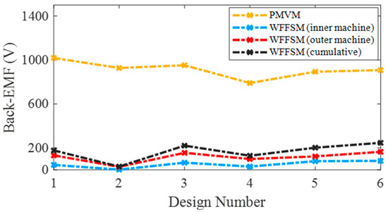
Figure 3.
No-load back-EMF comparison for PMVM and WFFSM.
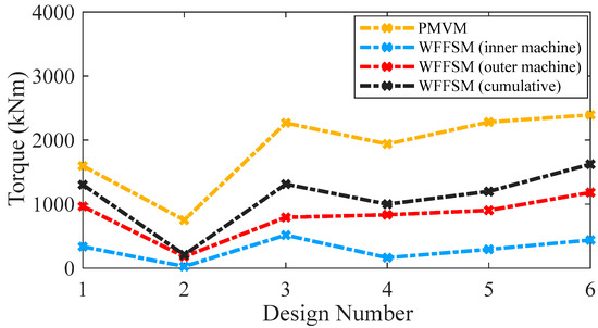
Figure 4.
On-load average torque comparison for PMVM and WFFSM.
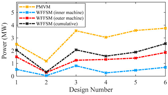
Figure 5.
Power comparison for PMVM and WFFSM.
On the other hand, the maximum on-load torque (cumulative) in the case of the WFFSM is 1624.38 kNm, resulting in 2.55 MW of power. The cogging torque ratio, i.e., [(ratio of peak-to-peak cogging torque to average torque) × 100], for the PMVM and WFFSM on selected slot/pole number combinations is listed in Table 4, which shows that the PMVM has significantly less cogging torque compared to the WFFSM. The optimum design of the PMVM has a cogging torque ratio of 8.96% for the inner rotor and 7.19% for the outer rotor. On the other hand, the optimum design of the WFFSM has a cogging torque ratio of 41.61% for the inner rotor and 42.63% for the outer rotor.
Table 4.
Percentage of Cogging Torque with Inner and Outer Rotor.
3.2. Losses and Efficiency
The PMVM has more iron losses compared to the WFFSM due to a larger core volume; however, the copper losses in the case of the PMVM are much lower than those of the WFFSM due to shorter winding end length. The WFFSM has higher copper losses due to the presence of field excitation in addition to the armature winding. The core and copper losses on selected slot/pole number combinations are shown in Figure 6 for both machines, whereas the efficiency of the PMVM and WFFSM (inner and outer machines) on selected slot/pole number combinations is shown in Figure 7. Both machines exhibit good efficiency, making them suitable for direct-drive wind-power applications. The optimum efficiency in the case of the PMVM is 95.92%, and in the case of the WFFSM, it is 98.66% and 99.31% for the inner and outer machines, respectively.
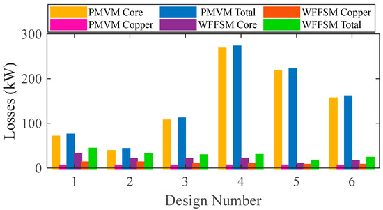
Figure 6.
Losses comparison for PMVM and WFFSM.
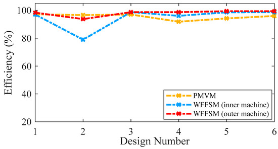
Figure 7.
Efficiency comparison for PMVM and WFFSM.
3.3. Power Factor
A power factor exceeding 0.9 stands as a pivotal requirement for optimal performance of a wind-powered generator. This comparative study of the PMVM and WFFSM at MW power level revealed some noteworthy insights. The comparison of the power factor between the PMVM and WFFSM for selected slot/pole number combinations is shown in Figure 8. Notably, the WFFSM exhibits an exceptional power factor of 0.99 for its inner machine and 0.97 for its outer machine. On the other hand, the PMVM also exhibits a high-power factor of 0.87. This comparative analysis highlights the superior power factor performance of both machines along with high efficiency.
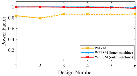
Figure 8.
Power factor comparison for PMVM and WFFSM.
3.4. Torque/Mass and Torque/Cost
The mass and cost analysis for the PMVM and WFFSM on selected slot/pole numbers is shown in Figure 9 and Figure 10, respectively. The analysis reveals that the PMVM has greater structural mass due to the permanent magnets, leading to a higher cost than the WFFSM. The PMVM exhibits a higher torque-to-mass ratio compared to the WFFSM, as indicated by the total mass and cost analysis on the optimal slot/pole number combination detailed in Table 5. Conversely, the WFFSM demonstrates a superior torque-to-cost ratio in comparison to the PMVM, as illustrated in the calculations based on the mass and cost of the generator’s active materials, depicted in Figure 11 and Figure 12, respectively.
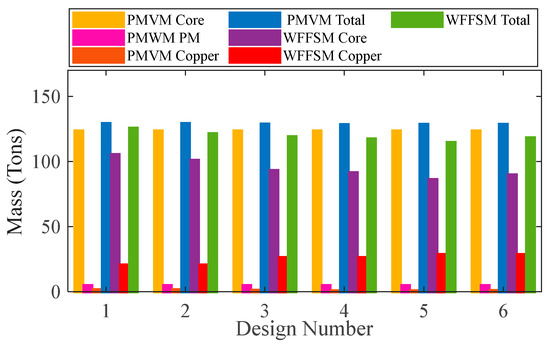
Figure 9.
Mass comparison for PMVM and WFFSM.
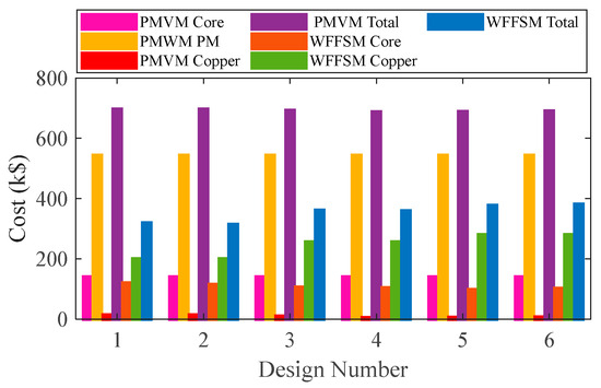
Figure 10.
Cost comparison for PMVM and WFFSM.
Table 5.
Mass and cost analysis of PMVM and WFFSM at Design Number 6.
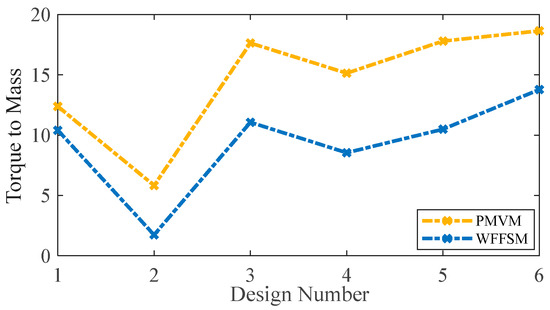
Figure 11.
Torque-to-mass comparison for PMVM and WFFSM.
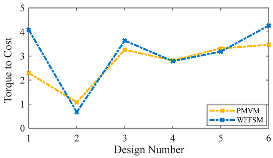
Figure 12.
Torque-to-cost comparison for PMVM and WFFSM.
4. Experimental Verification
To justify the Finite Element Analysis (FEA), a low-scale prototype of the WFFSM was developed in the authors’ previous studies [10,11], as shown in Figure 13, whereas the test platform along with the instruments used in the test rig is illustrated in Figure 14. From the test platform, it is observed that, to independently operate the inner and outer rotors to test the proposed WFFSM prototype for direct-drive counter-rotating wind turbine applications, the associated shafts are attached to two different prime movers on opposite sides of the prototype. The outer rotor is connected to the first prime mover, while the inner rotor is connected to the second prime mover. Both prime movers revolve in opposite directions and at the same speed during the counter-rotation test, with the first prime mover rotating counterclockwise and the second rotating clockwise. Additionally, because there is only one torque and speed sensor available, the inner port and inner rotor are tested first, and the outer rotor is subsequently fitted with a torque sensor for outer port and torque measurements. The experimental test is comprehensively analyzed with the effect of the rotational direction as well as uniform and non-uniform rotor poles.
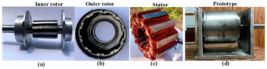
Figure 13.
Low-scale WFFSM: (a) inner rotor, (b) outer rotor, (c) stator, and (d) full prototype.
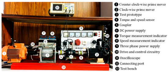
Figure 14.
Experimental test platform.
The first test is performed to study the effect of rotational direction with varying wound-field-excitation current density between 6 A/mm2 and 18 A/mm2 for the no-load back-EMF in co-rotation and counter-rotation in both inner and outer rotors, as shown in Figure 15 [11]. The inner rotor with co-rotation (IRCoR) and counter-rotation (IRCR) is illustrated in Figure 15a,b, whereas the outer rotor co-rotation (ORCoR) and counter-rotation (ORCR) are examined in Figure 15c,d. The experimental and finite element analysis (FEA) results for the no-load back-electromotive force (back-EMF) of the four topologies, i.e., IRCR, ORCoR, ORCR, and IRCoR, show a high degree of agreement between the measured and simulated waveforms, proving that the FEA models accurately predict the basic electromagnetic performance. The overall excellent correlation is not diminished by the small differences in the experimental data, which are likely due to manufacturing tolerances and unmodeled end effects. This validation provides high confidence in the application of the proposed models for subsequent design analysis and optimization for counter-rotating wind turbine applications.
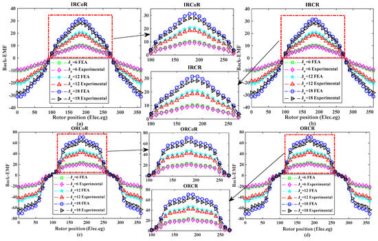
Figure 15.
Comparison of FEA and experimental results of no-load back-EMF in WFFSM: (a) IRCoR, (b) IRCR, (c) ORCoR, and (d) ORCR [11].
Furthermore, additional tests with uniform rotor poles () and non-uniform rotor poles and are conducted to study the torque profile and current-voltage characteristics curve (I–V curve), as shown in Figure 16 and Figure 17, respectively [10]. An experimental test is conducted to determine the average torque profile at different current densities while the machine is under load. To record the torque of the inner and outer rotors, this measurement test is also carried out in stages. Figure 16a displays the average torque profile for an inner rotor with uniform and non-uniform rotor poles, whereas Figure 16b displays the average torque profile for an outer rotor. The findings of the experiment and the FEA are found to be in reasonable agreement.
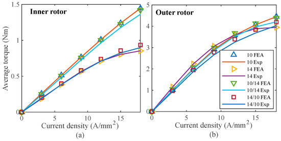
Figure 16.
Comparison of FEA and experimental results of average torque: (a) inner rotor, and (b) outer rotor [10].
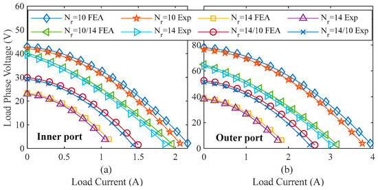
Figure 17.
Comparison of FEA and experimental results of output current and voltage curve in different operating states of variable resistive load: (a) inner port, and (b) outer port [10].
Finally, the I–V curve is tested under different operating states. The output current and voltage are examined with field excitation (If = 3A) under variable resistive load conditions, as shown in Figure 17, which matches the FEA results. It is noted that both FEA and experimental results align closely, with slight differences due to manufacturing tolerances and the effects of holes for nuts and bolts. It is worth noting that during the measurements, the discrepancy and percentage error between the measured and simulated results are found to be below 5%, which is within the acceptable range.
5. Conclusions
This study investigates the contra-rotating PMVM in comparison with the WFFSM to provide noteworthy insights into their electromagnetic performance at the MW power level. These insights are crucial for optimizing the design and selection of these machines for wind power applications, emphasizing the trade-offs between performance, efficiency, and cost in the pursuit of sustainable energy solutions. The PMVM exhibits superior torque and power with minimal cogging torque compared to the WFFSM. On the other hand, the WFFSM is more efficient and has an exceptional power factor compared to the PMVM. The efficiency and power factor of the PMVM are also noteworthy. Both machines can be considered promising candidates for large-scale, direct-drive, contra-rotating wind turbines and wind power applications. To validate the findings, the analysis has been authenticated by a low-scale experimental prototype.
Author Contributions
Conceptualization, M.F. and W.U.; methodology, W.U. and F.K.; software, M.F.; validation, W.U., U.B.A. and F.K.; formal analysis, M.F.; investigation, M.F. and W.U.; resources, F.K. and U.B.A.; data curation, M.F. and W.U.; writing—original draft preparation, M.F.; writing—review and editing, W.U., F.K. and U.B.A.; visualization, M.F.; supervision, F.K.; project administration, F.K. and W.U.; funding acquisition, W.U. and U.B.A. All authors have read and agreed to the published version of the manuscript.
Funding
This research was funded by Pakistan Science Foundation (PSF), grant number PSF/CRP/6/E/Indv-(234).
Institutional Review Board Statement
Not applicable.
Informed Consent Statement
Not applicable.
Data Availability Statement
Data will be available on request from corresponding author.
Conflicts of Interest
The authors declare no conflicts of interest.
Appendix A
| List of Symbols | |
|---|---|
| Symbols | Definition |
| Pole pair number | |
| Current per phase | |
| Magnetic flux linkage | |
| Phase number | |
| Angle between magnetic field and current | |
| Number of turns per phase | |
| Winding factor | |
| Flux per stator phase | |
| Rotor pole arc | |
| Leakage factor | |
| Stator pole pair number | |
| Outer diameter of the rotor | |
| Stack length | |
| Peak value of the inner air gap flux density | |
| Machine electrical loading | |
| Rotor pole number | |
| Stator slot number | |
| Gear ratio | |
| Flux | |
| d-axis inductance | |
| q-axis inductance | |
| d-axis current | |
| q-axis current | |
| Air-gap region | |
| Air-gap magnetic flux density | |
| Maximum air-gap flux density | |
References
- #WWEAwebinar: Wind Power Around the World (Recordings Available). 2021. Available online: https://wwindea.org/wweawebinar-wind-power-around-the-world (accessed on 9 November 2024).
- Simon, E.; Maureen, H.; Joachim, S.; Bentham, P. Analysis: Record-Low Price for U.K. Offshore Wind Cheaper Than Existing Gas Plants by 2023. 2019. Available online: https://www.carbonbrief.org/analysis-record-low-uk-offshore-wind-cheaper-than-existing-gas-plants-by-2023/ (accessed on 10 November 2024).
- Chen, H.; Zuo, Y.; Chau, K.T.; Zhao, W.; Lee, C.H.T. Modern electric machines and drives for wind power generation: A review of opportunities and challenges. IET Renew. Power Gener. 2021, 15, 1864–1887. [Google Scholar] [CrossRef]
- Padinharu, D.K.K.; Li, G.-J.; Zhu, Z.-Q.; Clark, R.; Thomas, A.; Azar, Z.; Duke, A. Permanent Magnet Vernier Machines for Direct-Drive Offshore Wind Power: Benefits and Challenges. IEEE Access 2022, 10, 20652–20668. [Google Scholar] [CrossRef]
- Fernando, N.; Nutkani, I.U.; Saha, S.; Niakinezhad, M. Flux switching machines: A review on design and applications. In Proceedings of the 2017 20th International Conference on Electrical Machines and Systems (ICEMS), Sydney, NSW, Australia, 11–14 August 2017; pp. 1–6. [Google Scholar]
- Kumar, P.S.; Abraham, A.; Bensingh, R.J.; Ilangovan, S. Computational and experimental analysis of a counter-rotating wind turbine system. J. Sci. Ind. Res. 2013, 72, 300–306. [Google Scholar]
- Li, Z.; Wang, Y.; Xiao, H. Experimental study on structures of counter-rotating wind turbines. In Proceedings of the 2013 International Conference on Materials for Renewable Energy and Environment, Chengdu, China, 19–21 August 2013; pp. 368–372. [Google Scholar]
- Li, Z.; Wang, Y.; Zhang, Y. Experimental study on interaction of the counter-rotating rotors in a wind turbine. In Proceedings of the 2011 International Conference on Materials for Renewable Energy & Environment, Shanghai, China, 20–22 May 2011; pp. 570–574. [Google Scholar]
- Bayron, P.; Kelso, R.; Chin, R. Experimental analysis of co-rotating and counter-rotating tandem horizontal-axis wind turbine performance and wake dynamics. J. Wind. Eng. Ind. Aerodyn. 2024, 253, 105840. [Google Scholar] [CrossRef]
- Ullah, W.; Khan, F.; Hussain, S.; Yousuf, M.; Akbar, S. A Novel Dual Port Dual Rotor Wound Field Flux Switching Generator with Uniform and Non-Uniform Rotor Poles for Counter-Rotating Wind Power Generation. IEEE Trans. Energy Convers. 2023, 38, 2420–2433. [Google Scholar] [CrossRef]
- Ullah, W.; Khan, F.; Akuru, U.B.; Hussain, S.; Yousuf, M.; Akbar, S. A Novel Dual Electrical and Dual Mechanical Wound Field Flux Switching Generator for Co-Rotating and Counter-Rotating Wind Turbine Applications. IEEE Trans. Ind. Appl. 2024, 60, 184–195. [Google Scholar] [CrossRef]
- Allahyari, A.; Torkaman, H. A Novel High-Performance Consequent Pole Dual Rotor Permanent Magnet Vernier Machine. IEEE Trans. Energy Convers. 2020, 35, 1238–1246. [Google Scholar] [CrossRef]
- Alavijeh, M.M.; Mirsalim, M. Design and optimization of a new dual-rotor Vernier machine for wind-turbine application. In Proceedings of the 2020 28th Iranian Conference on Electrical Engineering (ICEE), Tabriz, Iran, 4–6 August 2020; pp. 1–6. [Google Scholar]
- Fatima, M.; Khan, F.; Ullah, W.; Akuru, U.B. Mathematical sizing and design analysis of permanent magnet vernier machine for contra-rotating wind power applications. IET Electr. Power Appl. 2025, 19, e12531. [Google Scholar] [CrossRef]
- Liu, Y.; Zhu, Z.Q. Influence of gear ratio on electromagnetic performance and geometries of vernier permanent magnet synchronous machines. In Proceedings of the 2017 IEEE Energy Conversion Congress and Exposition (ECCE), Cincinnati, OH, USA, 1–5 October 2017; pp. 2453–2460. [Google Scholar]
- Allahyari, A.; Bostanci, E.; Mahmoudi, A. High-Performance Vernier Machines with Halbach Array Permanent Magnets for Direct Drive Applications. Machines 2023, 11, 525. [Google Scholar] [CrossRef]
- Padinharu, D.K.K.; Li, G.J.; Zhu, Z.Q.; Foster, M.P.; Stone, D.A.; Griffo, A.; Clark, R.; Thomas, A. Scaling Effect on Electromagnetic Performance of Surface-Mounted Permanent-Magnet Vernier Machine. IEEE Trans. Magn. 2020, 56, 8100715. [Google Scholar] [CrossRef]


Disclaimer/Publisher’s Note: The statements, opinions and data contained in all publications are solely those of the individual author(s) and contributor(s) and not of MDPI and/or the editor(s). MDPI and/or the editor(s) disclaim responsibility for any injury to people or property resulting from any ideas, methods, instructions or products referred to in the content. |
© 2025 by the authors. Licensee MDPI, Basel, Switzerland. This article is an open access article distributed under the terms and conditions of the Creative Commons Attribution (CC BY) license (https://creativecommons.org/licenses/by/4.0/).