Abstract
The construction sector is a significant contributor to resource consumption and environmental degradation due to energy-intensive processes. To reduce consumption, reuse-based design strategies could lead to structurally efficient and environmentally friendly solutions. However, effectively incorporating reused elements requires advanced design methods that allow for their rational disposition. This paper presents an innovative design approach based on a metaheuristic strategy developed through genetic algorithms for the design of minimum-weight gridshells using reusable components. The methodology is applied to a dome gridshell, tested under different stock and boundary conditions. An expedited greenhouse gas assessment is then carried out to evaluate the environmental benefits of the reuse-based solutions compared to solutions composed entirely of new elements. The results are presented in terms of geometry, disposition of reused and new members, weight, structural performance (buckling factor, demand to capacity ratio, displacements), and greenhouse gas emissions. The algorithm is able to find the minimum weight solution for all the considered stocks, and to account for the different governing design criteria characterizing fully and partially constrained gridshells. Furthermore, it can also be used to determine the characteristics that the stock of reused elements should possess in order to achieve more sustainable design solutions.
1. Introduction
Steel gridshells are a class of lightweight structures largely used for their ability to cover large spans with minimal material through their double-curvature shapes. Indeed, these structures adopt the shape and exploit the global behavior of thin shells, but they are built as grids. Their reduced material usage makes them structurally and environmentally efficient; however, their geometrical slenderness, the frequent presence of geometric imperfections, or the presence of semi-rigid connections, also makes them particularly sensitive to global buckling phenomena. This requires accurate design approaches capable of ensuring both strength and stability requirements [1]. Nevertheless, their nature as lightweight steel structures makes them particularly suitable for pursuing the goal of realizing sustainable structures, especially if recycled steel is used, or, even better, if they are made with reused structural elements. In this framework, while recycling is energy-intensive for material recovery and processing [2], the concept of reuse offers the potential to greatly reduce environmental impact by introducing structural elements derived directly from demolished buildings into new structures [2,3,4]. Furthermore, the long-term durability of steel components makes them particularly suitable for reuse, as highlighted by life cycle assessment analyses performed by Rossi [5] that underline their high level of recoverability at the end of life of buildings comprising them. This aspect is also highlighted by the work of Umaraj et al. [6], which draws inspiration from the aerospace industry’s success with reusable rockets to ask: “If Rockets are Reusable Why Not Buildings?”. They investigated, both numerically and experimentally, the potential for reusing cold-formed, unequal-leg lipped steel angles, which are common structural components in steel-framed buildings, with the result that these components can satisfy design standards similar to those of new elements.
Despite the potential of reused-steel structural components, the literature presents few examples of reuse-oriented approaches focused on conventional structural systems [2,3,4,7,8,9]. The innovative aspect of the paper is not only the proposed strategy for incorporating reused members into the design of new gridshells, but also the introduction of optimization approaches to determine the best arrangement of reused members in order to obtain lightweight solutions. To the authors’ knowledge, this topic represents a gap in the current literature, owing to its novelty within the broader context of the community’s increasing sensitivity toward sustainable solutions.
The inclusion of reused components, which are characterized by defined properties in terms of strength, cross-section shape and dimensions, and lengths, requires the definition of ad hoc design approaches to strategically allocate the reused members. To this end, a design framework based on optimization is particularly well-suited. In this field, several literature works deal with innovative design approaches based on the combinations of sizing, topology, and shape optimization techniques [10,11,12,13,14,15], but only a few contributions are present for the design of gridshells with reused components [9,16,17].
The aim of this paper is to propose a design strategy for the minimum weight design of gridshells with reused components. In particular, the proposed approach strategically merges a geometry and a sizing optimization approach with the aim of incorporating the maximum possible number of reused members selected from a stock of reusable beams, while minimizing weight and satisfying constraint conditions on buckling factor, stresses, and stiffness. The joint positions constitute the variables of the optimization problem and are modified by a genetic algorithm to reduce the value of the objective function. The latter includes the weight of the new members to be minimized, as well as penalty functions accounting for constraint conditions imposed on the buckling factor, the maximum utilization value (i.e., the demand-to-capacity ratio), and the maximum displacement. For each analyzed joint configuration, a subroutine matches each element with a reusable beam of similar length and introduces these elements into the gridshell, assigning them the cross-section provided by the stock. The cross-section of the new beams is treated as an additional variable of the optimization process. In order to test the proposed approach on gridshells with varying structural requirements that cover real-world cases, it has been applied to both fully constrained gridshells and partially constrained gridshells, the latter being scarcely studied in the literature [18]. In particular, the dome gridshell proposed by the Freegrid Benchmark [19] has been taken into account. This dome has been designed considering different stocks of reusable members, characterized by different numbers of elements, lengths, and cross-sections; this allows for the analysis of the effects of the characteristics of the reused stocks on the final solution. Furthermore, the obtained gridshells are discussed through the results in terms of greenhouse gas emissions, successively named GHG emissions [3], evaluated with a simplified formulation that supports early-stage design decisions. This work is developed in continuity with previous works [8], but introduces a more refined process and applies it to a broader range of case studies, including partially constrained dome-gridshell configurations, thereby demonstrating its high level of generalization and robustness.
2. Materials and Methods
The proposed optimization approach merges geometry and sizing optimization for the minimum-weight design of gridshells composed of a mix of new and reused components. At a high level, the method aims to identify the optimal configuration in terms of structural weight by simultaneously varying the joint coordinates of the gridshell and the cross-sections of new elements, while maximizing the incorporation of reused components. The algorithm begins with the generation of a parametric geometrical model, where the connectivity between lines is fixed, but the positions of the joints are treated as variables within the optimization problem. For each analyzed configuration of joint positions, a subroutine compares the lengths of the lines to the available lengths of reusable components provided by an external stock of structural elements (beams). The joint positions are then slightly adjusted to maximize the number of lines whose lengths match those available in the stock. After this adjustment, a structural model is created by assigning structural elements to the lines. Specifically, for lines whose lengths match those in the stock, the corresponding cross-sections from the stock are assigned (hereafter referred to as “reused beams”), while for the remaining elements (hereafter referred to as “new beams”), the cross-sections are treated as variables in the optimization problem. Furthermore, material properties, loads, and support conditions are assigned to the structural model. Subsequently, structural analyses are conducted, including linear static and linear buckling analyses, to evaluate the weight of the new beams, the buckling factor, the utilization factor (i.e., demand-to-capacity ratio), and the maximum displacement. These parameters are incorporated into the calculation of the objective function. Since the goal is to minimize the weight of the new beams, the objective function is defined as the sum of this and a series of penalty functions. These penalties account for the buckling factor, utilization factor, and maximum displacement, thereby ensuring that the generated solutions meet stiffness and strength requirements. If an optimal solution is reached, the algorithm terminates and returns the corresponding configuration. Otherwise, the current value of the objective function is used as input for a genetic algorithm, which iteratively searches for improved solutions by simultaneously varying the joint positions and the cross-sections of the new beams.
The entire process is detailed in Section 3, with specific focus on the parametric geometrical model, the structural model and analysis, and the optimization procedure. All the steps of the workflow have been implemented using Grasshopper (version 1.0.0008) [20] (parametric model and optimization algorithm), a Rhino (version 8) plug-in [21], and Karamba3D (version 3.1.50925.0) [22] (structural analyses).
The full workflow has been implemented in a parametric environment: Grasshopper [20] (Rhino [21] plug-in) for geometry generation and genetic algorithm optimization; Karamba3D for linear static and linear buckling analyses [22]. This integration enables a fully automated framework where geometry, stock compatibility, structural verification, and optimization are continuously coupled. As a result, the proposed process can handle diverse gridshell configurations and boundary conditions, while embedding reuse-based strategies at the very core of the design.
In summary, the optimization problem is driven by a dual goal:
- reduce the mass of newly manufactured members (Wnew);
- maximize the incorporation of elements selected from a predefined stock of reclaimed beams.
These objectives are subjected to structural design requirements:
- Global stability, expressed through a minimum buckling factor (BF ≥ 1);
- Local strength, controlled by the maximum utilization ratio (Umax ≤ 1), where the utilization ratio is a demand to capacity ratio;
- Serviceability, verified through the displacement ratio (Δ ≤ 1), defined as the ratio between maximum Dmax and the limit displacement Dlim (set equal to B/250, with B being the dome span).
The optimization problem can be expressed as:
where the joints movements are constrained to move in a range amin–amax with respect to the two orthogonal directions of the base plane (x-y) of the gridshell, while their height in the z direction is constrained to belong to the predefined surface. In this formulation, the design task is not only a search for a lightweight solution, but also an exploration of how reclaimed members can be strategically allocated to satisfy stringent stability and strength conditions.
The entire process has been structured in a multi-level design process, mainly defined by four levels, that will be detailed in Section 3, dealing with the generation of the geometric configuration, the integration of reclaimed members, the development of structural analyses and output readings, and the optimization phase, respectively.
3. Multi-Level Design Process
The multi-level design process is described in the following sub-sections, with specific reference to the flowchart represented in Figure 1.
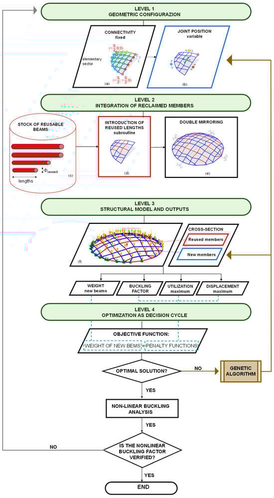
Figure 1.
Flow chart of the proposed multi-level process: (a) definition of the connectivity between elements (green: internal joints; cyan: joints positioned on the external boundary; yellow: joints positioned on the internal boundary parallel to the x-axis; brown: joints positioned on the internal boundary parallel to the y-axis; pink: joints positioned at the corners); (b) definition of the joint variables; (c) stock of reusable beams; (d) introduction of reused elements in function of their lengths (red: reused beams; blue: new beams); (e) entire geometry and disposition of reused and ne beams; (f) structural model.
3.1. Level 1—Geometric Configuration
The first operational step of the framework is the generation of a parametric gridshell geometry. The connectivity of the grid is fixed, but the positions of joints are treated as design variables. The geometry is created starting from an elementary sector of the dome, which is subsequently mirrored to preserve double symmetry (Figure 1). The generation process begins with an elementary sector (Figure 1a), which is mirrored four times to complete the full geometry (Figure 1e). The geometries of the elementary sector are generated by varying the positions of the joints along a surface, starting from an initial regular gridshell made of a square mesh (Figure 1a). The geometric parameters of the algorithm correspond to the movements of the joints used to modify the grid (Figure 1a). Given the double symmetry of the gridshell and the curvilinear shape of the dome’s boundary, displacement constraints are applied to the boundary and corner joints to preserve both the overall symmetry and the dome’s footprint:
- Joints positioned on the internal boundary parallel to the x-axis (yellow in Figure 1a,b) can move exclusively in the x-direction, while the z is evaluated in order to belong to the generatrix, considering xI,j the initial x-coordinate of the j-th joint, xF,j its final x-coordinate, and zF,j the final z-coordinate:where B is the generatrix span, and f = B/8 is the rise in the generatrix span.
- Joints positioned on internal boundary parallel to the y-axis (brown in Figure 1a,b) are allowed to move exclusively in the y-direction, while the z is evaluated in order to belong to the generatrix, considering yI,j the initial y-coordinate of the j-th joint, yF,j its final y-coordinate, and zF,j the final z-coordinate:
- Joints positioned at the corners (pink in Figure 1a,b) are fixed and not permitted to move:
- Joints positioned on the external boundary (cyan in Figure 1a,b) are allowed to move only along the perimeter curve, thereby preserving the original footprint; considering that the perimeter is a circumference, while the new x-coordinate is a variable, the new y-coordinate is evaluated in order to belong to the circumference, and the z-coordinate is zero:
- Internal joints (green in Figure 1a,b) are allowed to move freely in both x and y directions.
The maximum allowable displacements in the x and/or y directions are limited within predefined bounds to prevent overlap between adjacent joints. These movement constraints are defined to ensure geometric compatibility with the available reusable elements and to maintain the structural coherence, symmetry, and architectural intent of the dome configuration. A preliminary configuration of the elementary sector of the gridshell is first defined (Figure 1b).
3.2. Level 2—Integration of Reclaimed Members
Once the geometry is generated, the algorithm evaluates the compatibility between the structural lines of the grid and the available stock of reclaimed members. A dedicated subroutine is then implemented to identify the lines within the modified grid whose lengths are close to those of the elements available in the stock of reusable beams, as highlighted in green in Figure 1c. Subsequently, the corresponding end joints are adjusted to match the lengths of the selected reusable elements (Figure 1d), following a predefined set of rules:
- The starting joints of the selected lines are moved in order to shorten or lengthen the lines to reach the target length of the reusable beams.More in detail, considering the j-th line of the elementary sector of the gridshell, defined by the starting joint PS,j, and the end joint PE,j, with initial coordinates:The original length of the line is computed as:Considering a reusable beam with a length LR, the objective is to modify the starting joint (here, PS,j) such that the new element length is exactly equal to LR.To this aim, the movements of the original element are:The modified coordinates (xs,j′, ys,j′, zs,j′) of the new starting Ps,j′ are given by:
- If the starting joint of a selected line coincides with the starting joint of another line also selected for adjustment, the ending joint is moved instead. The formulation is the same as previously described, but refers to the end joint.
- If the joint to be moved lies along one of the symmetry axes, it is allowed to move only along the x- or y-direction, and additionally along the z-direction to achieve the desired line length. The formulation is the same as previously described, but restricted to movements along the x- or the y-direction.
- If the joint lies on the external boundary of the sector, it is allowed to move only along the perimeter curve to match the required length. However, movement along the z-direction is not permitted for these joints, as they are externally constrained in the structural model. In this case, the coordinates of the updated point PF,j′ is defined in a function of an angle θ and the radius of the arc r of the circumference that defines the perimeter:By imposing the distance between the points PF,j′ and PS,j equal to the length LR, θ is equal to:
3.3. Level 3—Structural Model and Outputs
After the definition of the geometric configuration and the integration of reclaimed members, the structural model of the resulting gridshell configuration must be defined. In particular, the cross-section and material properties derived from the stock are assigned to the reused beams. In contrast, the cross-section of the new beams is treated as a variable in the optimization problem. For example, in the present study, if the cross-sections are assumed to be circular hollow sections (pipes), the diameter of the new pipes (ϕnew) is considered an optimization variable, while the wall thickness (tnew) is defined as a function of ϕnew. On the other hand, the diameters (ϕreused) and thicknesses (treused) of the reused beams are selected from the available stock. All structural members are modeled as beams, assuming fixed connections at all joints. The loads are applied as forces acting to the joints. Support conditions depend on the case under analysis, which can be a fully constrained gridshell (with hinged supports at the base) or a free-edge gridshell (with partially constrained supports at the base). The structural model, during the design phase, is analyzed through linear static and linear buckling analyses. These analyses provide the information to evaluate the objective function, which is evaluated considering the structural weight of the new members (Wnew) and the performance metrics, such as the global linear buckling factor (BF), the maximum displacement ratio (Δ), and the maximum utilization ratio (Umax). Specifically:
- the linear buckling factor (BF) should be greater than 1 to ensure safety against global buckling phenomena;
- the maximum displacement ratio (Δ), defined as the ratio between the maximum displacement (Dmax) and the allowable displacement limit (Dlim = B/250), have to be less than 1;
- Umax is the maximum utilization ratio among all members, defined as the demand-to-capacity ratio [23].
3.4. Level 4—Optimization as Decision Cycle
The optimization engine is a mono-objective genetic algorithm. It simultaneously perturbs joint positions and cross-sections of new beams, while assigning reclaimed members where available. The objective function is defined as:
where cj are penalty functions associated with constraint violations (BF, Umax, Δ), and αj are penalty factors that ensures that infeasible solutions are discarded. In particular, the penalty functions cj are defined as:
where α1, α2, and α3 have been imposed equal to 103 in order to be one order of magnitude larger than the weight (in kN) of the reference solutions designed with all new beams through a simple sizing optimization approach (base cases).
The whole process continues iteratively:
- Candidate geometries are generated.
- Structural analyses are performed.
- Penalties are applied when constraints are not met.
- The genetic algorithm evolves the population until convergence.
In particular, concerning point 4, the genetic algorithm employed is Galapagos [24]. The algorithms start from the generation of the first population with random individuals, whose number is set in the algorithm by the parameters Population (50) Initial Boost (2). Then, Galapagos evaluated the OF of each individual of the current population, and selects the ones to be parents in order to generate the individuals of the next generation, whose number is defined by the parameter Population. Galapagos creates successive generations by survival (percentage of best individuals, set by the parameter Maintain set equal to 5%), by coupling (based on the genetic distance and governed by the parameter Inbreeding Factor set equal to 75%), and by random genetic variations in the parents (controlled by the parameter Mutation). The process stops when no variations in terms of OF is made for a specified number of generations (Max Stagnant, set equal to 50).
4. Case Study and Numerical Applications
The proposed design optimization process has been applied to a gridshell case proposed within the Freegrid benchmark [19], and graphically shown in Figure 2a. In particular, the dome configuration was selected, which is formed by a parabolic generatrix (in blue) and a parabolic directrix (in red) with Equations:
where
where B = 30 m is the generatrix span; f = B/8 is the rise in the generatrix span.
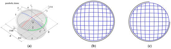
Figure 2.
Plan and axonometric view of the accounted case: (a) 20 × 20 dome proposed by [19]; 10 × 10 dome gridshell designed by Authors: (b) fully constrained gridshell. Reprinted from Ref. [9], (c) free-edge gridshell.
The selected gridshell is subjected to a vertical uniform distributed load of 1800 N/mm2 at the Ultimate Limit State (ULS), and of 1200 N/mm2 at the Service Limit State (SLS), applied as concentrated forces to the joint of the grid, in order to replicate the Load Condition LC1 described in [19]. The analyses at the ULS are used to verify the solutions in terms of strength (Umax) and buckling factor (BF), while the analyses at the SLS are used to verify the deformability (Δ). About the support conditions, two cases are considered:
The mesh discretization was assumed to be of 10 × 10 square elements (Figure 2b,c), instead of the 20 × 20 (Figure 2a) elements considered in [19], in order to reduce computational time. Pipe cross-sections made of steel class S355 with a diameter-to-thickness ratio of 10 were assigned to all beams. Steel of class S355 is considered as the material for both reused and new members, and in the design phase, the material is assumed to behave as linear elastic (since the optimization refers to linear static and linear buckling analyses), adopting the corresponding Young’s Modulus and yielding stress. With regard to the reused members, the material is assumed to have the same properties as the new one, under the hypothesis that appropriate tests have been carried out to confirm the mechanical characteristics of the reused material, as required by the relevant guidelines [25]. Furthermore, in this work, according to the relevant guidelines [25], the reused steel members have been assumed not to have significant imperfections or permanent deformations, to be free from material loss due to corrosion beyond surface effects, and not to have been subjected to impact, fatigue from repeated loading, or fire.
The proposed optimization process has been applied to the dome gridshell by considering different stock scenarios of reusable beams defined by varying the number (N) and the length (L) of the reused elements to be inserted in the elementary sector of the gridshell (also, the position of reused beams is double-mirrored in order to define the entire gridshell). In detail, five stock scenarios are considered:
- stock (a): N = 8—L = 4 m;
- stock (b): N = 12—L = 4 m;
- stock (c): N = 8—L = 5 m;
- stock (d): N = 12—L = 5 m;
- stock (e): N = 12—L = 4 m (4 elements); L = 4.5 m (4 elements); L = 5 m (4 elements).
Considering the proposed stocks, a first set of analyses was performed by assuming that the elements of the stocks are characterized by the same cross-section shape (pipe) and dimensions (CS1): diameter ϕreused = 101 mm; thickness treused = ϕreused/10. A second set of analyses (CS2) was performed by assuming a diameter and a thickness of reused members twice that of CS1, i.e., a diameter ϕreused = 202 mm, thickness treused = ϕreused/10.
5. Results
The results in terms of geometry and positioning of new and reused beams are shown in Figure 3 and Figure 4 for the cases of the fully constrained gridshell and free-edge gridshell, respectively. For both cases, pictures on the left refer to the solutions with the smaller cross-section assigned to reused members (CS1), whilst pictures on the right refers to the solutions with the larger cross-section assigned to reused beams (CS2). To simplify the reading, each solution is labeled by L = l_N = n_CSi, where l is the length of the beams of the stock, n is the number of reusable beams, and i is equal to 1 for CS1 or equal to 2 for identifying CS2. Considering fully constrained gridshells, the geometry and the disposition of reused beams seem quite similar for the two different considered cross-section dimensions of reused beams. On the other hand, notable differences can be observed in terms of geometry considering different stocks in terms of number and length of beams. Differently, by observing the configuration of free-edge gridshells, it varies more clearly between the two different cross-sections of reused beams considered. Analogous to the fully constrained gridshells, notable differences can also be observed in this case, in terms of geometry, considering the differing stocks in terms of their number and length of beams.
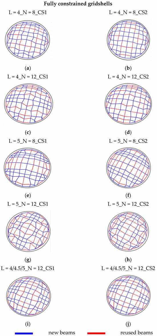
Figure 3.
Fully constrained gridshells: topology and disposition of new and reused beams. Reprinted from Ref. [9].
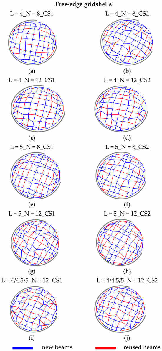
Figure 4.
Free-edge gridshells: topology and disposition of new and reused beams.
Figure 5 shows that all the solutions obtained for the stocks with the smaller cross-section CS1 provide smaller total weights than the reference case, with a percentage of reused beams in the range 18–34%. The reduction in terms of total weight, instead, varies between 6% (L = 4_N = 12_CS1) and 19% (L = 5_N = 8_CS1); this range of variation testifies the effect of the lengths of the reusable beams on the design process. In this particular case, the elements with a length of 5 m fit better than those of 4 m. Furthermore, for all the cases, an increase in the number of reused beams leads to an increase in total weight, since a more stringent condition is applied to the design problem. Conversely, the solutions obtained for the stocks with a larger cross-section CS2 are characterized by higher weights with respect to the base case, with an increase in the range 12–56%; further, a high percentage of Wreused with respect to the total weight is presented in the range 57–77%. Nevertheless, the solutions from CS2 are characterized by a high percentage of reused beams, and, in terms of total weight, are not preferable with respect to the solutions from CS1. This result clearly shows that the effectiveness of the design in terms of structural weight is closely connected to the characteristics of the available stock, i.e., the length of the elements, but even more to their cross-sectional dimensions. By analyzing the results, it is possible to observe that one of the constraints influencing the obtained solutions is the buckling factor (BF), which results in slightly higher values than the limit value of 1. Additionally, for some cases, the maximum values of utilization Umax are close to the limit value of 1, suggesting that these solutions are optimized for both strength and stability requirements. However, in general, the design of the proposed fully constrained gridshells is governed by their susceptibility to buckling phenomena. The displacement ratio Δ results in values generally smaller than the limit value of 1, confirming the high rigidity of the gridshells conferred by their double curvature. Regarding free-edge gridshells, Figure 6 shows that the solutions in terms of total weight do not follow the same pattern in terms of the reduction/increase in total weight compared to the base case. In fact, almost all the solutions show a reduced total weight with the exception of two cases: one characterized by the lower cross-sections of reusable beams CS1 (L = 4_N = 8) and another characterized by the higher cross-sections of reusable beams CS2 (L = 5_N = 8), with an increase of about 4.7% and 7.3%, respectively. Considering the above, the solutions from CS1 and CS2 are characterized by a reduction in terms of total weight with respect to the base case, ranging from 16.5% to 35.3% and from 5.2% to 24.74%, respectively. On the other hand, the solutions from CS1 have a small percentage of reused beams, ranging from 5% to 12%, while in the solutions from CS2, the percentage of these is considerably higher (21–42%).
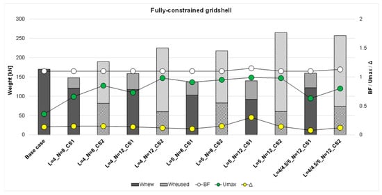
Figure 5.
Fully constrained gridshells: results in terms of Wnew and Wreused (weight of new and reused beams, respectively), BF (buckling factor), Umax (maximum utilization), Δ (displacement ratio). Solid: solutions from CS1; Striped: solutions from CS2. Reprinted from Ref. [9].
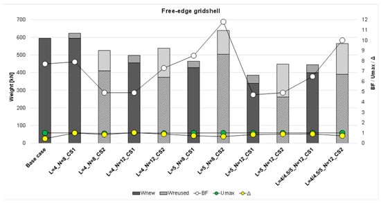
Figure 6.
Free-edge gridshells: results in terms of Wnew and Wreused (weight of new and reused beams, respectively), BF (buckling factor), Umax (maximum utilization), Δ (displacement ratio). Solid: solutions from CS1; Striped: solutions from CS2.
Considering the utilization ratios (Umax) for all cases, these values are consistently slightly below the limit value of 1, and also the maximum displacement ratio (Δ) reaches values slightly below the limit value of 1, suggesting that these solutions are optimized to simultaneously meet both strength and stiffness requirements. In the free-edge gridshells, the buckling factors are always greater than 1, ranging from approximately 5 to 12. These results indicate a difference in structural behavior between the fully constrained and free-edge gridshells. In the former, the design is primarily governed by buckling phenomena, meaning that failure is due to a global loss of stability affecting the entire structure. In contrast, in the free-edge gridshells, the design is governed by both material strength and deformability. Despite these differences in structural behavior, the proposed design approach successfully addresses the varying requirements for stiffness, strength, and stability across both types of case studies, namely, the fully constrained and the free-edge gridshells.
By observing the geometries obtained for both the fully constrained and the free-edge gridshells (Figure 3 and Figure 4, respectively), and comparing them with the structural performance results (Figure 5 and Figure 6), it becomes evident that the central region of the domes consistently contains longer members. In the case of the fully constrained gridshell, the design is governed by buckling. From the trend of the first buckling mode (qualitatively indicated by the dotted sphere in Figure 7a), it is clear that the central part is not significantly involved in the instability phenomena; therefore, a lower mesh density is adequate in this region. Conversely, the design of the free-edge gridshell is controlled by deformability and strength requirements. From the nodal displacement distribution (qualitatively shown by the dotted sphere in Figure 7b), it is evident that the free edge is particularly deformable, and thus a higher mesh density is required in the external part of the dome.
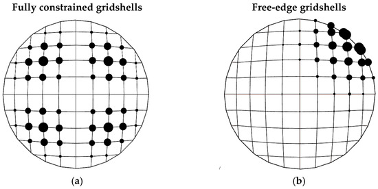
Figure 7.
(a) I Buckling Mode; (b) Displacements.
6. Discussion
To complement the results obtained through the optimization process here proposed and better understand the implications of reuse-based design strategies, the obtained solutions are also evaluated in terms of environmental advantage, through the estimations of GHG emissions. These supplementary investigations allow for a deeper understanding of the structural admissibility and environmental benefits of the optimized solutions.
One of the advantages of using reused members is certainly to reduce the weight and the number of new components, and hence the cost. Aside from this, another fundamental aspect for evaluating solutions, including reused components, is the potential reduction in the environmental impact. However, the quantification of the environmental impact is quite complex, as it involves multiple factors that are often difficult to evaluate. In this context, the studies available in the current literature [2,26] suggest the evaluation of the CO2 emissions produced during the construction process, including the dismantling of decommissioned structures, transportation of reusable members, realization of new components, and assembly of the members. The emissions are typically measured in terms of Greenhouse Gas Emissions (GHG). In this context, Brütting et al. [2] proposed a simplified formula based on reference values for CO2 emissions provided in [26], and data derived from [27] and the Swiss federal LCA database [28], which depends on the mass of reused members, the mass of new members, in addition to the amount of waste, which is not included in this work:
where Mreused and Mnew are the masses of reused and new members in kilograms, respectively.
Figure 8 and Figure 9 present the plotted results deduced from Equation (21) for both the fully constrained gridshells and the free-edge gridshells, respectively. The figures also include the case composed of new members only (base case). The results referring to the fully constrained gridshell (Figure 8) show that GHG emissions similar to those from the base case, are associated with two cases characterized by the cross-section CS2 for reused beams, i.e., L = 5_N = 12 and L = 4/4.5/5_N = 12, whereas the other solutions show lower values. A similar line of reasoning can be applied to free-edge gridshells (Figure 9), where two cases characterized by the cross-section CS2 for reused beams, i.e., L = 5_N = 8 and L = 4/4.5/5_N = 12, provide almost the same values of GHG emissions as the base case, and one case, namely, L = 4_N = 8_CS1, shows a slightly higher value. The other seven solutions provide GHG emission values lower than those of the base case. This result further emphasizes how fundamental stock selection is for achieving improved outcomes, also in terms of environmental impact. It highlights that incorporating reused elements does not automatically ensure a lower environmental footprint compared to using entirely new components. Following this line of reasoning, the proposed method can also be applied to theoretical element stocks, with the aim of identifying the necessary characteristics, in terms of cross-sectional dimensions and lengths, that a real stock should possess in order to obtain solutions optimized for both structural and environmental performances.
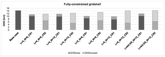
Figure 8.
Fully constrained gridshells: results in terms of greenhouse gas emissions (GHG). Solid: solutions from CS1; Striped: solutions from CS2.
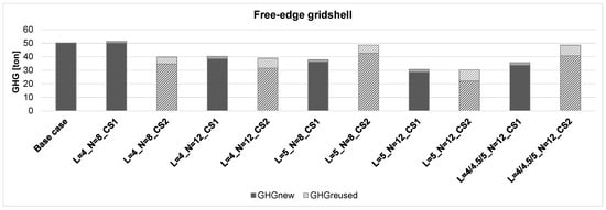
Figure 9.
Free-edge gridshells: results in terms of greenhouse gas emissions (GHG). Solid: solutions from CS1; Striped: solutions from CS2.
Downstream of all the obtained results, the main advantage of the proposed method is the ability to include reused members in the design solution of new gridshells, which clearly reduces the cost due to the significant reduction in the amount of new material required. The drawback is that the solutions obtained do not always perform better in terms of GHG emissions; however, in order to favor solutions with lower GHG emissions compared to those composed entirely of new members (base case), it is possible to adopt GHG emissions as the objective function and allow the algorithm to discard reused elements whenever their use would result in higher GHG emissions than the gridshell designed entirely with new members.
7. Conclusions
This study introduces an optimization design process that strategically combines geometric and sizing optimization for steel gridshells designed with reused structural elements. The integration of parametric modeling, rule-based geometry generation, and genetic algorithms creates a fully automated framework for generating, evaluating, and selecting structurally efficient and environmentally friendly designs. The proposed methodology has been applied to a case study from the existing literature, i.e., a dome gridshell, considering several scenarios defined by stocks of reclaimed elements with varying characteristics. Furthermore, the approach was applied to both a fully constrained gridshell at the base, and to a partially constrained one, in order to show the applicability of the approach under different conditions and to cover real-word example of gridshells. The main outcomes of the work could be discussed in terms of weight efficiency, governing design criteria, and environmental performance:
- Weight efficiency: for fully constrained gridshells, the use of reclaimed members with smaller cross-sections (CS1) led to a total weight reduction between 6% and 19% compared to the base case (i.e., the regular gridshell designed with a simple sizing optimization approach considering all new members), with 18–34% of members reused. Conversely, when using larger reused cross-sections (CS2), the final solutions showed 12–56% higher total weight, despite 57–77% reused material, highlighting the strong influence of stock geometry on structural efficiency. In free-edge gridshells, most scenarios achieved weight reductions between 16.5% and 35.3% (CS1) and between 5.2% and 24.7% (CS2), with reused material ranging from 5–12% (CS1) to 21–42% (CS2).
- Governing design criteria: the optimization results show that fully constrained gridshells are predominantly governed by global buckling, with optimal configurations achieving BF values slightly above 1 while respecting capacity (Umax = 1) and stiffness limits (Δ < 1). Free-edge gridshells, instead, are governed by strength and deformability, with BF ranging from 5 to 12, confirming stronger resistance to global instability but increased sensitivity to serviceability constraints.
- Environmental performance: the evaluation of greenhouse gas emissions (GHG) revealed that not all reuse-based solutions automatically provide more sustainable outcomes. For fully constrained gridshells, most CS1 scenarios achieved lower GHG emissions, while two CS2 cases resulted in emissions comparable to the baseline. For free-edge gridshells, seven out of ten reuse-based solutions produced lower GHG values, whereas two CS2 cases performed similarly to the baseline and one CS1 case showed a slight increase.
These findings demonstrate that the characteristics of the available stock are decisive parameters for ensuring both structural and environmental efficiency.
Overall, the proposed approach successfully integrates reused components into the design of new gridshells, identifying optimized configurations that satisfy strength, stiffness, and stability requirements while reducing the need for newly manufactured members. The results also highlight that reuse becomes environmentally advantageous only when stock characteristics are compatible with the structural demands of the system. The methodology can therefore also be used as a decision-support tool for determining the optimal properties that reclaimed element stocks should possess.
Author Contributions
Conceptualization, V.T., M.S., E.G. and M.I.; methodology, V.T., M.S., E.G. and M.I.; software, V.T. and M.S.; validation, V.T., M.S., E.G. and M.I.; formal analysis, V.T. and M.S.; investigation, V.T., M.S., E.G. and M.I.; resources, M.I.; data curation, V.T. and M.S.; writing—original draft preparation, V.T. and E.G.; writing—review and editing, V.T., E.G. and M.I.; visualization, V.T. and M.S.; supervision, E.G. and M.I.; project administration, M.I.; funding acquisition, M.I. All authors have read and agreed to the published version of the manuscript.
Funding
The research leading to these results has received funding from the Project “Re_Grid—Reuse-based optimization approach for environmentally efficient steel Grid structures” CUP H53D23008610001 funded by EU in NextGenerationEU plan through the Italian “Bando Prin 2022—D.D. 1409 del 14-09-2022” by MUR.
Data Availability Statement
The original contributions presented in this study are included in the article. Further inquiries can be directed to the corresponding author.
Acknowledgments
During the preparation of this manuscript, the authors used ChatGPT-5 for superficial text editing. The authors have reviewed and edited the output and take full responsibility for the content of this publication.
Conflicts of Interest
The authors declare no conflicts of interest.
References
- Kato, S. Guide to Buckling Load Evaluation of Metal Reticulated Roof Structures 2014; Report of Activities of IASS WG 8; IASS (International Association for Shell and Spatial Structures): Madrid, Spain, 2014. [Google Scholar]
- Brütting, J.; Senatore, G.; Schevenels, M.; Fivet, C. Optimum Design of Frame Structures From a Stock of Reclaimed Elements. Front. Built Environ. 2020, 6, 57. [Google Scholar] [CrossRef]
- Brütting, J.; Senatore, G.; Fivet, C. Design and fabrication of a reusable kit of parts for diverse structures. Autom. Constr. 2021, 125, 103614. [Google Scholar] [CrossRef]
- Brütting, J.; Desruelle, J.; Senatore, G.; Fivet, C. Design of Truss Structures Through Reuse. Structures 2019, 18, 128–137. [Google Scholar] [CrossRef]
- Rossi, B. Discussion on the use of stainless steel in constructions in view of sustainability. Thin-Walled Struct. 2014, 83, 182–189. [Google Scholar] [CrossRef]
- Umaraj, R.R.; Selvaraj, S.K.; Chan, T.-M.; Elghazouli, A.Y. If Rockets are Reusable Why Not Buildings? Reuse Evaluation for Cold-Formed Steel Unequal-Leg Lipped Angle Columns. Thin-Walled Struct. 2025, 216, 113463. [Google Scholar] [CrossRef]
- Van Marcke, A.; Laghi, V.; Carstensen, J.V. Automated planar truss design with reclaimed partially disassembled steel truss components. J. Build. Eng. 2024, 84, 108458. [Google Scholar] [CrossRef]
- Tomei, V.; Grande, E.; Imbimbo, M. A novel optimization approach for the design of environmentally efficient gridshells with reclaimed steel members. Adv. Eng. Softw. 2025, 200, 103825. [Google Scholar] [CrossRef]
- Tomei, V.; Serpe, M.; Grande, E.; Imbimbo, M. Designing Gridshells Using Reused Members as a Sustainable Solution. Buildings 2025, 15, 2198. [Google Scholar] [CrossRef]
- Tomei, V. The effect of joint stiffness on optimization design strategies for gridshells: The role of rigid, semi-rigid and hinged joints. Structures 2023, 48, 147–158. [Google Scholar] [CrossRef]
- Liu, J.; Xia, Y. A hybrid intelligent genetic algorithm for truss optimization based on deep neutral network. Swarm Evol. Comput. 2022, 73, 101120. [Google Scholar] [CrossRef]
- Favilli, A.; Laccone, F.; Cignoni, P.; Malomo, L.; Giorgi, D. Geometric deep learning for statics-aware grid shells. Comput. Struct. 2024, 292, 107238. [Google Scholar] [CrossRef]
- Ding, C.; Zhao, Y.; Ye, J.; Wang, Z.; Tang, H.; Xie, Y.M. An efficient and robust shape optimization framework for gridshell designs based on node shifting method. Structures 2024, 62, 106209. [Google Scholar] [CrossRef]
- Rombouts, J.; Liew, A.; Lombaert, G.; De Laet, L.; Block, P.; Schevenels, M. Designing bending-active gridshells as falsework for concrete shells through numerical optimization. Eng. Struct. 2021, 240, 112352. [Google Scholar] [CrossRef]
- Laccone, F.; Pietroni, N.; Froli, M.; Cignoni, P.; Malomo, L. Statics and Stability of Bending-Optimized Double-Layer Grid Shell. Lect. Notes Civ. Eng. 2024, 437, 569–578. [Google Scholar] [CrossRef]
- Ascione, F.; Esposito, F.; Faiella, D.; Mele, E. Steel reuse for sustainable design of large-span structures: The case of gridshells. J. Constr. Steel Res. 2025, 234, 109743. [Google Scholar] [CrossRef]
- Melchiorre, J.; Manuello Bertetto, A.; Adriaenssens, S.; Marano, G.C. Form-finding and metaheuristic multiobjective optimization methodology for sustainable gridshells with reduced construction complexity and waste. Autom. Constr. 2025, 177, 106315. [Google Scholar] [CrossRef]
- Venuti, F.; Bruno, L. Influence of in-plane and out-of-plane stiffness on the stability of free-edge gridshells: A parametric analysis. Thin-Walled Struct. 2018, 131, 755–768. [Google Scholar] [CrossRef]
- Bruno, L.; Gabriele, S.; Grande, E.; Imbimbo, M.; Laccone, F.; Marmo, F.; Mele, E.; Raffaele, L.; Tomei, V.; Venuti, F. Exploring new frontiers in gridshell design: The FreeGrid benchmark. Structures 2023, 58, 105678. [Google Scholar] [CrossRef]
- Rutten, D. Grasshopper: Generative Modeling for Rhino; Robert McNeel & Associates: Seattle, WA, USA, 2007. [Google Scholar]
- McNeel, R. RHINOCEROS: NURBS Modeling for Windows; Robert McNeel & Associates: Seattle, WA, USA, 2020. [Google Scholar]
- Preisinger, C. Linking structure and parametric geometry. Archit. Des. 2013, 83, 110–113. [Google Scholar] [CrossRef]
- Preisinger, C. Karamba User Manual 2013. Preisinger, C. Karamba User Manual. 2013. Available online: https://scripting-2.karamba3d.com/ (accessed on 30 September 2025).
- Rutten, D. Evolutionary Principles Applied to Problem Solving. Available online: https://www.grasshopper3d.com/profiles/blogs/evolutionary-principles (accessed on 4 September 2024).
- Coelho, A.M.G.; Pimentel, R.; Ungureanu, V.; Hradil, P.; Kesti, J. PROGRESS, Provisions for Greater Reuse of Steel Structures, European Recommendations for Reuse of Steel Products in Single-Storey Buildings; ECCS—European Convention for Constructional Steelwork; Macasi Artes Gráficas: Coimbra, Portugal, 2020; ISBN 978-92-9147-170-6. [Google Scholar]
- Warmuth, J.; Brütting, J.; Fivet, C. Computational tool for stock-constrained design of structures. In Proceedings of the IASS Annual Symposia, IASS 2020/21 Surrey Symposium: Life-Cycle Design and Assessment of Structures (IASS WG 18), Guildford, UK, 23–27 August 2021. [Google Scholar]
- Gordon Engineering. Demolition Energy Analysis of Office Building Structural Systems; Athena Sustainable Materials Institute: Ottawa, ON, Canada, 1977. [Google Scholar]
- 2009/1:2016; KBOB Ökobilanzdaten im Baubereich. KBOB: Bern, Switzerland, 2016. Available online: https://www.kbob.admin.ch/de/oekobilanzdaten-im-baubereich (accessed on 30 September 2025).


Disclaimer/Publisher’s Note: The statements, opinions and data contained in all publications are solely those of the individual author(s) and contributor(s) and not of MDPI and/or the editor(s). MDPI and/or the editor(s) disclaim responsibility for any injury to people or property resulting from any ideas, methods, instructions or products referred to in the content. |
© 2025 by the authors. Licensee MDPI, Basel, Switzerland. This article is an open access article distributed under the terms and conditions of the Creative Commons Attribution (CC BY) license (https://creativecommons.org/licenses/by/4.0/).