You are currently viewing a new version of our website. To view the old version click .
Compounds
  • Article
  • Open Access

19 November 2025

Beam Based and Triply Periodic Minimal Surface Lattice Structures in Inconel 718: An In-Depth Comparative Analysis of Manufacturability Through L-Pbf and Metallographic Characterization

,
,
,
,
and
Department of Industrial Engineering and Mathematical Sciences (DIISM), Polytechnic University of Marche, Via Brecce Bianche 12, 60131 Ancona, Italy
*
Author to whom correspondence should be addressed.
This article belongs to the Special Issue Feature Papers in Compounds (2025)

Abstract

This study explores the application of lattice structures as internal support architectures in the fabrication of Inconel 718 components via Laser Powder Bed Fusion (L-PBF), building upon previous research on beam-based FCCZ supports. Two representative lattice typologies were investigated: the node and beam-based FCCZ (face centered cubic with Z direction reinforcement struts) structure and the triply periodic minimal surface (TPMS) Schoen Gyroid cell. The aim was to assess how the transition from a discrete beam-node architecture to a continuous surface topology influences manufacturability, thermal stability, and mechanical performance. Finite Element Method (FEM) simulations in Ansys accurately predicted distortions and residual stresses during the L-PBF process, showing strong agreement with stereomicroscope measurements. Specifically, the maximum directional deformation reached 0.32 mm for the FCCZ sample versus 0.17 mm for the Gyroid, with corresponding peak residual stresses of 1328 MPa and 940 MPa, respectively. After fabrication, the samples underwent solution treatment and double aging according to AMS 2774 and AMS 5662 standards. Vickers microhardness increased from about 320 HV0.3 in the as-built condition to 500 HV0.3 after heat treatment (+55%), with overall porosity remaining below 1%. Microstructural analysis using optical microscopy (OM), scanning electron microscopy (SEM), and transmission electron microscopy (TEM) revealed that heat treatment partially homogenized the microstructure but did not achieve complete recrystallization, leaving localized dendritic regions and undissolved Laves phases, particularly near the lattice. The precipitation of γ′ and δ phases enhanced hardness and mechanical uniformity, as confirmed by Vickers microhardness testing. Quantitatively, the Gyroid topology exhibited approximately 40% lower deformation and defect density than the FCCZ structure, confirming its superior manufacturability and thermal stability. These findings provide practical guidance for selecting lattice topologies for support architectures in L-PBF Inconel 718 components where thermal stability and shape preservation during build are critical.

1. Introduction

According to the regulatory committees ASTMF42 and ISOTC261, powder bed fusion (PBF) and direct energy deposition (DED) are the primary metal additive manufacturing (MAM) technologies [1,2]. These processes involve the melting of raw material, usually in the form of micrometric powder. Laser Powder Bed Fusion (L-PBF) is particularly noteworthy in the field of MAM because it can produce high-performance metallic parts by melting metal powder layer by layer using a high-precision laser beam. The L-PBF process has a high degree of flexibility, allowing the creation of customised parts and the production of geometries with intricate details, and near-net-shape accuracy [3,4]. Owing to its high spatial resolution and process controllability, L-PBF is particularly effective in manufacturing lattice structures, which are increasingly applied in aerospace, biomedical, and energy sectors due to their excellent strength-to-weight ratio, high surface area, and enhanced heat transfer performance [5,6,7,8,9]. These structures allow for significant reductions in component weight and raw material consumption while offering design flexibility and functional optimization, such as improved thermal management and vibration damping [10]. Inconel 718 is a nickel-based superalloy known for its exceptional mechanical properties, including high creep and fatigue resistance at elevated temperatures, making it ideal for applications like jet engines and gas turbines [11]. It is widely used in additive manufacturing, especially L-PBF, due to its resistance to strain-age cracking during post-weld heat treatment [12,13]. The L-PBF process creates a complex microstructure in Inconel 718, featuring an austenitic γ matrix and various secondary phases like γ’ (Ni3 (Al, Ti)), γ” (Ni3Nb), and δ (Ni3Nb) [14]. These phases are crucial for the alloy’s strength but can also reduce ductility and corrosion resistance. Heat treatments, such as solution treatment and aging, are essential to optimize the microstructure by promoting the precipitation of γ’ and γ” phases, thereby enhancing the material’s mechanical performance [15]. The primary aim is to assess the adaptability of geometric variables in fabricating lattice specimens via L-PBF to achieve specific mechanical and microstructural characteristics. Specifically, the study focuses on two representative lattice typologies: the node and beam-based FCCZ structure and the triply periodic minimal surface (TPMS) Schoen Gyroid cell. The comparison aims to elucidate how the discrete node-and-beam framework of the FCCZ structure contrasts with the continuous surface morphology of the Gyroid lattice in terms of printability, process stability, thermal management, and mechanical behavior after heat treatment.
Building upon the findings of a previous investigation [16], which demonstrated the manufacturability and functional advantages of FCCZ beam-based support in L-PBF, this study extends the analysis through a direct comparison with Gyroid structures. The latter are recognized for their intrinsic self-supporting capability and high thermal dissipation efficiency—properties that make them particularly suitable for integration as internal support architectures in critical components such as those used in aerospace or high-temperature applications.
While FCCZ lattices have been shown to provide a favorable balance between thermal management and ease of post-processing removal due to their beam-based design, the Gyroid topology—defined by a continuous and smooth minimal surface—offers superior geometric continuity and mechanical load distribution, which can enhance process stability during printing and improve component reliability under service conditions. Therefore, this study aims to identify the trade-offs between these two lattice architectures and to establish design and processing guidelines for optimizing manufacturability, post-processing efficiency, and in-service performance of Inconel 718 lattice-based support for high-performance, thermally demanding applications.
In this context, the present study adopts a multiscale comparative approach, where lattice topology is evaluated not only at the geometric level, but also in terms of the resulting thermal response, defect formation, and microstructural evolution.
In summary, while our previous investigation [16] focused exclusively on beam-based FCCZ lattice structures used as internal support for the fabrication of metallic components via L-PBF, the present study extends that framework by directly comparing beam-node and TPMS-based topologies within the same functional context. The specific objective is to elucidate how transitioning from a discrete, strut-based architecture (FCCZ) to a continuous minimal-surface geometry (Gyroid) influences manufacturability, defect formation, and thermo-mechanical behavior when these lattices are employed as support architecture for metallic parts. This work addresses a clear gap in the current literature, as comparative analyses between beam-based and TPMS lattice cells have rarely been conducted with reference to their role as support structures in the additive manufacturing of metallic components. By integrating finite element simulations, experimental validation, and detailed microstructural and mechanical characterization, the present study establishes design and processing guidelines for optimizing support-type lattice architectures in high-performance L-PBF Inconel 718 applications—enhancing both manufacturability and post-processing efficiency.

2. Materials and Methods

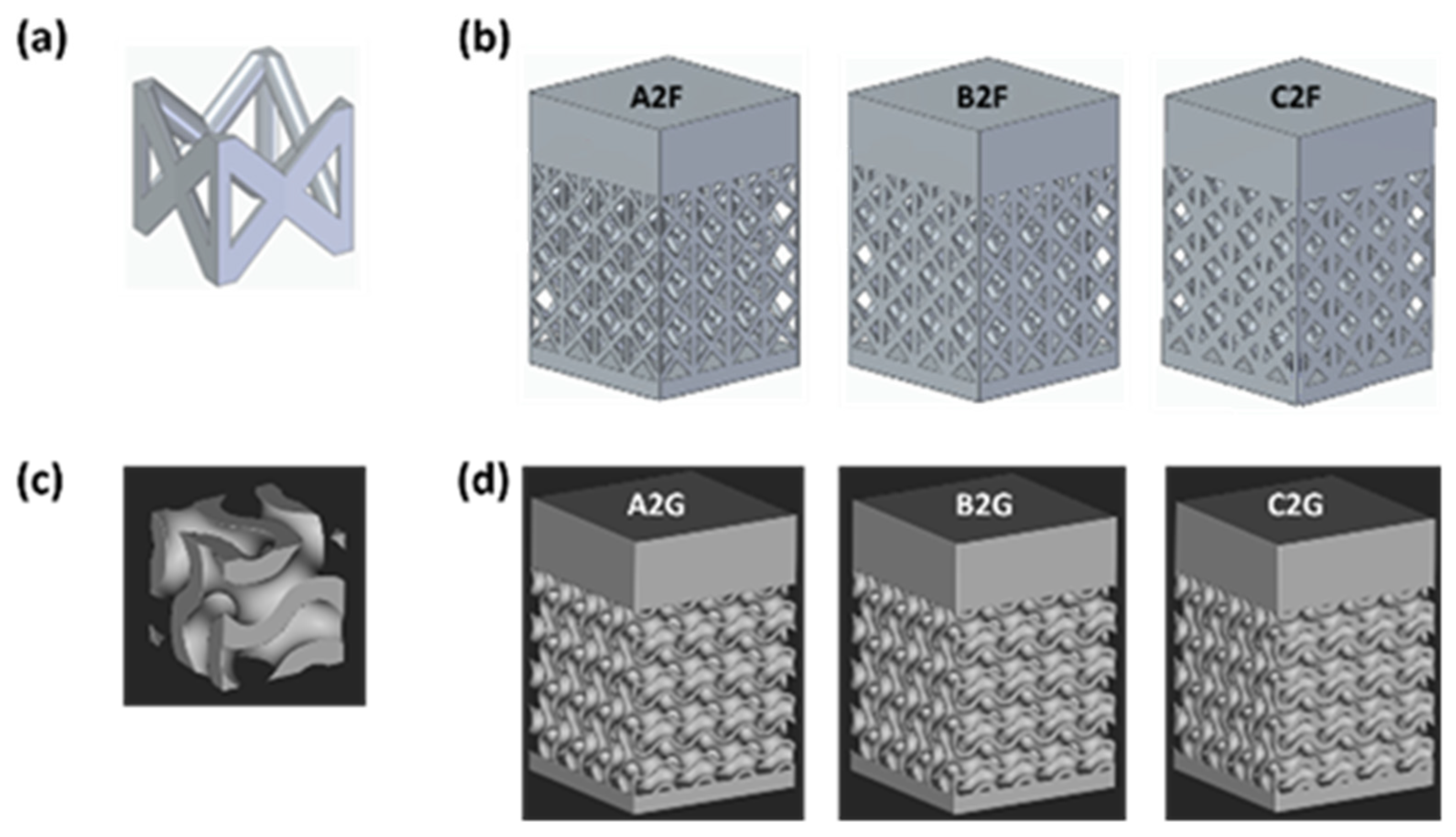
In this study, n-Topology software (nTop 5.12, nTopology, Inc., New York, NY, USA) was used to model lattice specimens with a TPMS Gyroid unit cell pattern, while Siemens NX (v. 2302, Siemens Digital Industries Software, Plano, TX, USA) was used for specimens with an FCCZ unit cell pattern. The lattice specimens featured variable geometric parameters, including cell size and strut diameter (or wall thickness for Gyroid cells). Figure 1a,c present the three-dimensional models of the FCCZ and Gyroid unit cells, respectively. Three lattice specimens were modelled for each cell topology, with unit cell volume varying over time due to changes in strut diameter keeping cell size constant. These variations are listed in the Design of Experiment (DoE) detailed in Table 1. The lattices measured 8 × 8 × 8 mm, with each specimen having a top plate thickness of 3 mm and a bottom plate thickness of 0.8 mm. The lattice structures were not fabricated directly on the construction platform to ensure adequate heat dissipation during the manufacturing process via the bottom plate. The CAD models of the samples with the respective ID code are shown in Figure 1b,d.
Figure 1. CAD models of the unit cell (a) FCCZ and (c) Gyroid and of samples (b) A2F, B2F, C2F and (d) A2G, B2G, C2G.
Table 1. Lattice samples with variable unit cell topology (FCCZ and Gyroid) as a function of unit cell volume.
The failure characteristics and geometrical defects of the samples were examined by scanning electron microscopy (SEM) using a TESCANTM VEGA3® LMU (TESCAN, Brno, Repubblica Ceca) system. Based on these observations and the findings reported in our previous work [16], samples A2F and B2F were excluded from further analysis due to significant geometrical defects and surface damage revealed during preliminary SEM inspections, including incomplete strut fusion, excessive upper-plate warping, and localized material collapse. These configurations, characterized by smaller strut diameters and lower relative densities, were found to be unsuitable for providing the mechanical stiffness and thermal stability required for effective support performance during L-PBF.
Consequently, and in continuity with the earlier study, the present work extends the analysis by introducing the Gyroid lattice as a topological counterpart to the previously investigated FCCZ structure, focusing on the C2F and C2G configurations. These represent the most manufacturable and functionally relevant designs within the experimental matrix. Although the two lattices differ topologically, the FCCZ being a discrete, beam-based structure and the Gyroid a continuous TPMS, the selected specimens share identical geometric parameters (cell size = 2 mm; strut/wall thickness = 0.5 mm). This enables a direct, one-to-one comparison under identical dimensional and processing conditions, isolating the influence of topology on manufacturability, heat dissipation, and defect formation.
Samples A2G and B2G were not characterized, as their inclusion would have hindered a controlled comparison between the two topologies under matching geometric parameters. Therefore, the comparative mechanical and metallographic analyses were focused exclusively on C2F and C2G, ensuring full consistency with the experimental framework established in the previous publication, where only the C2F configuration was characterized in detail, and providing a rigorous basis for assessing how topology governs the performance of L-PBF lattice supports.
It is important to note that the exclusion of the A2 and B2 variants does not compromise the generality of the conclusions. The deformation and defect trends observed in these lower-density structures were consistent with those identified in C2F, confirming that the Gyroid topology systematically exhibits improved heat dissipation and reduced residual stress accumulation across different relative densities. The decision to focus the quantitative comparison on the C2 series thus provides a reliable and representative framework for understanding how topology influences the performance of lattice structures used as internal supports in metallic component fabrication
The exclusion of the lower-density variants does not compromise the generality of the conclusions, as their preliminary observations already confirmed the same deformation and defect trends observed in C2F, thereby supporting the validity and representativeness of the comparative analysis presented here.
FEM simulations of the printing process for these samples were performed using Ansys Additive suite Workbench 2020 R1, which facilitates virtual prototyping under various conditions. The software can simulate mechanical deformations from thermal effects or incorporate explicit thermal phenomena. The simulations used the nominal STL files of the CAD models and L-PBF process parameters, with the model divided into tetrahedrons, following the basic software settings outlined in Table 2. All the process parameters listed in the table and implemented in the simulation are consistent with those employed in the LPBF process, corresponding to the default EOS M290 DMLS parameters for Inconel 718 [16,17]. Although scanning speed, laser power, shielding gas temperature and other process parameters are also known to significantly affect melt-pool stability, heat flow and defect formation in L-PBF, in the present study all process parameters listed in Table 2 were kept constant on purpose in order to isolate the influence of the geometric variables (cell size and strut/wall thickness) and topology (beam-based FCCZ vs. TPMS Gyroid).
Table 2. Setting of simulation parameters, corresponding to the EOS M290 DMLS default process parameters for processing Inconel 718 [16,17].
The thermo-mechanical analyses were performed in ANSYS Additive Workbench (v2020 R1, ANSYS Inc., Canonsburg, PA, USA) using the predefined Inconel 718 material from the Additive Manufacturing Materials Library. This library provides temperature-dependent thermophysical data for powder/solid states (density, specific heat, thermal conductivity) and standard mechanical constants; the curves are used internally by the solver and can be inspected in Engineering Data. No manual modification of the material curves was applied. This approach follows ANSYS guidance and reflects updates made to Inconel 718 datasets in recent releases [18].
In detail, the simulations carried out considered the following phases, printing, cooling and cutting of the part from the build plate, to qualitatively verify that the virtual model in Ansys gives strain and residual stress values comparable to the real ones.
The samples were fabricated on an EOS M250 L-PBF (EOS GmbH, Krailling, Germania) machine using atomised Inconel 718 powder as the feed stock. The following table (Table 3) shows the chemical composition in weight percentage (wt.%) of Inconel 718, as given in the EOS technical data sheet [19].
Table 3. Chemical composition (wt. %) of the Inconel 718 feedstock [19].
The L-PBF process was performed with laser power and scanning speed according to the predefined core-skin scanning pattern as shown in Table 2, where the values of the process parameters set not only for the simulation but also for the sample printing are shown. A laser spot of 0.08 mm was used, and an inert gas atmosphere of argon was established. The heating of the build platform was set to 80 °C.
To compare the manufactured samples with their corresponding simulated models, the top-plate profiles were examined and measured using a Leica DVM6 stereomicroscope. These observations were used to assess the profile shape and quantify the distortion magnitude along the build direction (Z-direction) induced by the manufacturing process.
Two metallographic specimens were extracted from each of the C2F and C2G components by sectioning them along the build direction (YZ plane) using an electric discharge machine (SIMO s.r.l, Ancona, Italy). For each configuration, one specimen was retained in the as-built condition, while the other was subjected to heat treatment to investigate the differences in mechanical and microstructural behavior between the two states. Specifically, solution annealing followed by double aging was performed in accordance with the AMS 2774 and AMS 5662 aerospace material specifications [20,21]. The process involved heating to 954 °C for 1 h, air cooling, reheating to 718 °C for 8 h, furnace cooling to 621 °C, holding for 18 h for precipitation hardening, and finally air cooling to room temperature.
For metallographic analysis, the YZ surfaces of the as-built (C2F-AB, C2G-AB) and heat-treated (C2F-HT, C2G-HT) samples were mechanically polished with silicon carbide paper up to 4000 grit, followed by mirror polishing with diamond paste to 0.25 µm. Optical microscopy (OM) was performed using a Leica DMi8 microscope to examine surface features on the YZ plane and identify defects such as porosity and inclusions. Porosity analysis was carried out using ImageJ software (v. 1.54p, National Institutes of Health, Bethesda, MD, USA) [22] on optical micrographs to quantify pore size and spatial distribution. Quantification was performed separately for the upper plate and lattice regions, distinguishing between lattice nodes and struts, using 15 micrographs per area.
To reveal the alloy microstructure before and after heat treatment, samples were chemically etched at room temperature using a solution composed of 28 mL acetic acid, 28 mL nitric acid, and 44 mL hydrochloric acid.
Further microstructural characterization of the L-PBF Inconel 718 and its evolution after heat treatment was performed by SEM using a ZeissTM Supra 40® (Carl Zeiss AG, Oberkochen, Germany) field-emission microscope equipped with a BrukerTM Quantax Z200® EDS (Billerica, MA, USA) microanalysis system. TEM analyses were conducted using a PhilipsTM CM20® (Philips, Amsterdam, Paesi Bassi) transmission electron microscope operating at 200 kV, fitted with a nitrogen-cooled, double-tilt sample holder. Phase and constituent identification were carried out by selected area electron diffraction pattern (SAEDP) indexing using CaRIne Crystallography 3.1 software. Thin discs for TEM analysis were mechanically thinned to 25–35 µm and subsequently ion-milled using a GatanTM PIPS (Gatan Inc., Pleasanton, CA, USA) with Ar+ at progressively reduced angles from 8° to 4° to achieve electron transparency. To ensure statistical reliability, three discs were examined for each experimental condition.
Vickers microhardness measurements were carried out on all samples under both AB and HT conditions using a QNESS® 60 A+ EVO (QATM GmbH, Golling an der Salzach, Austria) automatic microhardness tester, with an applied load of 300 gF and a dwell time of 10 s, to assess local mechanical behaviour across various surface positions. Measurements were carried out under the same conditions on the upper plate of each specimen. Three systematic indentations were performed every 0.5 mm for 15 times in the YZ plane, covering the entire area of the plate surface. Additionally, further Vickers microhardness tests were carried out along the lattice walls of the C2G-AB and C2G-HT samples and in the lattice struts and nodes of the C2F-AB and C2F-HT samples. In these regions, indentations were spaced 0.25 mm apart to cover the entire area of the struts (C2F) and walls (C2G). Finally, the average hardness obtained for each sample was reported together with its standard deviation.

3. Results and Discussion

3.1. Preliminary Defect Detection and Failure Analysis

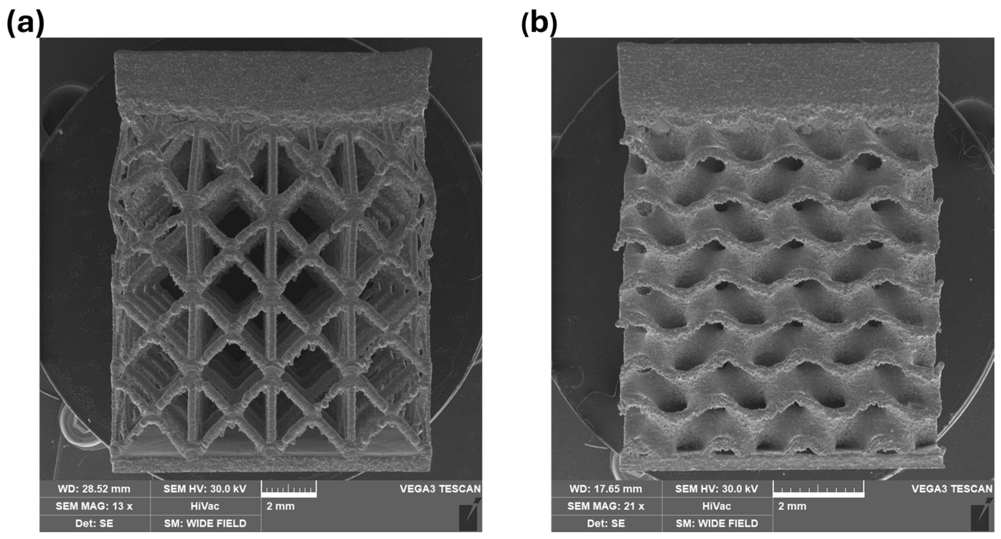
SEM analysis was carried out to evaluate the surface integrity and deformation behavior of the L-PBF Inconel 718 lattice specimens, focusing on the influence of lattice topology under identical geometric parameters. Figure 2 compares the as-built morphologies of two lattice specimens, called B2F and B2G.
Figure 2. SEM images of lattice specimens with identical cell size and wall/strut thickness but different topologies: (a) B2F sample with FCCZ beam-based lattice structure and (b) B2G sample with continuous Gyroid TPMS topology, showing reduced strut discontinuities and smoother surface morphology.
Although the two lattices differ in topology, the FCCZ being a beam-based, stretch-dominated structure and the Gyroid a smooth, surface-based TPMS, both were fabricated using the same process parameters. As already documented in our previous work [16], the B2F specimen exhibited several manufacturing-related defects, including pronounced top-plate warping, strut discontinuities, and localized node bulging due to excessive thermal accumulation and insufficient heat dissipation during the printing process. Such defects are again visible in Figure 2a, reproduced here for comparison.
Conversely, the B2G specimen shown in Figure 2b displayed significantly fewer defects. The continuous nature of the Gyroid topology provided improved heat flow and stress redistribution during solidification, resulting in fewer discontinuities and a smoother surface morphology compared to the beam-based FCCZ lattice. Nevertheless, some degree of top-plate warping is still present, albeit less pronounced than in B2F, suggesting that even the TPMS architecture was not fully effective in mitigating thermally induced distortions. Hence, neither of these topologies, in their current geometrical configuration, can be considered optimal for supporting overhanging structures or efficiently dissipating heat during L-PBF.
To further highlight these differences, Figure 3 compares the C2F and C2G specimens. The SEM image of the C2F sample (Figure 3a) shows a limited yet still noticeable warping of the upper plate, less pronounced than in the B2F specimen, along with minor strut defects and local discontinuities, consistent with previous observations for beam-based lattices [16]. Among the beam-based configurations, the C2F lattice demonstrated the most stable behavior, primarily due to its higher volume fraction, which improved thermal management and reduced deformation during the L-PBF process. For this reason, it was selected for further microstructural and mechanical characterization. In contrast, the C2G specimen shown in Figure 3b exhibits a more uniform morphology, smoother strut surfaces, and an absence of discontinuities within the lattice network. The continuous geometry of the Gyroid topology enhances structural stability and promotes more efficient heat dissipation, thereby minimizing thermal stresses and associated warping during fabrication.
Figure 3. SEM comparison between specimens C2F (a) and C2G (b) fabricated with identical geometric parameters (cell size and wall/strut thickness). The Gyroid-based C2G exhibits fewer surface defects, lower warping, and enhanced structural stability of the top plate compared to its beam-based counterpart.
Considering these findings, the subsequent metallographic and mechanical characterization was focused exclusively on the C2F and C2G samples, which share identical geometric parameters but represent fundamentally different topologies.
SEM images of samples A2F and A2G are not included to avoid redundancy. These specimens exhibited similar or even more pronounced defects than B2F and B2G, mainly due to their lower volume fractions and higher geometric compliance and were therefore excluded from further analysis.

3.2. FEM Analysis

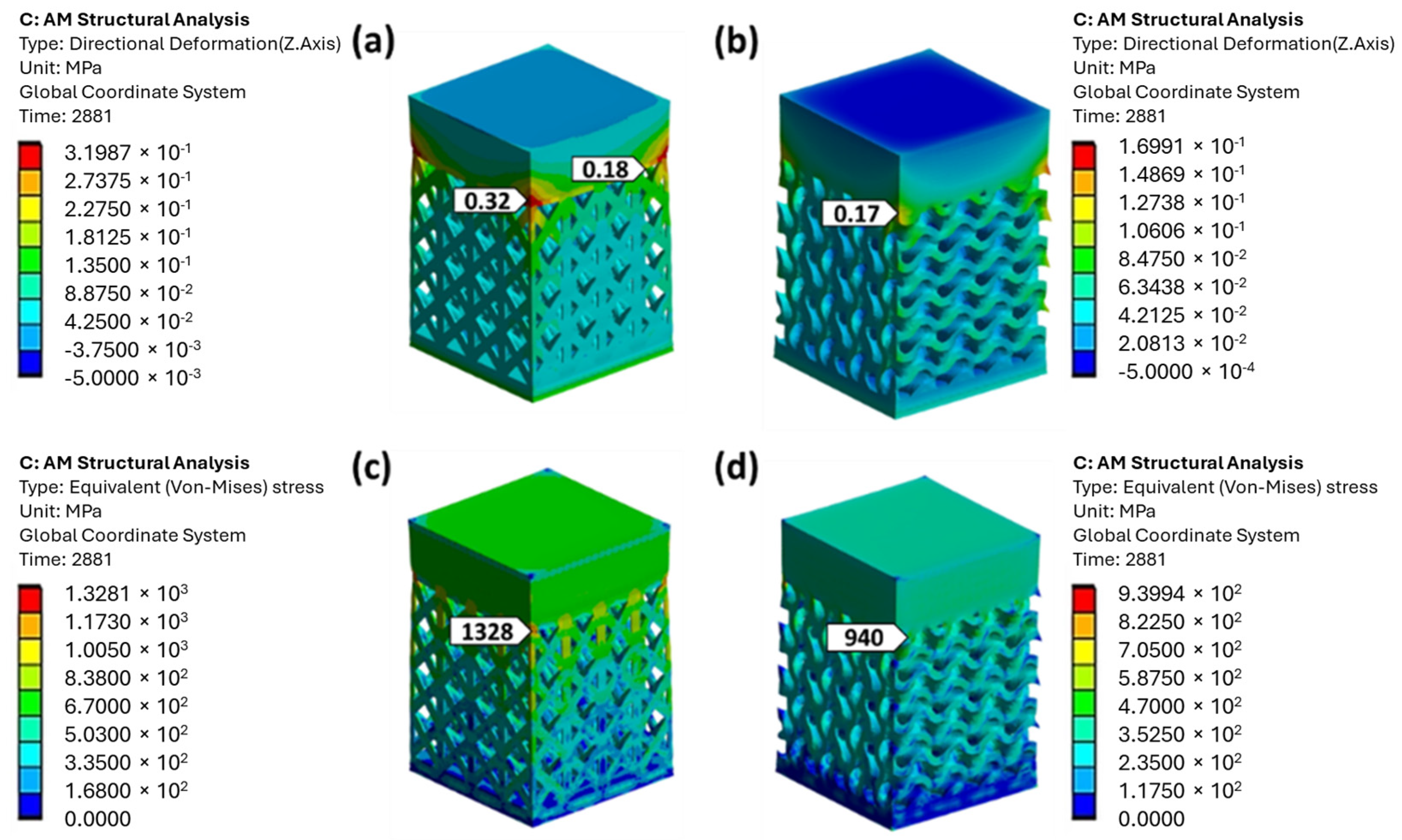
Figure 4a,b presents the results of the FEM analysis conducted using Ansys® Workbench 2020 R1. The results are expressed in terms of directional deformations measured along the z-axis, at the end of the printing phase and after the removal of the component from the build plate. Specifically, Figure 4a,b highlight markers indicating the maximum directional deformation along the z-axis (in mm) measured in the interface region between the lattice structure and the upper plate, particularly near the edges, where significant distortion of the plate is observed. The maximum directional deformation recorded is 0.32 mm for the C2F sample, while the C2G sample exhibits a maximum deformation of 0.17 mm. It is therefore evident that the C2F sample exhibits the most significant distortions, as it has a lattice structure that is more compliant than that of the C2G sample. Consequently, it is less effective at dissipating the heat generated during the printing process. It should be noted that the simulation results for the C2F sample have already been presented and discussed in [16].
Figure 4. FEM results showing (a,b) the maximum directional deformation (along the z-axis) expressed in mm for samples C2F and C2G, respectively, and (c,d) the Von Mises equivalent stress (MPa) for C2F and C2G after removal from the build plate.
After the components were removed from the build plate, the maximum stress reached was approximately 1328 MPa for the C2F sample (Figure 4c) and 940 MPa for the C2G sample (Figure 4d), with both samples showing this peak stress in the interface region between the lattice structure and the upper plate. While the maximum stress observed in the C2G sample remains acceptable, as it does not exceed the yield strength of Inconel 718, which ranges from 724 MPa to 1241 MPa, the C2F sample exceeds this yield strength, indicating the possibility of permanent plastic deformation. This could increase the risk of cracks or defects in the affected area, especially if there are local variations in process conditions or microstructure. In addition, the FEM-predicted residual stress magnitudes are not only used to interpret the deformation mechanisms of the two topologies, but they also provide quantitative guidance for downstream process decisions. In practice, these stress levels can be used to identify whether standard stress relief cycles are sufficient, or whether adjusted dwell times or modified step-solution treatments may be required. Therefore, in the present study, the FEM output should be regarded as a process-planning tool, enabling a rational definition of post-processing strategies rather than only a descriptive comparison of the two topologies.
The higher stress concentration observed in the C2F sample can be directly attributed to the intrinsic characteristics of its beam-based FCCZ topology, which promotes localized heat accumulation and mechanical constraint at the nodal junctions where multiple struts intersect. These nodes act as both thermal and mechanical concentrators, generating steep temperature gradients during layer deposition and inducing nonuniform solidification shrinkage. Consequently, the regions surrounding the node–plate interface exhibit the highest residual stresses and distortions, as also predicted by the FEM model.
This behavior is consistent with the experimental observations discussed in Section 3.4, where the C2F lattice exhibited a higher density of keyhole-type porosity and local melt-pool instabilities, typically occurring near nodal regions identified as stress hot spots in the simulation. As reported in our previous study [16], such localized overheating and steep thermal gradients can drive the process into a partial keyhole regime, in which recoil pressure fluctuations and vapor-cavity collapse result in gas entrapment and pore formation [23,24,25]. These keyhole-type pores, frequently observed at or near the FCCZ nodes, are the most critical regions for crack initiation and distortion during cooling, coincide with the areas of maximum residual stress predicted by the FEM model. This correlation further reinforces the strong coupling between thermal imbalance, stress accumulation, and defect formation within the FCCZ architecture [26].
In contrast, the Gyroid topology—characterized by a continuous, curvature-smooth minimal surface-promotes more uniform heat dissipation and stress redistribution throughout the build. Its continuous morphology eliminates discrete junctions and mitigates localized thermal peaks, thereby minimizing recoil-pressure instabilities within the melt pool [27]. Consequently, both FEM simulations and experimental results consistently show that the C2G specimen develops lower residual stresses (approximately 940 MPa), experiences smaller distortions, and exhibits no keyhole-type porosity, confirming its superior thermal stability and manufacturability under identical process parameters.
These findings reinforce the physical connection between topology-dependent heat flow, stress evolution, and defect formation, establishing a coherent link between numerical predictions and microstructural evidence.
The superior manufacturability of the Gyroid topology can be attributed to its continuous, triply periodic minimal surface, which provides an uninterrupted heat-conduction path during L-PBF compared with the discrete, node-dominated load paths of the FCCZ lattice. In practice, the Gyroid’s curvature-smooth surface distributes laser-induced heat more uniformly both in-plane and through the build thickness, mitigating steep local temperature gradients and reducing the amplitude of thermal cycles at feature junctions. This results in lower residual stress accumulation, reduced distortion, and a more stable melt pool, in which Marangoni convection and recoil-pressure oscillations are less likely to destabilize the surface and trigger a transition to the keyhole regime.
Conversely, in the FCCZ geometry, the discrete strut nodes concentrate both heat flow and mechanical constraint, promoting localized overheating and keyhole-type pore nucleation when the energy input becomes excessive (Section 3.4). These trends are consistent with previous studies reporting that TPMS/Gyroid surfaces enhance thermal spreading and melt-pool stability, whereas steep thermal gradients amplify Marangoni-driven instabilities and keyhole pore formation during L-PBF [28,29,30,31,32,33].

3.3. FEM Analysis vs. Experimental Results

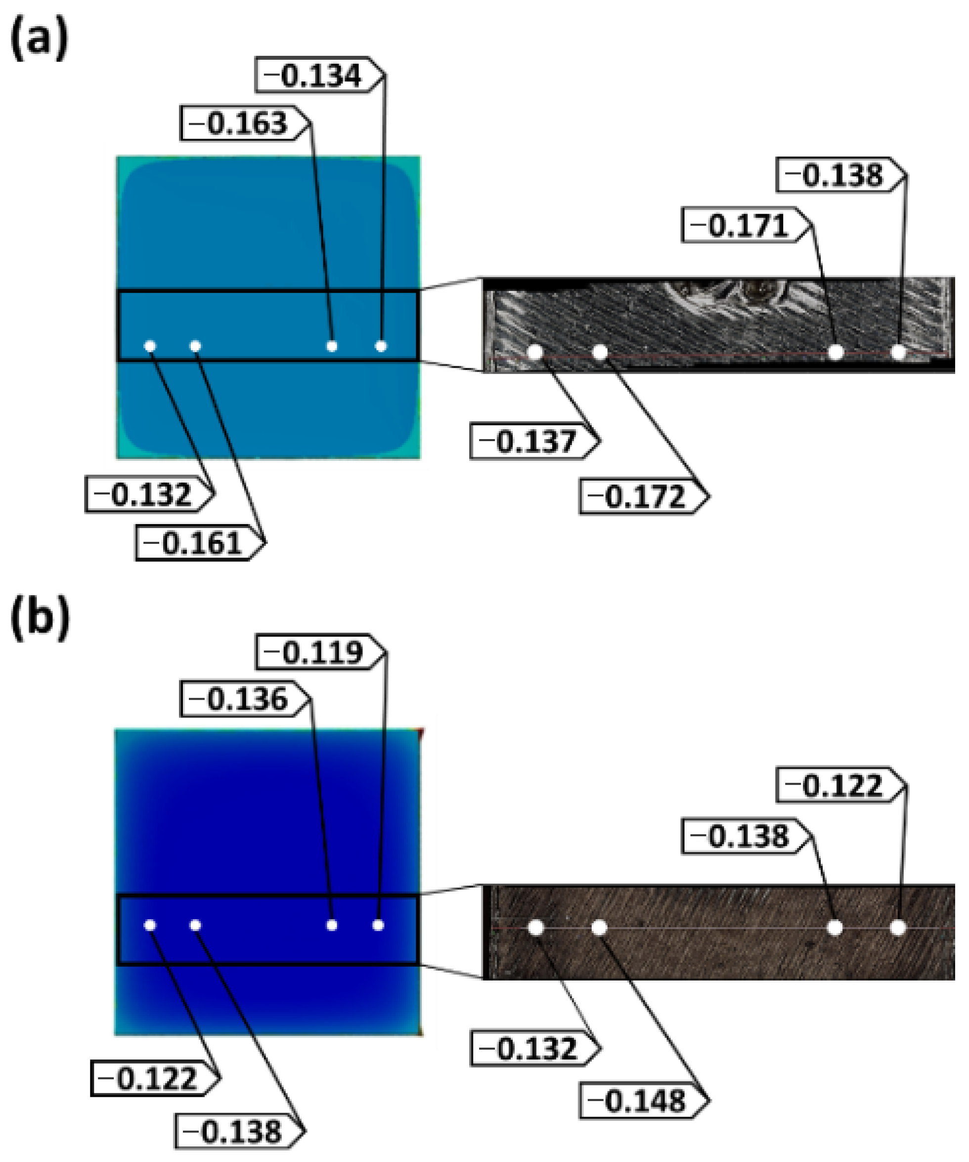
The comparison between the simulated models and the printed geometries was conducted through stereomicroscope observations. The deformation profile of a portion of the upper plate was extracted, and directional deviations were measured at specific points on the upper plate along the XY plane. The results, presented in Figure 5, demonstrate a robust correlation between the simulated models and the real components regarding both the deformation trend and the numerical values of directional deformations (along the z-axis) measured in the XY plane of the upper plate, confirming the reliability of the software used. In both the C2F and C2G samples, a slight curvature of the plate towards the negative Z direction was observed, resulting in compression of the upper surface. A reversal in the deformation trend is observed, with the deformation increasing in magnitude from the central area towards the edges of the plate. The extent of deformation was quantified at specific points on the plate in both the simulated models and the corresponding points on the actual samples. The upward curvature in the negative Z direction of the upper plate in the C2F sample (Figure 5a) is more pronounced than that observed in the upper plate of the C2G sample (Figure 5b), as indicated by the deformation values expressed in mm. The increased distortion observed in the C2F sample can be attributed to its less massive FCCZ lattice structure, which is less effective at dissipating the heat generated during the manufacturing process than the Gyroid structure.
Figure 5. Comparison of directional deformations along the z-axis, measured in millimetres, between the Ansys model and the real geometry (stereomicroscope measurements) for the upper plate of samples (a) C2F and (b) C2G.

3.4. Assessment of Microstructural and Mechanical Behaviour in As-Built and Heat-Treated Conditions

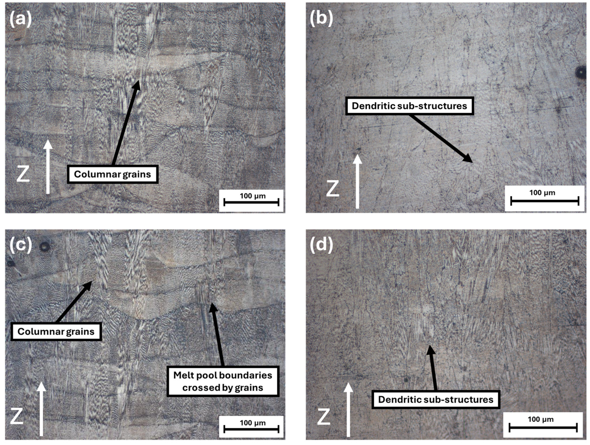
Figure 6 presents the optical micrographs acquired along the YZ plane from the upper plates of both lattice configurations in the as-built (AB) and heat-treated (HT) conditions: (a) C2F-AB, (b) C2F-HT, (c) C2G-AB, and (d) C2G-HT.
Figure 6. Optical micrographs of the upper plate (YZ plane) of samples: (a) C2F-AB and (c) C2G-AB, displaying epitaxial grain growth across melt pool boundaries; (b) C2F-HT and (d) C2G-HT, showing columnar grains formed after heat treatment with partially retained dendritic substructures.
The upper plates of both samples exhibit very similar microstructural features before and after heat treatment. In the as-built condition, both C2F and C2G display the characteristic arc-shaped melt-pool boundaries resulting from the laser scan strategy, with partially overlapping pools and columnar grains aligned with the build direction (Z). The morphology of the melt pools and the cellular dendritic structure within the γ matrix are nearly identical between the two samples, confirming that the top-plate solidification behavior is primarily governed by the process parameters rather than by the underlying lattice topology.
After the AMS 2774 + AMS 5662 heat treatment (Figure 6b,d), both samples show partial recrystallization and a reduction in melt-pool contrast, while some elongated columnar grains are still visible. The microstructures of C2F-HT and C2G-HT remain largely comparable, indicating that the thermal response and recrystallization kinetics are equivalent under the applied cycle. These observations demonstrate that the heat treatment promotes similar microstructural evolution in both lattice types, supporting the validity of the subsequent comparative analyses.
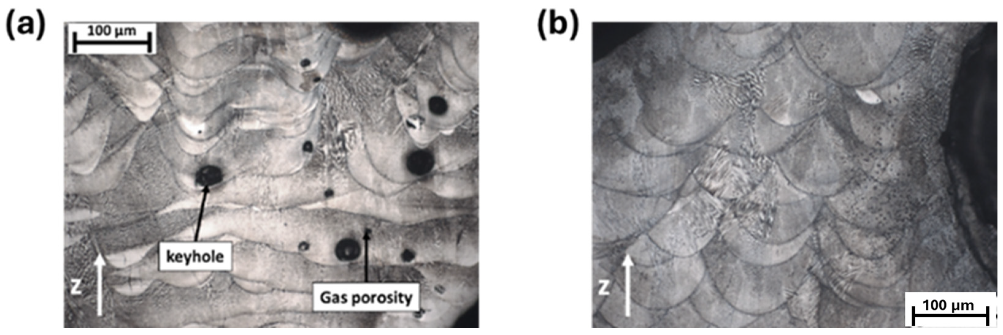
The micrograph along the YZ plane in a region of the lattice structure of the C2F-AB sample (Figure 7a) shows that the porosities, although randomly distributed along the whole lattice, are more diffuse and characterised by larger voids in the area close to the nodes, due to the rapid change in thermal diffusivity during the production process as different struts are joined together. This result is in line with expectations, since the sudden changes in cross-sectional area (YZ plane) that occur during the printing phase of the component lead to significant instability phenomena in the melt pool. The porosities are localised within the melting pools, as can be seen from the micrographs in Figure 7a, and most of these are keyhole-type porosities [16]. The formation of keyhole-type melting pools is usually due to excessive energy being absorbed by the powder bed, resulting in the laser beam penetrating too deeply. The formation of deep melting pools can also be attributed to Marangoni flow, which is melt flow from the hot centre to the edges of the pool due to the difference in surface tension induced by the strong thermal gradient. This was also confirmed by the work of Salem et al. [34], where microstructural analysis showed deep melting pools under keyhole conditions at high laser powers and relatively low scan speeds. The presence of few small spherical porosities can also be detected, which is mainly due to the gas trapped in the powder bed during the production process [16]. Figure 7b shows that sample C2G-AB exhibits no significant porosity near the lattice region.
Figure 7. Micrographs showing defects in terms of porosity observed along the YZ plane in a region of the lattice structure of the samples (a) C2F-AB and (b) C2G-AB.
To quantitatively support the qualitative observations reported in Figure 6 and Figure 7, a detailed porosity analysis was conducted on both C2F and C2G samples in the as-built (AB) and heat-treated (HT) conditions. The measurements were performed using ImageJ software on high-resolution optical and micrographs acquired from both the upper plate and the lattice regions.
The results are summarized in Table 4, which reports the average porosity percentages and standard deviations for each configuration, along with the corresponding regions of analysis.
Table 4. Quantitative evaluation of porosity (area percentage) in C2F and C2G samples before and after heat treatment.
The variation in defect rates in L-PBF lattice samples fabricated with identical process parameters can be attributed to differences in lattice cell geometries and their impact on heat distribution, laser penetration, and residual stresses. Moreover, the ImageJ analysis confirmed that while the C2F sample exhibits both “keyhole-type” porosities (average area approximately 792 ± 217 μm2) and smaller spherical gas-trapped pores (approximately 50 ± 7 μm2), the Gyroid structure (C2G) shows a more uniform and defect-free morphology, with no evidence of keyhole voids. This behavior is attributed to the continuous minimal-surface topology of the Gyroid, which promotes a more uniform energy distribution and melt-pool stability during the L-PBF process. The smoother curvature and absence of sharp intersections enhance heat dissipation, minimizing localized overheating, and thereby suppressing the formation of keyhole-type defects typically associated with excessive local energy input.
These quantitative results, together with the microstructural observations, confirm that the Gyroid topology exhibits superior manufacturability and process stability compared to the FCCZ lattice under identical processing conditions.
The values obtained indicate that the porosity levels in the Gyroid lattice are significantly lower than in the beam-based FCCZ structure, particularly in the lattice regions, where the total void fraction is reduced by approximately 40% compared with C2F. For both topologies, the difference between the AB and HT conditions is minimal, confirming that the standard AMS heat treatment does not significantly influence the overall density, as already observed in the previous study [16].
Additionally, energy density and laser penetration vary between lattice geometries. The FCCZ structure tends to cause irregular laser absorption, whereas the more massive Gyroid structure achieves more uniform energy distribution. Residual stresses, typically higher in intricate geometries such as FCCZ, further contribute to defect formation, while Gyroid structures distribute these stresses more evenly, thereby reducing defect occurrence.
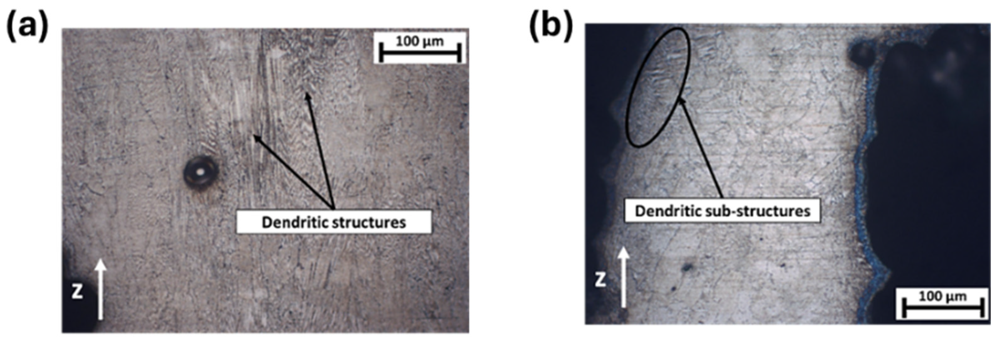
In the C2F sample, heat treatment resulted in differential recrystallization within the same component. This behavior arises from the different thermal inertias of the solid plate and the lattice structure, which cause variations in heat distribution during treatment. The lattice, having a larger exposed surface area than the solid upper plate, likely experienced different heating and cooling rates. As shown in Figure 8a, the microstructure within the lattice region of the C2F-HT sample exhibits less recrystallization and retains more non-equilibrium dendritic features compared with the upper plate microstructure shown in Figure 6b. These results, consistent with both as-built and heat-treated conditions, were previously documented and discussed in detail in [16].
Figure 8. Microstructures along the YZ plane of the lattice regions in (a) C2F-HT and (b) C2G-HT samples, showing heat-treatment-induced columnar grains with partially retained dendritic substructures.
This uneven recrystallization influences the material’s microstructure and mechanical response, potentially affecting the overall performance of the component. For the same reasons, similar microstructural differences are observed between the C2F-HT and C2G-HT samples. Specifically, the heat treatment induced a lower degree of recrystallization in the C2F lattice, Figure 8a, compared with the lattice region of the C2G-HT sample, Figure 8b, indicating that the FCCZ-based lattice exhibits a distinct thermal response during heat treatment and a greater retention of dendritic structures.
Figure 9a presents a low-magnification SEM image of the upper plate area of the C2G-AB sample, revealing a very fine cell-dendritic microstructure. In this region, the secondary arms of the dendritic structures are entirely suppressed, allowing only the primary arms to develop. As observed in the micrographs in Figure 6c and Figure 7, as well as in the SEM image in Figure 9a, the growth directions of the dendrites are not perfectly parallel to the build direction but are instead inclined by a few degrees. Additionally, within a single melt pool, cell dendrites can grow in various directions and may be interrupted by adjacent cell dendrites, a phenomenon also reported in the literature by Deng et al. [35]. The variation in the size and orientation of these solidifying cell substructures is driven by the high temperature gradient and rapid cooling rate characteristic of the L-PBF process. As a result, the growth orientation of the dendrites aligns with the direction of the maximum temperature gradient. This indicates that the temperature field within the melt pool is highly complex, with turbulent motion inducing a reversal of the thermal gradient. Figure 9b presents a bright-field (BF) TEM image of sample C2G-AB, revealing thin cell substructures with a high density of dislocations concentrated along the cell walls. The dark, irregularly shaped block-like precipitates observed near the grain boundaries, as indicated by the arrows in Figure 9b, have been identified as Laves phases.
Figure 9. (a) SEM image showing melt pools and the orientation of columnar dendritic substructures along the YZ plane; (b) TEM image of the C2G-AB sample along the YZ plane, highlighting the presence of Laves phases.
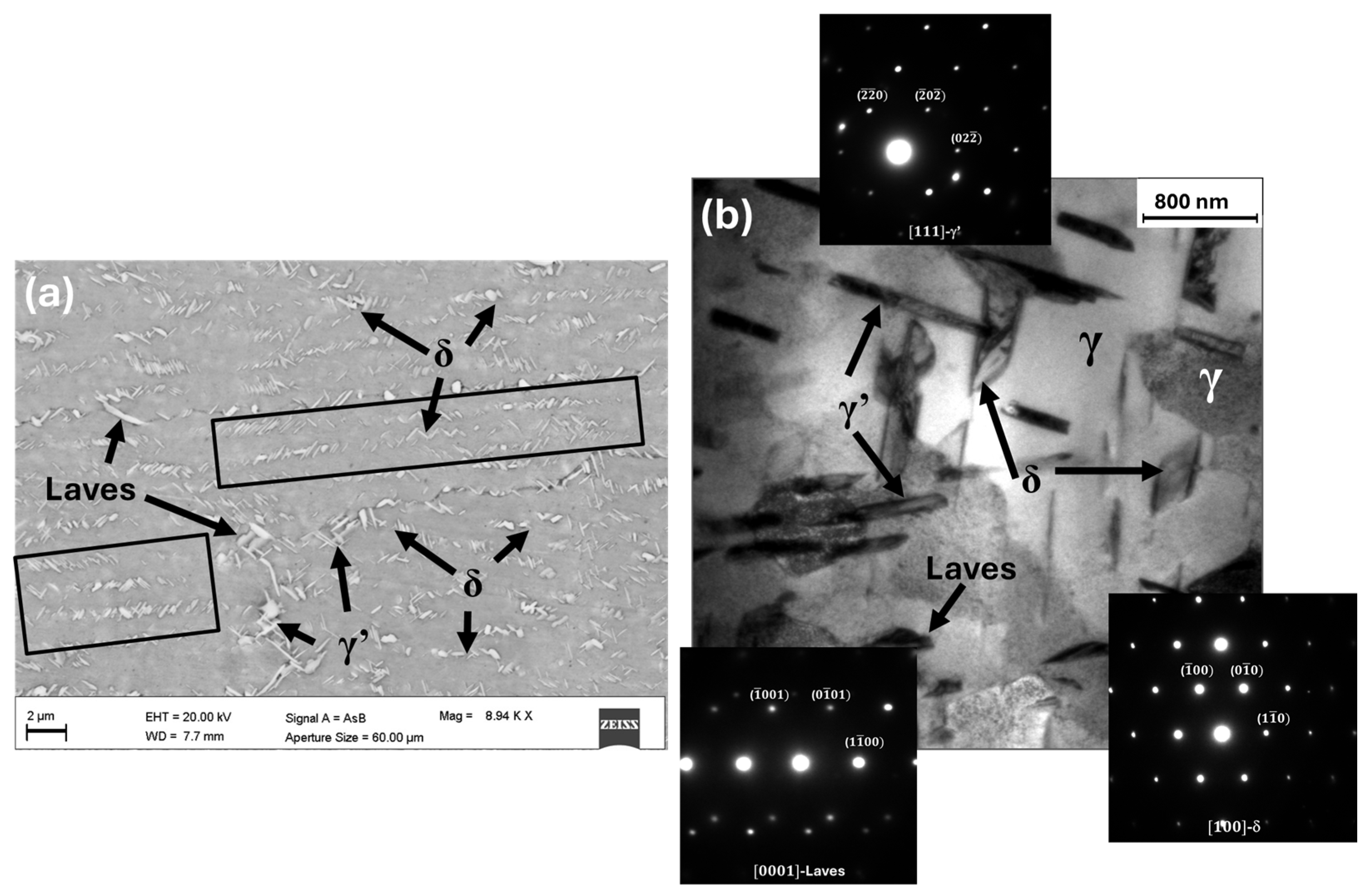
The SEM image in Figure 10a illustrates that in the C2G-HT sample, compared to the C2G-AB sample, the boundaries of the melt pools and many directional dendritic microstructures have been dissolved. Several needle-like δ (Ni3Nb) phases are present within the grains and along the grain boundaries, with some precipitates also found in the interdendritic regions, as indicated by the black rectangles in Figure 10a. This observation aligns with findings reported in the study by Li et al. [36]. The formation of interdendritic δ precipitates preserves the visibility of the intragranular columnar structure after heat treatment. SEM imaging also identifies other precipitated phases, likely γ’ (Ni3 (Al, Ti)) phases, which may form within the γ matrix both inside grains and near grain boundaries, with an acicular morphology. The γ’ phases reinforce the γ matrix, while the δ phases, precipitating at grain boundaries, act as barriers to dislocation movement, enhancing resistance to deformation at high temperatures and under sustained loads. However, the persistence of undissolved Laves phases in the matrix after the AMS-standard heat treatment has critical implications for the long-term performance of L-PBF Inconel 718 components intended for high-temperature service. Laves phases, typically rich in Nb and segregated at interdendritic regions, act as brittle intermetallic compounds that locally deplete Nb from the γ matrix, thereby reducing the formation of strengthening γ’ and γ” (Ni3Nb) precipitates [37]. Their presence therefore limits complete precipitation hardening and leads to heterogeneous mechanical behavior, particularly in areas subjected to cyclic or thermally induced loading.
Figure 10. (a) SEM images of the C2G-HT sample microstructure, highlighting the δ, γ’, and Laves precipitate phases; (b) Low-magnification TEM bright-field (BF) image of the C2G-HT sample along the YZ plane, showing the γ austenite cellular substructure and the precipitated needle-like δ and γ’ phases, as well as block-shaped Laves phases.
From a mechanical standpoint, Laves phases act as crack initiation sites under tensile or cyclic stress, promoting fatigue-crack propagation along interdendritic boundaries where residual micro-segregation persists. Several authors have shown that these phases can significantly reduce fatigue life and creep resistance by acting as barriers to dislocation glide and by concentrating local stress at brittle-matrix interfaces [36,38]. Furthermore, in lattice or thin-wall structures such as those considered here, their effect can be magnified because of the higher surface-to-volume ratio and the presence of stress concentrators inherent to geometry.
These observations of precipitated phases in the C2F-HT sample partially align with the findings presented in the research by Li et al. [36] and Zhang et al. [38]. Consequently, this microstructure cannot be considered ideal. The TEM bright-field (BF) micrograph in Figure 10b, together with the corresponding SAED patterns shown as the inset, confirms the identification of the precipitated phases. This method is essential for distinguishing phases based on their crystal structure, as many of the precipitates observed in SEM are morphologically and compositionally similar. The cellular structures highlighted in both light and dark colours in Figure 10b represent the γ matrix, but with different crystallographic orientations.
SEM and TEM analyses performed on a localized area of the upper plate of sample C2F revealed microstructural features identical to those observed in the corresponding region of sample C2G. For this reason, the related results are not reproduced here, as they have already been comprehensively presented and discussed in [16].
The results presented in this work confirm that the standard AMS 2774 + AMS 5662 heat-treatment schedule, although industrially relevant and effective in promoting precipitation hardening, was not sufficient to achieve complete homogenization and dissolution of the interdendritic Laves phases in L-PBF-fabricated lattice structures. This limitation arises from the unique thermal history of additively manufactured components, characterized by extremely rapid solidification rates, strong micro-segregation, and the formation of fine cellular dendritic substructures, which differ substantially from those of conventionally processed materials for which AMS specifications were originally defined.
In the present specimens, residual Laves and δ phases persisted even after the standard solution plus double-aging cycle, particularly within the lattice regions exhibiting higher surface to volume ratios and faster local cooling during the build. As discussed in the previous paragraphs, the presence of such retained phases may locally deplete Nb from the γ matrix, thus limiting the precipitation of strengthening γ” and γ” phases during aging and potentially reducing the alloy’s creep and fatigue resistance under service conditions.
Although the AMS treatment remains the most practical route for ensuring process standardization in aerospace manufacturing, several recent studies have demonstrated that slightly modified post-processing routes can better accommodate the fine-scale segregation and sub-grain features typical of L-PBF materials. These include the introduction of a homogenization step at 1065–1080 °C for 1–2 h before solution annealing [15,36,38,39,40] or an increase in the solution temperature to approximately 980–1000 °C to promote more complete dissolution of Nb-rich phases without significant grain growth. In addition, combining Hot Isostatic Pressing (HIP) with the subsequent double-aging cycle has been reported to effectively reduce both porosity and micro-segregation.
Accordingly, while the present study deliberately employed the AMS-standard treatment to preserve industrial comparability, the results suggest that a slightly modified heat-treatment route, including a brief homogenization or HIP step before the conventional double aging, could enhance microstructural uniformity and mechanical performance in L-PBF lattice structures. Future work will explore such optimized post-processing strategies to achieve full Laves dissolution and improved long-term stability of additively manufactured Inconel 718 supports.
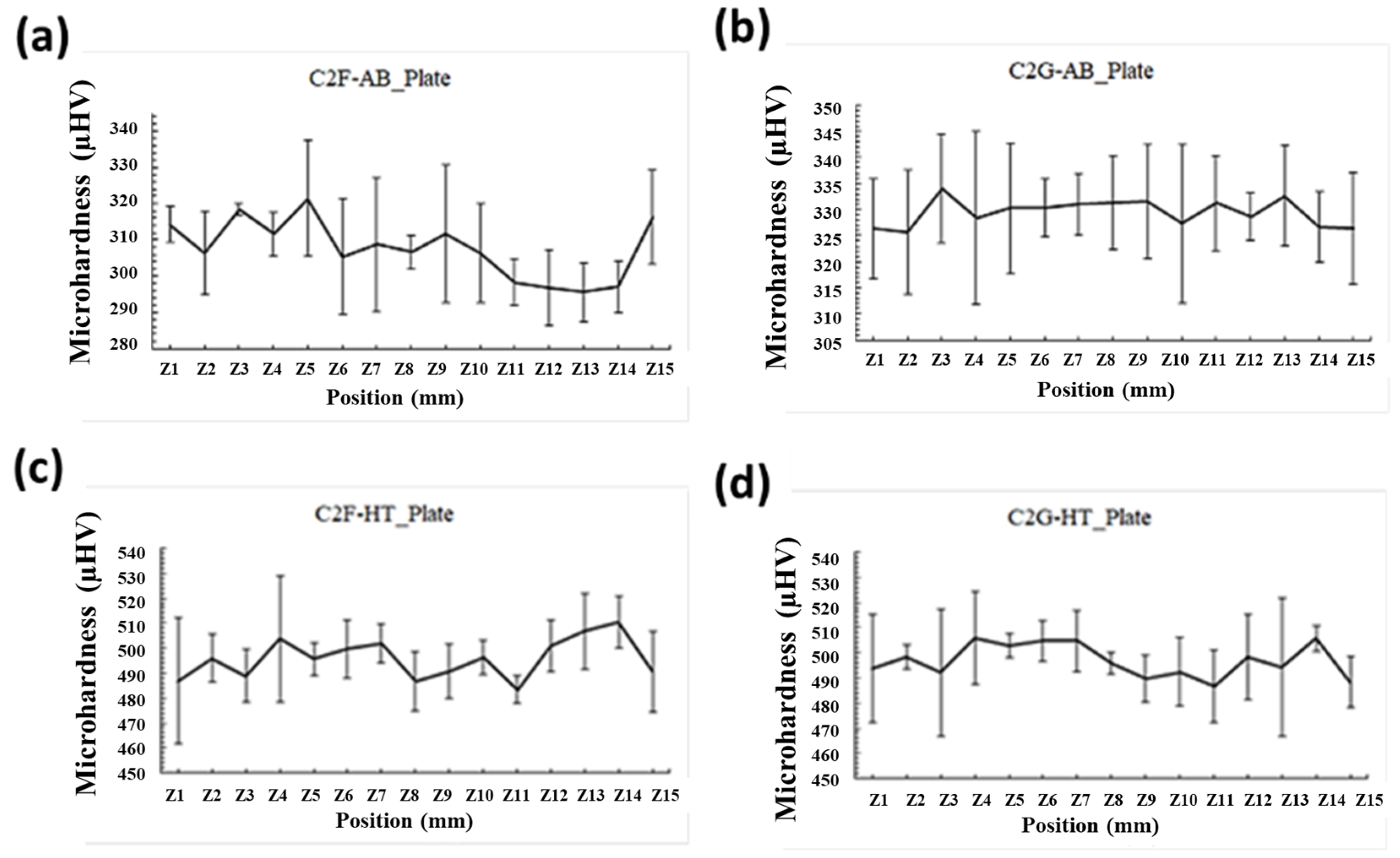
Vickers microhardness characterization was conducted on the YZ plane of the C2F and C2G samples in both the AB and HT conditions. For each sample, microhardness measurements were conducted on both the upper plate and the lattice structure. Figure 11 displays the microhardness profiles (µHV, 300 gf) measured on the upper plate along the build direction (YZ plane) of the C2F-AB (Figure 11a), C2G-AB (Figure 11b) C2F-HT (Figure 11c) and C2G-HT (Figure 11d) samples. For the C2F-AB sample, the average microhardness on the upper plate is 308 ± 16 HV, with values higher near the edge and interface with the lattice and lower towards the core [16]. The C2G-AB sample shows a higher average microhardness of 329 ± 12 HV. In the HT condition, both C2F and C2G samples exhibit similar microhardness values of approximately 497 ± 10 HV. The greater standard deviation in AB samples, compared to HT ones, is due to a less uniform microstructure, residual stresses, printing defects, and thermal fluctuations. Heat treatment enhances microstructural uniformity, reduces residual stresses, and minimizes defects, resulting in lower variability and standard deviation in microhardness.
Figure 11. HV microhardness profiles (300 gf) of the upper plate collected in the growth direction of (a) C2F-AB, (b) C2G-AB, (c) C2F-HT and (d) C2G-HT samples.
Figure 12a presents a column chart comparing average microhardness values and their standard deviations along the YZ plane for C2F-AB and C2F-HT samples, focusing on the upper plate, lattice nodes, and struts. Both AB and HT samples show distinct peaks in average microhardness, characterized by significant standard deviations, especially within the lattice structure. This variability is due to the presence of numerous pores introduced during manufacturing, particularly in the lattice structure, including the struts and nodes. Figure 12b shows a bar chart of average microhardness values and standard deviations for the C2G sample along the upper plate and three lattice walls (one central and two near the edges) in the YZ plane, before and after heat treatment. The relatively higher standard deviation observed for the C2F samples, particularly within the lattice regions, can be attributed to their heterogeneous microstructural features, such as the presence of melt-pool boundaries, partially recrystallized zones, and variable heat-affected regions around the struts. In contrast, the C2G samples, characterized by a continuous wall morphology and more homogeneous heat distribution, exhibited lower variability in hardness. This behavior further confirms the superior thermal stability of the Gyroid topology during the L-PBF process, resulting in more uniform precipitation strengthening after heat treatment.
Figure 12. Comparison of average microhardness values with standard deviations obtained along the YZ plane for (a) C2F-AB and C2F-HT samples, measured on the upper plate, lattice nodes, and struts, and (b) C2G-AB and C2G-HT samples, measured on the upper plate and on the lattice near the outer walls (left and right) and the central wall.
The increase in hardness observed in the heat-treated samples compared to the as-built condition is primarily attributed to significant phase precipitation resulting from heat treatment. TEM micrographs (Figure 10b) identify the predominant δ phases, with γ’ phases also contributing significantly. The γ’ phases precipitate during the double aging process at 718 °C and 621 °C, strengthening the material and enhancing its hardness. Similar findings have been reported by Deng et al. [35] and Zhang et al. [38]. Implementing a high-temperature homogenization step or reducing the aging duration could promote the precipitation of the γ” phase. Further studies are required to assess whether these modifications may enhance mechanical properties, including microhardness. Nevertheless, since this work strictly followed the heat treatment procedures prescribed by Aerospace Material Specifications AMS 2774 and AMS 5662, no conclusive evidence can be drawn beyond the observations reported in the referenced literature [16]. Additionally, Chamanfar et al. [37] observed that a small amount of δ phase can inhibit grain growth by pinning grain boundaries, which enhances strength and hardness through grain boundary strengthening [37]. However, excessive δ phase content can reduce strength, as it depletes Nb and hinders the precipitation of γ” strengthening phases.
It is important to emphasize that the mechanical assessment presented in this study is based exclusively on Vickers microhardness measurements, which provide a localized, yet statistically representative indication of the strengthening effects associated with γ′ phase precipitation following the AMS 2774 + AMS 5662 heat-treatment cycle. While hardness does not directly quantify global mechanical properties, such as tensile or fatigue behavior, it remains a sensitive metric for evaluating microstructural consistency and the precipitation response within L-PBF Inconel 718.
The comparable hardness levels measured across the upper plates and lattice regions of both the C2F and C2G samples indicate that the applied heat treatment promoted a similar degree of microstructural stabilization in both topologies. This finding demonstrates that, despite differences in geometrical configuration and heat dissipation during the L-PBF process, both architectures achieved a comparable degree of strengthening. Consequently, the microhardness results provide valuable insight into the effectiveness of the thermal treatment and the intrinsic uniformity of the alloy’s microstructural response.
Future work will incorporate nanoindentation and miniaturized tensile testing to establish quantitative correlations between local hardness, yield strength, and strain-hardening behavior within the lattice structures. Nonetheless, the current microhardness already offers meaningful insight into the microstructural response and strengthening potential of L-PBF Inconel 718 lattice architectures under industrially relevant processing conditions.

4. Conclusions

This study extended the previous investigation on Inconel 718 lattice structures fabricated via L-PBF [16], focusing on a comparative assessment between beam-based FCCZ and TPMS-based Schoen Gyroid architectures. Building upon earlier results, where the FCCZ structure demonstrated suitability as an internal support for upper plates under specific geometric constraints, the present work broadened the analysis to include the Gyroid topology, with the aim of assessing its potential as an advanced support structure for complex geometries.
Finite Element Method (FEM) simulations performed in Ansys confirmed the capability of the software to accurately predict thermal and mechanical deformations both during the L-PBF process and after removal from the build platform. In detail, FEM simulations predicted maximum directional deformation of 0.32 mm and residual stress of 1328 MPa for the FCCZ sample, versus 0.17 mm and 940 MPa for the Gyroid, indicating a 40–45% reduction in both distortion and peak stress when using a continuous TPMS geometry. These results were experimentally validated through stereomicroscope measurements showing close numerical agreement.
Microstructural characterization, carried out specifically on the C2F and C2G samples, both in the as-built and heat-treated conditions, led to the following main outcomes:
  • Defect formation and porosity: Quantitative metallographic analysis revealed that the Gyroid lattice exhibited approximately 40% lower porosity than the FCCZ structure in the lattice region (approximately 1.2% vs. 1.7%, Table 4), with complete suppression of keyhole type defects observed in the beam-node architecture. This demonstrates that the Gyroid’s smooth curvature effectively mitigates local overheating and recoil-pressure instabilities during laser melting.
  • Microstructural evolution: Heat treatment according to AMS 2774 + 5662 induced partial recrystallization and precipitation of γ’ and δ phases in both lattices, increasing Vickers microhardness from 308 ± 16 HV for C2F-AB sample and 329 ± 12 HV for C2G-AB sample to microhardness values of approximately 497 ± 10 HV on average corresponding to an increase of about 55–60% compared to the as-built condition. These results confirm that the Gyroid topology exhibits a more uniform hardness distribution and improved microstructural consistency compared to the FCCZ structure, reflecting a greater thermal stability of melt pool solidification and heat treatment response, factors that are critical for ensuring reliable mechanical performance in service.
  • Persistent secondary phases: TEM observations confirmed the presence of residual Nb-rich Laves phases after the AMS cycle, potentially limiting complete precipitation hardening and long-term creep or fatigue performance. These findings highlight the need for optimized homogenization or HIP + aging treatments to fully dissolve interdendritic phases in additively manufactured Inconel 718 lattices.
When comparing the two lattice topologies, the Gyroid structure demonstrated clear advantages over the FCCZ configuration. Its TPMS-based continuous surface promoted more uniform thermal gradients during fabrication, reducing local stress concentrations and deformation, as confirmed by FEM predictions and post-process measurements. Additionally, the smoother curvature transitions and absence of sharp nodes improved powder flow and melt-pool stability, minimizing defect formation and enhancing overall structural integrity. These characteristics make the Gyroid topology particularly well-suited as a self-supporting structure for L-PBF fabrication of complex Inconel 718 components, where mechanical reliability and geometric accuracy are essential. Overall, this study confirms that TPMS-based designs, specifically the Schoen Gyroid, represent a promising alternative to conventional beam-based lattices such as the FCCZ, offering a combination of mechanical robustness, improved manufacturability, and superior performance as internal supports for demanding applications.

Author Contributions

Conceptualization, A.S.; methodology, G.V. and K.S.; simulations, G.V. and A.S.; validation, E.S.; formal analysis, G.G.; investigation, G.G.; resources, M.C.; data curation, G.V., A.S. and G.G.; writing—original draft preparation, G.V. and E.S.; writing—review and editing, A.S. and M.C.; supervision, M.C.; project administration, M.C. All authors have read and agreed to the published version of the manuscript.

Funding

Financed by the European Union-NextGenerationEU (National Sustainable Mobility Center CN00000023, Italian Ministry of University and Research Decree n. 1033-17/06/2022, Spoke 11- Innovative Materials & Lightweighting), and National Recovery and Resilience Plan (NRRP), Mission 04 Component 2 Investment 1.5-NextGenerationEU, Call for tender n. 3277 dated 30 December 2021. The opinions expressed are those of the authors only and should not be considered representative of the European Union or the European Commission’s official position. Neither the European Union nor the European Commission can be held responsible for them.

Data Availability Statement

The original contributions presented in this study are included in the article. Further inquiries can be directed to the corresponding author.

Acknowledgments

We acknowledge the valuable input from the anonymous reviewers of the manuscript, whose observations improved its quality.

Conflicts of Interest

The authors declare no conflicts of interest.

Abbreviations

The following abbreviations are used in this manuscript:
TPMSTriply Periodic Minimal Surface
FCCZFace Centered Cubic with Z Struts
PBFPowder Bed Fusion
DEDDirect Energy Deposition
L-PBFLaser Powder Bed Fusion
OMOptical Microscopy
SEMScanning Electron Microscopy
TEMTransmission Electron Microscopy
BFBright-Field
FEMFinite Element Method
DoEDesign of Experiment
ABAs-Built
HTHeat Treated
HIPHot Isostatic Pressure

References

  1. ASTM F2792-12a; Terminology for Additive Manufacturing Technologies. ASTM International: West Conshohocken, PA, USA, 2012.
  2. ISO/TC 261; Additive Manufacturing. International Organization for Standardization: Geneva, Switzerland, 2025.
  3. DebRoy, T.; Wei, H.L.; Zuback, J.S.; Mukherjee, T.; Elmer, J.W.; Milewski, J.O.; Beese, A.M.; Wilson-Heid, A.; De, A.; Zhang, W. Additive Manufacturing of Metallic Components—Process, Structure and Properties. Prog. Mater. Sci. 2018, 92, 112–224. [Google Scholar] [CrossRef]
  4. King, W.E.; Barth, H.D.; Castillo, V.M.; Gallegos, G.F.; Gibbs, J.W.; Hahn, D.E.; Kamath, C.; Rubenchik, A.M. Observation of Keyhole-Mode Laser Melting in Laser Powder-Bed Fusion Additive Manufacturing. J. Mater. Process. Technol. 2014, 214, 2915–2925. [Google Scholar] [CrossRef]
  5. Gibson, L.J. Cellular Solids. MRS Bull. 2003, 28, 270–274. [Google Scholar] [CrossRef]
  6. Tamburrino, F.; Graziosi, S.; Bordegoni, M. The Design Process of Additively Manufactured Mesoscale Lattice Structures: A Review. J. Comput. Inf. Sci. Eng. 2018, 18, 040801. [Google Scholar] [CrossRef]
  7. Maskery, I.; Sturm, L.; Aremu, A.O.; Panesar, A.; Williams, C.B.; Tuck, C.J.; Wildman, R.D.; Ashcroft, I.A.; Hague, R.J.M. Insights into the Mechanical Properties of Several Triply Periodic Minimal Surface Lattice Structures Made by Polymer Additive Manufacturing. Polymer 2018, 152, 62–71. [Google Scholar] [CrossRef]
  8. Yan, C.; Hao, L.; Hussein, A.; Bubb, S.L.; Young, P.; Raymont, D. Evaluation of Light-Weight AlSi10Mg Periodic Cellular Lattice Structures Fabricated via Direct Metal Laser Sintering. J. Mater. Process. Technol. 2014, 214, 856–864. [Google Scholar] [CrossRef]
  9. Beyer, C.; Figueroa, D. Design and Analysis of Lattice Structures for Additive Manufacturing. J. Manuf. Sci. Eng. Trans. ASME 2016, 138, 121014. [Google Scholar] [CrossRef]
  10. Catchpole-Smith, S.; Sélo, R.R.J.; Davis, A.W.; Ashcroft, I.A.; Tuck, C.J.; Clare, A. Thermal Conductivity of TPMS Lattice Structures Manufactured via Laser Powder Bed Fusion. Addit. Manuf. 2019, 30, 100846. [Google Scholar] [CrossRef]
  11. Amato, K.N.; Gaytan, S.M.; Murr, L.E.; Martinez, E.; Shindo, P.W.; Hernandez, J.; Collins, S.; Medina, F. Microstructures and Mechanical Behavior of Inconel 718 Fabricated by Selective Laser Melting. Acta Mater. 2012, 60, 2229–2239. [Google Scholar] [CrossRef]
  12. Calandri, M.; Yin, S.; Aldwell, B.; Calignano, F.; Lupoi, R.; Ugues, D. Texture and Microstructural Features at Different Length Scales in Inconel 718 Produced by Selective Laser Melting. Materials 2019, 12, 1293. [Google Scholar] [CrossRef]
  13. Chlebus, E.; Gruber, K.; Kuźnicka, B.; Kurzac, J.; Kurzynowski, T. Effect of Heat Treatment on the Microstructure and Mechanical Properties of Inconel 718 Processed by Selective Laser Melting. Mater. Sci. Eng. A 2015, 639, 647–655. [Google Scholar] [CrossRef]
  14. Kirka, M.M.; Unocic, K.A.; Raghavan, N.; Medina, F.; Dehoff, R.R.; Babu, S.S. Microstructure Development in Electron Beam-Melted Inconel 718 and Associated Tensile Properties. JOM 2016, 68, 1012–1020. [Google Scholar] [CrossRef]
  15. Wang, C.; Li, R. Effect of Double Aging Treatment on Structure in Inconel 718 Alloy. J. Mater. Sci. 2004, 39, 2593–2595. [Google Scholar] [CrossRef]
  16. Santoni, A.; Cabibbo, M.; Mandolini, M.; Palladino, M.; Spigarelli, S.; Santecchia, E. Laser Powder Bed Fusion Inconel 718 Lattice Structures: From Process Simulation to Microstructural and Mechanical Characterizations. Met. Mater. Int. 2025, 31. [Google Scholar] [CrossRef]
  17. Chen, Q.; Liang, X.; Hayduke, D.; Liu, J.; Cheng, L.; Oskin, J.; Whitmore, R.; To, A.C. An Inherent Strain Based Multiscale Modeling Framework for Simulating Part-Scale Residual Deformation for Direct Metal Laser Sintering. Addit. Manuf. 2019, 28, 406–418. [Google Scholar] [CrossRef]
  18. Additive Manufacturing Test Cases, VM-AM-MECH-001, Additive Manufacture of Five-Post Beam Using Inconel 718. Available online: https://ansyshelp.ansys.com/public/account/secured?returnurl=/Views/Secured/corp/v251/en/wb_vm/vm-am-mech-001.html (accessed on 4 January 2025).
  19. EOS. EOS NickelAlloy IN718—Material Data Sheet Metal Solutions; EOS: Krailling, Germany, 2020. [Google Scholar]
  20. AMS 2774G; Heat Treatment of Wrought Nickel and Cobalt Alloy Parts. SAE International: Warrendale, PA, USA, 2020.
  21. AMS 5562F; Steel, Corrosion and Heat Resistant, Seamless Tubing (9.0 Mn, 20 Cr, 6.5 Ni, 0.28 N). SAE International: Warrendale, PA, USA, 2021.
  22. ImageJ (2024). Available online: https://imagej.net/ij/ (accessed on 8 October 2025).
  23. Huang, Y.; Fleming, T.G.; Clark, S.J.; Marussi, S.; Fezzaa, K.; Thiyagalingam, J.; Leung, C.L.A.; Lee, P.D. Keyhole Fluctuation and Pore Formation Mechanisms during Laser Powder Bed Fusion Additive Manufacturing. Nat. Commun. 2022, 13, 1170. [Google Scholar] [CrossRef] [PubMed]
  24. Kumar, A.; Shukla, M. Keyhole induced porosity evolution for inconel 718 alloy in laser powder bed fusion: A computational fluid dynamics approach. In Recent Advances in Additive Manufacturing; Mallaiah, M., Thapliyal, S., Bose, S.C., Eds.; Springer: Singapore, 2025; Volume 2, pp. 191–202. [Google Scholar]
  25. Snow, Z.; Nassar, A.R.; Reutzel, E.W. Invited Review Article: Review of the Formation and Impact of Flaws in Powder Bed Fusion Additive Manufacturing. Addit. Manuf. 2020, 36, 101457. [Google Scholar] [CrossRef]
  26. Fritsch, T.; Sprengel, M.; Evans, A.; Farahbod-Sternahl, L.; Saliwan-Neumann, R.; Hofmann, M.; Brunoa, G. On the Determination of Residual Stresses in Additively Manufactured Lattice Structures. J. Appl. Crystallogr. 2021, 54, 228–236. [Google Scholar] [CrossRef]
  27. Dassi, L.; Chatterton, S.; Parenti, P.; Pennacchi, P. Gyroid Lattice Heat Exchangers: Comparative Analysis on Thermo-Fluid Dynamic Performances. Machines 2024, 12, 922. [Google Scholar] [CrossRef]
  28. Hu, J.; Xu, W.; Liang, H.; Shi, J.; Tang, W.; Guo, B.; Yang, J.; Zhu, L. Flow and Heat Transfer Characteristics of 3D Printed Sheet and Solid Triply Periodic Minimal Surfaces Porous Structures. Sci. Rep. 2025, 15, 29255. [Google Scholar] [CrossRef]
  29. Chouhan, G.; Namdeo, A.K.; Guner, A.; Essa, K.; Bidare, P. Heat Transfer Performance of Compact TPMS Lattice Heat Sinks via Metal Additive Manufacturing. Prog. Addit. Manuf. 2025, 10. [Google Scholar] [CrossRef]
  30. Lai, W.H.; Samad, A. Development and Flow Optimization of “Gyroid” Based Additive Manufacturing Heat Exchanger: Both Computational and Experimental Analyses. Int. J. Therm. Sci. 2025, 213, 109835. [Google Scholar] [CrossRef]
  31. Yu, X.; Moreira, T.A.; Chen, B.; Rankouhi, B.; Thoma, D.J.; Anderson, M.H.; Qian, X. Data-Driven Optimization, Additive Manufacturing and Thermohydraulic Testing of a High-Temperature Gyroid-Based TPMS Heat Exchanger. Appl. Therm. Eng. 2025, 280, 128422. [Google Scholar] [CrossRef]
  32. Wang, J.; Zhu, R.; Liu, Y.; Zhang, L. Understanding Melt Pool Characteristics in Laser Powder Bed Fusion: An Overview of Single- and Multi-Track Melt Pools for Process Optimization. Adv. Powder Mater. 2023, 2, 100137. [Google Scholar] [CrossRef]
  33. Alphonso, W.E.; Baier, M.; Carmignato, S.; Hattel, J.H.; Bayat, M. On the Possibility of Doing Reduced Order, Thermo-Fluid Modelling of Laser Powder Bed Fusion (L-PBF)—Assessment of the Importance of Recoil Pressure and Surface Tension. J. Manuf. Process. 2023, 94, 564–577. [Google Scholar] [CrossRef]
  34. Salem, H.; Carter, L.N.; Attallah, M.M.; Salem, H.G. Influence of Processing Parameters on Internal Porosity and Types of Defects Formed in Ti6Al4V Lattice Structure Fabricated by Selective Laser Melting. Mater. Sci. Eng. A 2019, 767, 138387. [Google Scholar] [CrossRef]
  35. Deng, D.; Peng, R.L.; Brodin, H.; Moverare, J. Microstructure and Mechanical Properties of Inconel 718 Produced by Selective Laser Melting: Sample Orientation Dependence and Effects of Post Heat Treatments. Mater. Sci. Eng. A 2018, 713, 294–306. [Google Scholar] [CrossRef]
  36. Li, X.; Shi, J.J.; Wang, C.H.; Cao, G.H.; Russell, A.M.; Zhou, Z.J.; Li, C.P.; Chen, G.F. Effect of Heat Treatment on Microstructure Evolution of Inconel 718 Alloy Fabricated by Selective Laser Melting. J. Alloys. Compd. 2018, 764, 639–649. [Google Scholar] [CrossRef]
  37. Chamanfar, A.; Sarrat, L.; Jahazi, M.; Asadi, M.; Weck, A.; Koul, A.K. Microstructural Characteristics of Forged and Heat Treated Inconel-718 Disks. Mater. Des. 2013, 52, 791–800. [Google Scholar] [CrossRef]
  38. Zhang, D.; Niu, W.; Cao, X.; Liu, Z. Effect of Standard Heat Treatment on the Microstructure and Mechanical Properties of Selective Laser Melting Manufactured Inconel 718 Superalloy. Mater. Sci. Eng. A 2015, 644, 32–40. [Google Scholar] [CrossRef]
  39. Feng, K.; Liu, P.; Li, H.; Sun, S.; Xu, S.; Li, J. Microstructure and Phase Transformation on the Surface of Inconel 718 Alloys Fabricated by SLM under 1050 °C Solid Solution + Double Ageing. Vacuum 2017, 145, 112–115. [Google Scholar] [CrossRef]
  40. Li, J.; Zhao, Z.; Bai, P.; Qu, H.; Liu, B.; Li, L.; Wu, L.; Guan, R.; Liu, H.; Guo, Z. Microstructural Evolution and Mechanical Properties of IN718 Alloy Fabricated by Selective Laser Melting Following Different Heat Treatments. J. Alloys Compd. 2019, 772, 861–870. [Google Scholar] [CrossRef]
Disclaimer/Publisher’s Note: The statements, opinions and data contained in all publications are solely those of the individual author(s) and contributor(s) and not of MDPI and/or the editor(s). MDPI and/or the editor(s) disclaim responsibility for any injury to people or property resulting from any ideas, methods, instructions or products referred to in the content.

Article Metrics

Citations

Article Access Statistics

Multiple requests from the same IP address are counted as one view.