Abstract
Atmospheric plasma spraying was used to create composite coatings employing mixed alloy matrices supplemented with carbon-based solid lubricants as feedstock materials. The current study’s goal was to examine the tribological properties of these coatings and explore the potential benefits of using CNTs as a nano-additive to minimize wear and friction while enhancing lubrication conditions in tribosystems such as piston ring–cylinder liner systems. Pin-on-disk measurements are used to correlate the chemical composition of feedstock materials with the friction coefficient and wear rate during coating operation. The enhanced behavior of the produced coatings is investigated. The anti-wear performance of Co-based cermet and metal alloys coatings, as well as the enhanced lubrication conditions during operation, are shown. In-depth discussion is provided regarding how the features of the feedstock powder affect the quality and performance of the produced coatings. The results showed that coatings based on the CoMo alloy exhibited an increase in wear due to CNT agglomeration. In contrast, CNT addition led to an improvement in bonding strength by up to 33%, a reduction in wear rate by up to 80%, and a decrease in the coefficient of friction from approximately 0.70 to 0.35 in CoNi cermet coatings. These findings demonstrate the role of CNTs in coating performance for demanding tribological applications.
1. Introduction
In recent times, industry’s emphasis has turned towards low friction and low wear procedures driven by the need for energy conservation and equipment’s extended service life. Indeed, friction and wear have emerged in the field of mechanical engineering as determinant factors in energy losses constituting a core objective of research in the field of tribology [1,2,3]. Scientific articles as well as market analyses have highlighted the profound impact of tribological interactions on the consumption of nearly 25% of the total energy required by significant industrial sectors (transportation, manufacturing, power generation) of which 20% is attributed to friction losses and the rest to the energy needed for the restoration of worn components and spare parts [4,5]. Various failure modes can be linked to the deterioration in metallic parts. In more detail, abrasive wear occurs when a harder surface plows grooves into a softer one, adhesive wear occurs when particles from one surface spall and adhere to the counterbody’s moving surface, and fatigue wear occurs when the repeated cycling loading of a surface results in subsurface fracture and material removal [6]. Diverse strategies like surface modification, design enhancements, lubrication, coatings, etc., have been explored towards the goal of a reduction in maintenance frequency and enhanced structural reliability [7]. In addition, traditional liquid and solid lubricants exhibit limitations (e.g., leaks, supply failure) in demanding operating conditions [8,9,10,11,12]. Recent reports from the United States Department of Energy highlight the necessity for groundbreaking technologies evolving from R&D projects, with the prospect of annual energy cost reduction up to 2.1% of the gross national product (GNP), emphasizing the importance of tribologically beneficial nanocoatings and self-lubricating concepts in reducing friction between sliding interfaces [4,13].
Self-lubricating systems including metal matrix composites (MMCs) are a promising approach to increase safety, to lower operational costs, and to minimize maintenance by eliminating the need for external lubrication. These composite materials consisting of matrices and reinforcements offer a tailored approach to fulfill specific design requirements such as wear resistance and specific strength. Furthermore, the application of nano-sized solid lubricants in the form of coatings is gaining popularity in unfavorable operating conditions comprising high temperatures and/or vacuum environments. These systems have the unique ability to release small amounts of lubricant forming a friction-reducing film on the contact surface, even under potential starving conditions. Their capacity to function without external lubrication makes them highly relevant for applications such as cylinder liners, pistons, and gears where creep, friction, and wear are common challenges [1,9,10,11,14,15,16,17,18].
Coatings serve as versatile solutions across a broad spectrum of applications, providing protection not only against friction and wear but also against erosion, corrosion, thermal shock, etc. Coated parts offer the advantage of the inherent cost-effectiveness and mechanical characteristics of the bulk material in combination to the enhanced surface features of the coating [4,8]. Nanostructured coatings appear to be on the leading edge of technology projecting a considerable ~20% market expansion by 2030. Recently, research activities concerning innovative thermally sprayed coatings have focused on nanostructured layers and nanocomposite feed materials resulting in layered systems with superior properties such as hardness, fracture toughness, Young’s modulus, and wear resistance compared to their monolithic counterparts, even when sharing the same matrix compositions. The incorporation of multiple phases in thermal spray coatings and in particular the integration of hard, wear-resistant phases with lubricious solid phases is already in industrial use, aiming to enhance mechanical and tribological performance. Among the different thermal spray techniques such as arc spray, flame spray, plasma spray, cold spray, etc., offering a wide range of temperature (3000–15,000 °C) and particle velocity (50–1000 m∙s−1), plasma spraying is usually selected as the most appropriate one for ceramic and metal–ceramic materials taking advantage of its versatility, high deposition rate, high temperature flame, ease of process, and simultaneous deposition of multiple feedstocks into one composite coating [4,19,20,21].
Advancements in wear-resistant coatings involve improvements by incorporating nanofillers, such as carbon nanotubes (CNTs). Recognized for their high Young’s modulus and solid lubricating characteristics, these carbon materials hold promise in addressing durability and friction limitations, offering novel tribomechanical properties. These properties make them ideal for lightweight self-lubricating systems [8,17,22].
Due to their chemical, optical, thermal, electrical, and mechanical properties, CNTs have been extensively used in applications across various industrial sectors as reinforcement in polymers, ceramics, and metals resulting in materials with superior characteristics [11,19,20,23,24,25,26,27,28]. The unique geometry and flexibility of CNTs have also made them promising for use as solid lubricants or nano-additives, improving the tribological performance of cermets and alloys, and thus developing novel smart metal matrix nanocomposites. Various processing techniques including thermal spraying have been explored to synthesize CNT-reinforced metal and ceramic composites and coatings with improved tribomechanical performance. Single-walled carbon nanotubes (SWCNTs) despite their superior mechanical properties compared to multi-walled carbon nanotubes (MWCNTs) are rarely used as reinforcements due to high production costs including the purification step. On the other hand, MWCNTs exhibit the advantage of the “telescopic effect”, that is the pull out of their inner tubes under tensile stressing [3,5]. Various researchers have studied the behavior of single and/or MWCNTs under different morphological characteristics such as agglomerated nanotubes, vertically aligned arrays, as well as ultralong horizontally aligned arrays. The majority of CNT fibers are fabricated using short agglomerated CNTs (less than a few hundred microns) presenting structural defects and impurities [29]. SWCNTs are more challenging to disperse due to their high van der Waals interactions and tendency to form agglomerates. A dry powder mixing approach with extended mechanical agitation was selected, chosen for the scalability potential, which led to partial dispersion, as described in Section 3. While dry mixing is commonly used in industrial practice, it is recognized to have limitations in achieving homogeneous nanoscale dispersion, especially for SWCNTs [30].
In our study, although CNT suspension-based methods (e.g., solution mixing or colloidal dispersion) often offer better homogeneity, the selection of a dry mixing process was based on its compatibility with the matrix material, particularly for metals prone to oxidation or moisture sensitivity. These suspension methods have shown improved CNT distribution and interfacial bonding in polymer and ceramic matrices and have been explored in metals as well [31]. Often liquid-based processing, typically aqueous or organic solvents aided by sonication or surfactants, is introduced to improve dispersion quality before drying and blending with the matrix powder. This fact adds challenges related to solvent removal, resulting in CNT agglomeration and/or degradation, potential matrix oxidation (particularly in reactive metals), and residue contamination that can negatively impact the particle’s flight through the plasma flame and the mechanical integrity of the final composite [32].
Hence, incorporation of CNTs into materials serving as matrices not only reduces their wear volume loss but also reduces the coefficient of friction (COF) of the system. According to Chika Oliver Ujah et al., ceramics accommodate a higher volume fraction (in the range of 10 wt.%) of CNTs than metals and polymers. A small volume fraction of CNTs (0.7 wt.%) improves the COF of polymers optimally. For metals, 4–5 wt.% produced the optimal COF [33].
The current research project investigates the effect of single-walled carbon nanotubes as a solid lubricant additive on the microstructure, hardness, adhesion, friction behavior, and wear resistance of Co-based metal matrix composite coatings deposited by the plasma spray process. This study is dealing with optimizing CNT reinforcement coatings, thereby enabling future advances in high-performance self-lubricating systems. The use of single-walled carbon nanotubes (SWCNTs) was motivated by their superior intrinsic mechanical properties (e.g., higher tensile strength and Young’s modulus) and high aspect ratio. These characteristics, when effectively transferred, can lead to improved load-bearing capacity and interfacial stress transfer in metal matrix composites.
2. Materials and Methods
2.1. Substrate and Feedstock Materials
Commercially available raw powders acting as metal matrices for the incorporation of CNTs are used in this study as reference feedstock materials. Two different Co-based alloys and one composite ceramic–metallic (cermet) powder (Co-based alloy with the addition of CrC, CrB2, and Y2O3) were selected for deposition with the atmospheric plasma spraying (APS) technique (Table 1). The first reference material is a CoNiCrAlY single-phased alloy (Amperit 415.054 by Hoganas, Sweden) containing Co, Ni, Cr, and Al with traces of Y. The second one is a multi-phased cermet consisting mainly of CoNiCrAlY alloy together with yttrium oxide, chromium carbide, and chromium boride in lower content (Amperit 473.054 by Hoganas, Sweden). The third one is a CoMoCrSi single-phased alloy (METCO 66F-NS by Oerlikon Metco, Pfäffikon, Switzerland) containing Co, Mo, Cr, and Si.

Table 1.
Feedstock reference powders phase and/or chemical composition characteristics.
Micrographs illustrating the morphological characteristics of the feedstock materials (Figure 1) were obtained using scanning electron microscope (SEM) combined with energy dispersive spectroscopy (EDS). The JEOL JSM-6390 SEM (JEOL Ltd, Tokio, Japan) used in this study provides high-resolution imaging with an accelerating voltage range of 0.5 to 30 kV and is capable of detecting surface topography and particle morphology with magnifications up to 300,000×. It is coupled with the INCAx-sight EDS detector (Oxford Instruments plc, Abington, UK), which enables elemental mapping and spot analysis with a detection limit down to 0.1 wt.%.
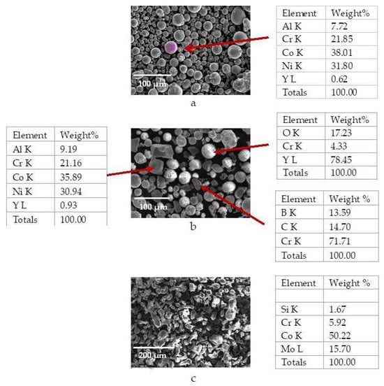
Figure 1.
Morphological characteristics of the as-received (a) CoNi alloy feedstock powder and corresponding EDS analysis, (b) CoNi cermet feedstock powder and corresponding EDS analysis, (c) CoMo alloy feedstock powder and corresponding EDS analysis.
The CoNi alloy powder particle shape is essentially spherical with two distinct size distributions one in the range of 4–5 μm and 20–25 μm, respectively (Figure 1a). EDS analysis confirmed a homogeneous powder consisting of Co, Ni, Cr, Al, and Y as expected. In contrast, the CoNi cermet powder comprises both spherical and angular grains mixed together (Figure 1b). The spherical porous particles are identified as Y2O3, while the angular particles, characterized by their rough surfaces, are associated with CoNiCrAlY. The dense particles with flat, glossy surfaces correspond to CrC and CrB2, based on EDS analysis. The third reference feedstock powder, CoMo alloy, consists of irregular droplet-shaped particles (Figure 1c). Its chemical composition is uniform throughout the grains, which contain Co, Mo, Cr, and Si.
For the development of CNT-reinforced coatings, all three feedstock powders shown in Table 1 were mixed with 5% wt. SWCNTs prior to deposition. Mixtures of reference materials with single-walled carbon nanotubes (SWCNTs) having a diameter of less than 2 nm (specifically, Tuball 99 ± 0.5% by OCSiAl) were utilized. Figure 2 presents scanning electron microscopy (SEM) micrographs along with energy-dispersive X-ray spectroscopy (EDS) chemical analysis of both the carbon nanotubes and the resulting mixtures. The objective was to create high-quality composite coating systems well adhered to the steel substrate to investigate their tribological behavior and wear resistance.
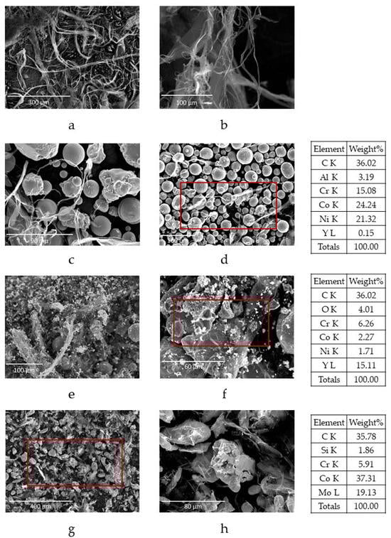
Figure 2.
Morphological characteristics of (a,b) SWCNT powder used in feedstock mixtures, (c,d) CoNi alloy with CNT mixture and respective EDS analysis of the area in the red frame, as well as (e,f) CoNi cermet with CNT mixture and respective EDS analysis of the area in the red frame, (g,h) CoMo alloy with CNT mixture and respective EDS analysis of the area in the red frame.
To prepare the MMC feedstock powders, a dry ball milling process was conducted using zirconia balls with a ball-to-powder mass ratio of 4:1. The milling was performed for 48 h at a speed of 90 rpm. Each reference powder, that is CoNi alloy, CoNi cermet, and CoMo alloy, was mixed with 5% by weight of single-walled carbon nanotubes in the form of clusters (Figure 2a,b) as revealed by their optical observation with scanning electron microscopy (SEM). Furthermore, EDS analysis of the mixtures demonstrated a sufficient distribution of CNT clusters of varying lengths and sizes among the matrix particles, as illustrated in Figure 2. This distribution is attributed to van der Waals and electrostatic forces [14]. Sandblasted plane carbon steel coupons, equivalent to SAE 9254, of 30 mm × 30 mm × 2 mm in dimension, were used as substrates for all coatings deposited and subsequently characterized.
2.2. Plasma Spray Deposition
The thermal spray method used to create the reference and the reinforced metal matrix composite coatings was atmospheric plasma spraying with an SG-100 spray gun (Praxair, Danbury, CT, USA). This process utilized a mixture of inert gases, primarily argon, with helium as a secondary gas. The flow rate for argon ranged from 40 to 50 slpm, while for helium, the flow rate was between 20 and 25 slpm. Coating deposition was performed using these inert gases, so that CNTs when plasma sprayed are less exposed to atmospheric oxygen in order to mitigate as much as possible potential oxidation and structural degradation at elevated temperatures, preserving their reinforcing effect and therefore promoting their interaction with the matrix [34]. During deposition, the possibility of some degree of carbon degradation cannot be ruled out. However, the high surface area-to-volume ratio of SWCNTs also allows for more effective load transfer when preserved.
The feedstock powders were delivered to the spray gun pneumatically, using argon as the carrier gas, with feed rate varying from 6.5 to 30 g/min. During the coating application, the distance from the spray gun to the substrate was maintained at 100 mm.
2.3. Characterization Techniques
The roughness parameter Ra was determined on each specimen using a TR-100 surface roughness tester (Time Group Inc., Beijing, China). The surface roughness parameter is based on standard roughness evaluation formula and is calculated by taking an average of ten measurements from various points on each specimen by Equation (1).
where lR is the calculation line and Z(x) the surface elevation.
The feedstock powders as well as the reference and reinforced MMC thermally sprayed coatings were investigated in terms of phase composition using a Siemens D500 (Cu, Ka) X-Ray Diffractometer (Bruker, Billerica, MA, USA). Furthermore, morphological and microstructural analysis of the surfaces and the cross section of coated specimens were performed by SEM combined with EDS analysis.
Microhardness evaluation was conducted on the cross sections of coatings using a Shimadzu HMV-2 tester (Shimadzu Corporation, Kyoto, Japan) operating with loads from 0.1 to 10 N, designed for high-accuracy measurements on cross-sectional microstructures with a load of 0.981 N (HV0.1). The average microhardness was determined as the mean value out of ten measurements taken across the coating, oriented perpendicularly to the interface between each coating and its substrate.
The coating-substrate bonding strength was evaluated using a pull-off Elcometer 110 Pneumatic Adhesion Tester (Elcometer Instruments Ltd., Manchester, UK) which functions with pressures up to 20 MPs. The results are expressed in MPa as the average of five measurements. Some variability in adhesion values was attributed to localized microstructural differences. Stereoscopic examination of the tested specimens was conducted to determine the failure mode of the coatings. The type of failure—either cohesive or adhesive—was identified by measuring the percentage of separation from the surface through image analysis.
Experiments were conducted using a standard pin-on-disc setup provided by CSEM equipment to investigate the wear behavior of the produced coating. Specifically, the wear behavior of the coatings was analyzed by calculating the specific wear rate, as outlined in Equation (2), and the friction coefficient, as presented in Equation (3). All calculations were performed in accordance with ASTM G99 standards by standard evaluation formulas.
where V is the volume loss in mm3; W is the applied load in N; and s is the sliding distance in m.
The rotational speed of the disk was set at 314 rpm, and the track diameter was 20 mm. The tests were carried out under unlubricated conditions at room temperature and roughly 65% humidity, with a normal applied load of 10 N for 5000 cycles. The counter body was a WC sphere of 6 mm in diameter. Subsequently, the wear tracks were analyzed using scanning electron microscopy, in order to determine wear mechanisms that occurred during friction tests.
3. Results and Discussion
3.1. Surface Morphology, Roughness and Phase Composition
The scanning electron micrographs reveal significant differences in the surface morphologies of the coatings, with (reinforced) and without (reference) carbon nanotubes (CNTs), indicating their impact on the structure and characteristics of the coatings. In any case, incorporation of CNTs is proved by EDS area analysis in all reinforced coatings (comparative EDS results are shown in Figure 3). The CoNi cermet coatings (Figure 3a,b) exhibit a relatively smooth surface morphology with well-defined melted regions (Area 1) and occasionally distributed residual crystallites (Area 2), representing partially unmelted particles. Incorporation of CNTs into these coatings (Figure 3c,d) introduces notable bridging (structures highlighted as area 3), enhancing cohesion between the melted and unmelted regions. These CNT networks provide the advantage of improving the mechanical properties of the coating, such as tensile strength and wear resistance, by acting as reinforcements while reducing voids. Similarly, the CoMo alloy coatings (Figure 3e,f) display a characteristic mix of melted areas and coarse crystallites. However, when CNTs are added (Figure 3g,h), the surface morphology changes, showcasing increased uniformity and CNT bridging that further strengthens the material. This bridging effect not only enhances cohesion but may also contribute to improved thermal and electrical conductivity, making these coatings suitable for high-performance applications. Lastly, the CoNi alloy top surface micrographs (Figure 3i,j) show a predominantly melted surface with minimal residual crystallites. Upon CNT inclusion (Figure 3k,l), there is a marked enhancement in the microstructural complexity, with the CNTs forming networks that promote structural stability and reduce potential defect sites. Comparatively, the addition of CNTs consistently results in coatings with improved homogeneity, structural integration, and enhanced properties. While the reference alloys and cermets during deposition have inherent differences in their thermal behavior and morphological and/or phase composition characteristics, the common effect of CNTs across all systems is to bridge gaps and improve interfacial bonding. CNT bridging plays a vital role in improving coating properties, such as cohesion which has also been reported in the case of CNT-reinforced plasma-sprayed alumina coating by Bakshi et al. in [35] and Mohanty et al. in [36]. This suggests that CNTs serve as a universal reinforcement material for plasma-sprayed coatings, effectively addressing challenges like porosity and weak interfaces. Thus, coatings with CNTs demonstrate superior mechanical and thermal performance compared to their non-CNT counterparts, highlighting their potential for advanced engineering applications in demanding environments [37,38,39].
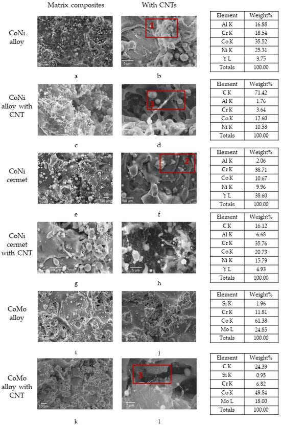
Figure 3.
Scanning electron micrographs showing the surface morphology of the coatings CoNi alloy (a,b), CoNi alloy with CNTs (c,d), CoNi cermet (e,f), CoNi cermet with CNTs (g,h), CoMo alloy (i,j), CoMo alloy with CNTs (k,l). [Area 1: melted regions, area 2: residual crystallites, area 3: CNT bridging].
The top surface of the as-deposited CoMo alloy as well as the CoMo alloy with CNT coatings (Figure 3e,f and Figure 3g,h, respectively) presented roughness values in the order of Ra = 3.22 ± 0.22 μm and Ra = 3.66 ± 0.22 μm, respectively, while the surface of CoNi cermet and CoNi cermet with CNT coatings (Figure 3a,b and Figure 3c,d, respectively) presented roughness values in the order of Ra = 2.53 ± 0.25 μm and Ra = 1.95 ± 0.25 μm, respectively. CoNi alloy and CoNi alloy with CNT presented mean roughness values in the order of Ra = 2.46 ± 0.20 μm and Ra = 2.05 ± 0.20 μm, respectively (Table 2). The introduction of CNTs in the feedstock powder has a minor impact on the as-deposited surface topography of the reinforced coatings. More specifically, the addition of CNTs in CoNi and CoMo metal matrices seems to have a very mild effect on surface roughness. Ra values fluctuations when comparing the reference with respective reinforced coatings are practically within measurement error with a slightly decreasing tendency, most probably because CNTs fill the voids that are often created during plasma spraying, thus reducing surface porosity and therefore roughness. The highest roughness value of 3.66 ± 0.22 μm is attributed to the presence of coarse crystallites within the CoMo alloy coating.
Table 2.
Characteristics of the investigated plasma-sprayed coatings.
In Figure 4, Figure 5 and Figure 6, the phase composition of the three different feedstock powders along with their respective reference and reinforced MMC using CNT coatings are shown. In all cases, most of the changes are attributed to the hot thermal spray process. Powder particles during their flight through the plasma flame are exposed to high temperature apart from the rapid solidification upon impact to the cold substrate. Therefore, some quantity of the deposited material is not fully crystalline; meanwhile, in certain cases, recrystallization leads to phases different than the ones of the original feedstock material.
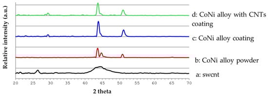
Figure 4.
X-Ray diffraction diagram showing the phase composition of (a) CNT powder, (b) feedstock powder Amperit 415.054, (c) CoNi alloy, and (d) respective CoNi alloy with CNT coating.
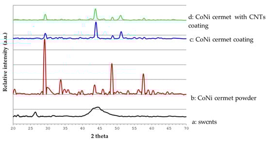
Figure 5.
X-Ray diffraction diagram showing the phase composition of (a) CNT raw powder, (b) feedstock powder Amperit 473.054, as well as respective (c) CoNi cermet and (d) CoNi cermet with CNT coatings.
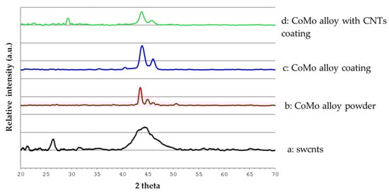
Figure 6.
X-Ray diffraction diagram showing the phase composition of (a) CNT raw powder, (b) feedstock powder Metco 66F-NS, as well as (c) CoMo alloy and (d) CoMo alloy with CNT coatings.
The crystalline phase composition of the as-deposited reinforced coatings is not significantly affected by the presence of carbon nanotubes (Figure 4a, Figure 5a and Figure 6a). On the one hand, nanotubes within the coatings are not detected as a separate phase probably due to their low concentration in the feedstock powder [40] and on the other hand, no phases containing carbon were identified in the XRD diagrams, confirming the SEM optical indication (Figure 3) that the majority of CNTs remain intact within the coating mass.
More specifically, the CoNi alloy feedstock powder (Figure 4b) consists of Co5.15Al4.85 (PDF standard peak#46-1012) and Cr2Ni3 (PDF standard peak#65-6291). After deposition as reference coating (Figure 4c), both phases’ main peaks are “combined” in a broader one. No phase changes are observed in the CNT-reinforced coating (Figure 4d).
Furthermore, the CoNi cermet multi-phased feedstock powder (Figure 5b) consists of Co5.15Al4.85 (PDF standard peak standard peak#46-1012) and Cr2Ni3 (PDF standard peak#65-6291) attributed to CoNiCrAlY, well crystallized Y2O3 (PDF standard peak#65-3178), and CrB2 (PDF standard peak#34-0369). It is obvious that in both the reference (Figure 5c) and CNT-reinforced (Figure 5d) coatings, the yttrium oxide crystallinity is lower due to the particles flight through the flame and solidification. The broadened CoNiCrAlY peak is present in Figure 5c,d just like in Figure 4c,d.
The third material investigated in this study, the CoMo alloy (Figure 6b), consists of Ni-Cr-Co-Mo (PDF standard peak#35-1489), Cr5Si3 (PDF standard peak#51-1375), and Co3Mo2Si (PDF standard peak#30-0449) in the form of commercial feedstock powder. In this case, main peak broadening is also observed after deposition no matter whether it is a reference (Figure 6c) or a CNT-reinforced (Figure 6d) coating.
3.2. Microstructural Characterization
Table 2 summarizes some of the investigated and evaluated plasma-sprayed coating properties, namely average coating thickness, roughness, adhesion strength, and microhardness.
The reference coatings (CoNi alloy, CoNi cermet, and CoMo alloy) as well as the respective CNT-reinforced ones are characterized by homogeneity and consistency in terms of thickness (Figure 7) in the range of 100–250 μm (Table 2) depending on the different metal matrix material. Scanning electron micrographs of cross-sectional plasma-sprayed reinforced coatings reveal distinct microstructural characteristics, highlighting the impact of carbon nanotube (CNT) incorporation on the coatings’ properties (Figure 7b,d,f,h,j,l). Dispersion of SWCNTs remains a challenge, primarily due to their strong van der Waals forces which may lead to bundling and agglomeration [41,42]. Several studies have reported similar observations, leading to non-uniform microstructures and impaired mechanical performance in CNT–metal composites [43,44]. These agglomerates not only reduce the effective surface area for load transfer but can also act as stress concentrators, negatively impacting local particle cohesion. Although a similar effect has been observed in the development of composite metal matrix coatings with the introduction of polymeric microcapsules in the range of microns containing liquid lubricants, their tribological performance was very satisfying.
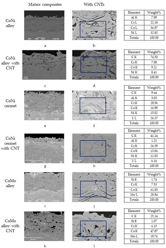
Figure 7.
Scanning electron micrographs showing microstructure of the coatings CoNi alloy and respective EDS analysis of the area in the blue frame (a,b), CoNi alloy with CNTs and respective EDS analysis of the area in the blue frame (c,d), CoNi cermet and respective EDS analysis of the area in the blue frame (e,f), CoNi cermet with CNTs and respective EDS analysis of the area in the blue frame (g,h), CoMo alloy and respective EDS analysis of the area in the blue frame (i,j), and CoMo alloy with CNTs and respective EDS analysis of the area in the blue frame (k,l).
SEM observation of the deposited coatings combined with EDS analysis (high concentration of C element in the corresponding cross sections) verified the presence of CNTs in the form of clusters. Their size and dispersion throughout the coating mass depends on the metal matrix selected. All deposited coatings exhibited the typical lamellar microstructure of plasma-sprayed coatings (Figure 7a,c,e,g,i,k).
The CoNi alloy (Figure 7a,b) exhibits a layered structure typical of plasma-sprayed coatings, with melted and partially melted regions. The layers are characterized by a combination of dense and porous areas, where the porosity arises due to incomplete melting or poor interlayer bonding. Upon the addition of CNTs (Figure 7c,d), the structure becomes more refined, with a noticeable reduction in porosity and enhanced interlayer cohesion. This improvement is likely due to the CNTs acting as fillers that bridge gaps between layers, contributing to better mechanical properties and reduced defect propagation under stress [45].
The CoNi cermet coatings (Figure 7e,f) display a composite structure with ceramic and metallic phases. The micrographs show a distinct separation between the phases, with ceramic particles embedded in a metallic matrix. However, without CNT bridging, the interfaces between the ceramic and metallic phases may appear inconsistent, leading to potential weaknesses under mechanical or thermal loads. The coating structure is interspersed with micrometer (10–20 μm) and submicrometer pores (<5 μm), concentrated in the upper layers (Figure 7e). No microcracks were observed within the coating or at the coating–substrate interface, as can be seen in Figure 7e and Figure 7f, respectively. The addition of CNTs (Figure 7g,h) results in a more homogeneous distribution of the ceramic particles and better integration within the metallic matrix. The CNTs likely enhance the wettability and bonding between phases, leading to improved structural integrity and potentially better resistance to wear and thermal cycling [46]. The CoNi cermet coating with CNTs shows a well-bonded interface between the coating and the substrate with no interfacial porosity.
In the case of CoMo alloy coatings (Figure 7i,j), the microstructure is primarily metallic, with regions of melted and resolidified material forming dense layers interspersed with small voids. The voids, a common feature in plasma-sprayed coatings, reduce the mechanical strength and durability of the coating. Small-sized pores (5–10 mm) appeared mainly near the interface between the coating and the substrate. Microcracks observed by SEM investigation were not detrimental to the quality of the coatings (max. length of <10 μm). The inclusion of CNTs (Figure 7k,l) leads to a medium-quality microstructure, with large bundles of CNTs enclosed and randomly dispersed along the coating.
The above mentioned results highlight the universal benefits of the addition of CNTs which ensures better heat dissipation and lower plasma power, and lowers the flame temperature, therefore lowering the coating temperature during deposition and finally hindering the formation of porosity. In all cases, the CNT-reinforced coatings exhibit reduced porosity, better phase integration, and enhanced interlayer bonding. These improvements stem from the unique properties of CNTs, including their high thermal and electrical conductivity, mechanical strength, and ability to form networks that distribute stresses more evenly. While the metal matrix materials—CoNi alloy, CoNi cermet, and CoMo alloy—exhibit inherent differences in microstructure due to their chemical composition and particle shape and size, the addition of CNTs consistently enhances their overall performance.
3.3. Adhesion Strength Test
The adhesion test revealed that the CoMo alloy coating, which is a single phase coating containing molybdenum (Mo) and high cobalt (Co) weight percent, presented bonding strength in the order of 15.7 MPa (Table 2 and Figure 8) with 25% adhesive failure at the substrate–coating interface (Figure 9e). Addition of CNTs in CoMo alloy coating (Figure 9f) resulted in larger decohesion area (~49% cohesive failure inside the coating) and slightly higher average bonding strength in the order of 17.8 MPa.
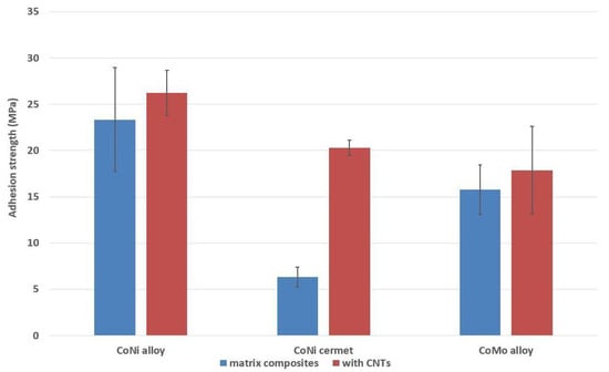
Figure 8.
Comparison of mean adhesion strength for reference and respective reinforced coatings.
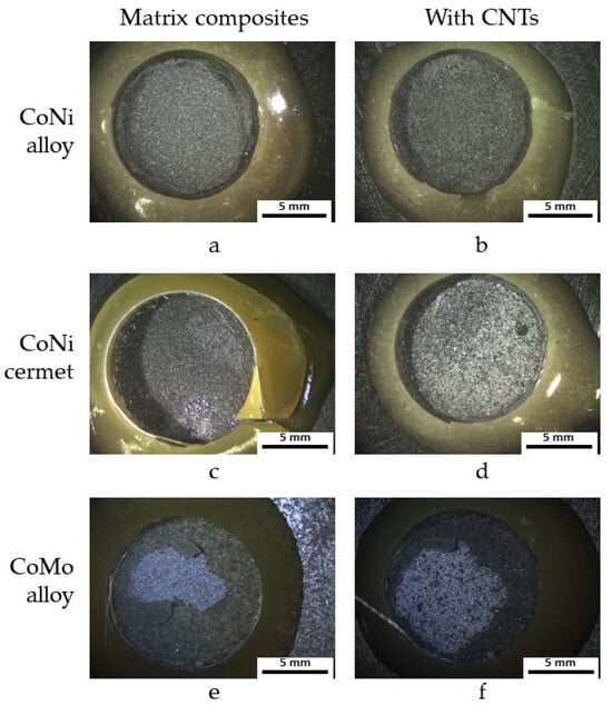
Figure 9.
Indicative fracture surface after adhesion test: (a,b) CoNi alloy coating and CoNi alloy coating with CNTs, (c,d) CoNi cermet coating and CoNi cermet coating with CNTs, (e,f) CoMo alloy coating and CoMo alloy coating with CNTs.
On the other hand, in relation to the multi-phased CoNi cermet and CoNi cermet with CNT coatings that contain lesser cobalt (Co) with a simultaneous absence of molybdenum (Mo) and presence of nickel (Ni) and chromium (Cr) as compared to the above-mentioned coatings, although the average measured bonding strength (Table 2, Figure 8) of the reference coating was significantly lower, in the order of 6.3 MPa, cohesive failure was uniform (Figure 9c). This result can most probably be attributed to the different chemical composition, in combination with the microstructural homogeneity of these coatings. It is worth mentioning that improved dispersion of CNTs in the CoNi cermet coating seems to positively influence their adhesive behavior confirming CNT bridging. The CoNi cermet coating with CNTs demonstrated superior adhesion performance compared to the corresponding metal matrix coating benefiting from improved cohesion between the ceramic and metallic phases due to CNT reinforcement and therefore bridging. As can be seen in Table 2 and Figure 8 and Figure 9d, the adhesion strength of CoNi cermet was increased by 33%.
Additionally, the CoNi alloy-based coating exhibits the highest adhesion strength of all reference coatings, in the order of 23.3 MPa (Table 2 and Figure 8) presenting uniform cohesive failure (Figure 9a). In the CoNi alloy reinforced coating, the CNTs also contributed to a significant lack of impurities and better interfacial bonding, resulting in increased adhesion strength, in the order of 28.7 MPa (23% increase compared to reference coating) (Table 2, Figure 8 and Figure 9b).
3.4. Microhardness
The average Vickers microhardness value of the obtained reinforced coatings (Figure 10 and Table 2) was significantly lower in all cases, compared to the corresponding values of the reference coatings. While the presence of CNTs within the coating has been shown to promote the bridging mechanism between splats, some researchers suggest that the decarburization phenomena of CNTs occurring during deposition might hinder cohesion locally between the feedstock particles, producing interlamellar defects and increased micro- and nano-porosity in the coating mass [47]. In addition, as CNTs are not as hard as ceramic or metal matrix materials, when added, they occupy regions creating clusters within the coating that might otherwise be filled by harder phases, effectively reducing the overall hardness of the composite coating despite its structural refinement. This fact is also verified by the increased microhardness standard deviation values of the reinforced coatings (Table 2). Consequently, a decrease in microhardness values could be also correlated with the simultaneous effect of both factors. Moreover, high inclusion of CNTs in the composites may form clustering, which reduces the hardness of the coating. The softer CNTs contribute more to toughness and ductility rather than to microhardness [37].
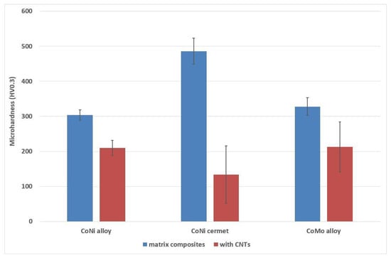
Figure 10.
Comparative diagram of microhardness for reference and respective reinforced coatings.
3.5. Friction and Wear Behavior
Figure 11 shows a comparative bar diagram of the coefficient of friction for all types of coatings during pin-on-disc measurements. Corresponding COF profiles versus number of cycles are also presented giving a clearer view of the evolution of tribological behavior. At the beginning of the wear process, all coatings undergo a “saturation” stage, during which the contact surfaces adapt to each other, often resulting in an unstable COF increase due to asperity interaction, material transfer, or debris accumulation. As the wear process continues, the coatings enter a “transition” stage, in which the value of the friction coefficient increases slightly. Finally, the wear process becomes stable, and the friction coefficients tend to stabilize without significant variation. CoMo alloy, CoMo alloy with CNTs, CoNi alloy, and CoNi alloy with CNT coatings present an interesting behavior, with sudden changes in the coefficient of friction at the point of approximately 2500 cycles, whereas CoNi cermet and CoNi cermet with CNTs show smoothly varying respective curves.
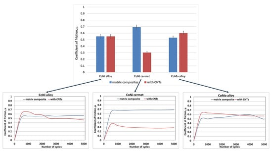
Figure 11.
Comparative bar diagram and profiles of friction coefficient for reference and respective reinforced coatings.
For the CoNi alloy, the addition of CNTs results in a modest but important improvement: while the average COF remains roughly the same, the sliding profile becomes more stable, and peak fluctuations are reduced (Figure 11—profile diagram). This can be attributed to the intrinsic lubricating nature of CNTs, which tend to form a thin protective film on the wear surface. This film can act as a solid lubricant by reducing metal–metal contact, smoothing out surface asperities, and trapping wear debris. The relatively homogeneous metallic matrix of CoNi provides a compatible interface for CNTs, enabling moderate dispersion and integration. This synergy limits abrasive wear and stabilizes friction, although the impact on mean COF values is less pronounced than in other systems.
Similarly, the addition of CNTs in the CoNi cermet coating seems to have a significantly positive effect on the friction coefficient. Here, the incorporation of CNTs substantially reduces the COF—from ~0.70 to ~0.35—making it the most friction-optimized coating in this study. The ceramic particles in the cermet matrix, while enhancing wear resistance, can also increase surface hardness and brittleness, often leading to microfracturing under stress. CNTs act synergistically by bridging microcracks, improving phase bonding, and filling intersplat voids, which minimizes abrasive interactions. Additionally, dispersed CNTs reinforce the matrix without forming stress concentrators, while also contributing to a lubricious tribofilm formation during sliding. The overall effect is a more resilient and toughened surface with low shear resistance and reduced material loss—ideal for high-performance wear applications.
Interestingly, the CoMo alloy exhibits a contrasting behavior, where the incorporation of CNTs increases its friction coefficient. The friction coefficient increases during the stage of 0–3000 cycles to approximately 0.60 and then stabilizes at around 0.64 creating a plateau. CoMo alloy with CNTs presented the opposite behavior becoming stable after 2500 cycles obtaining a decreased average value of approximately 0.58 attributed to the CNT addition. This unexpected result may stem from several factors. First, the interaction between CNTs and the CoMo matrix might lead to poor dispersion or agglomeration, creating asperities that increase surface roughness. Second, the lubricating mechanisms of CNTs could be less effective in the CoMo matrix due to differences in adhesion or interfacial compatibility. Also, the inherent properties of CoMo, such as its natural lubricity, which derive from molybdenum and chromium phases might be disrupted by the addition of CNTs, which could alter the microstructure or surface characteristics. In addition, CNT degradation or decarburization in this system might weaken their structural integrity. Moreover, poor microstructure, consisting of large bundles of CNTs enclosed and randomly dispersed along the coating, also led to poor evolution of friction. As a result, stress concentrations form around CNT bundles accelerating localized wear. The absence of effective CNT–matrix bonding also impairs load transfer and encourages fatigue-driven material loss, disrupting otherwise beneficial friction-lowering mechanisms.
In Figure 12, the specific wear rates of the coatings are shown. In the case of CoNi alloy, wear rate was reduced significantly by the addition of CNTs, in the range of 80%, from 76.96 × 10⁻⁵ mm3/Nm to 12.77 × 10⁻⁵ mm3/Nm, while CoNi cermet coatings (with and without CNTs), exhibited the lowest wear rate, taking values of 3.89 × 10⁻⁵ mm3/Nm and 18.56 × 10⁻⁵ mm3/Nm, respectively, also resulting in almost an 80% decrease. In contrast, CoMo alloy coating exhibited the opposite behavior. The addition of CNTs led to an increase in wear rate of about 78%. This is probably due to cohesion deterioration by the inhomogeneous nanotubes’ distribution within the coating mass.
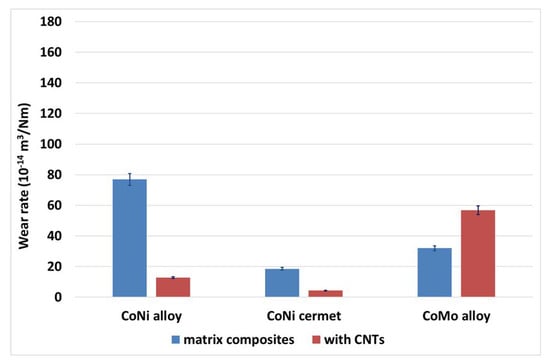
Figure 12.
Wear rate bar diagram for reference and respective reinforced coatings.
SEM images of wear tracks provide greater understanding into wear behavior. Wear mechanism analysis indicates that the CoNi alloy without CNTs exhibits a wear mechanism dominated by severe abrasive wear, as evidenced by the presence of deep grooves and plowing marks (Figure 13(A3)). These features suggest that hard asperities or debris particles act as third-body abrasives, leading to material removal through micro-cutting and plastic deformation (Figure 13(A2)). Additionally, the worn surface shows delamination, indicative of localized subsurface cracking and subsequent material detachment, a characteristic of fatigue wear. The extent of these wear features suggests that the CoNi alloy alone has a moderate resistance to wear but is still prone to significant material loss under prolonged loading conditions, as confirmed by wear rate too (Figure 12). In contrast, the CoNi alloy reinforced with CNTs (Figure 13(B1–B3)) exhibits a distinctly different wear mechanism. The worn surfaces display shallower grooves and a more uniform texture (Figure 13(B1–B2)), suggesting that the incorporation of CNTs enhances wear resistance. The predominant mechanism appears to be mild abrasive and adhesive wear, where the transfer film formation due to CNTs helps in reducing wear loss. The presence of CNTs likely acts as a solid lubricant, reducing friction and mitigating severe material loss (Figure 12). Furthermore, the absence of extensive delamination features in the CNT-reinforced coating suggests improved toughness and load-bearing capacity. This indicates that CNTs contribute to strengthening the CoNi matrix, thereby reducing subsurface cracking and fatigue-related wear.
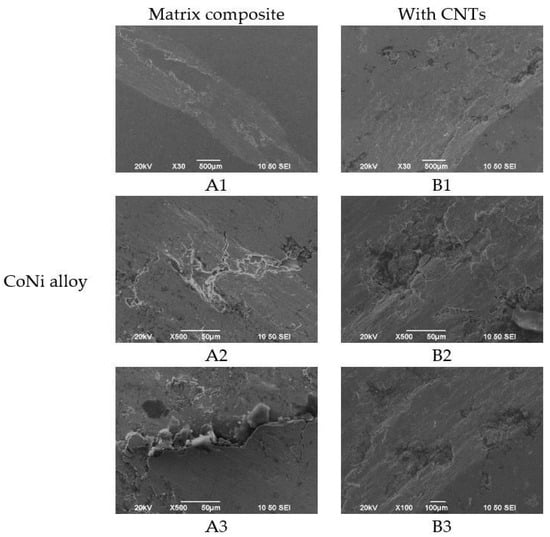
Figure 13.
Scanning electron micrographs of the CoNi alloy coating’s wear track surface (A1–A3) and of CNT reinforced CoNi alloy coating’s wear track surface (B1–B3).
The CoNi cermet without CNTs (Figure 14(A1–A5)) exhibits a wear mechanism primarily governed by abrasive and brittle fracture wear. The worn surface features deep grooves and crack formations (Figure 14(A2)), indicative of the brittle nature of the cermet material under mechanical stress. Additionally, the detachment of hard particles suggests a micro-fracturing process, where localized stress concentrations lead to particle pullout (Figure 14(A3)) and subsequent three-body abrasive wear. The presence of microcracks and surface spalling further confirms that brittle fracture is a significant contributor to material degradation, which can accelerate wear failure over time.
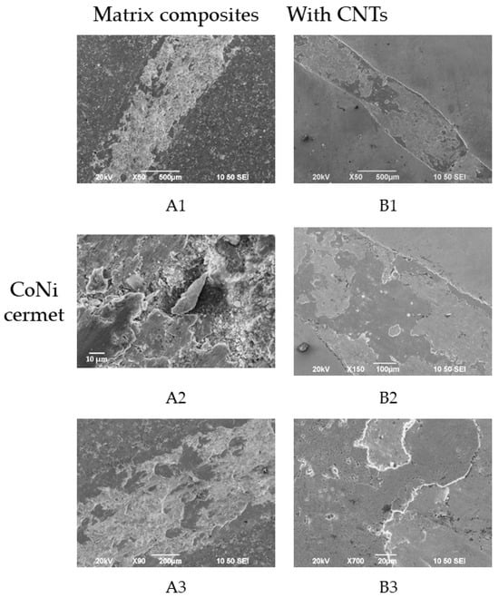
Figure 14.
Scanning electron micrographs of the CoNi cermet coating’s wear track surface (A1–A3) and of the CNT reinforced CoNi cermet coating’s wear track surface (B1–B3).
On the other hand, the CoNi cermet reinforced with CNTs (Figure 14(B1–B3)) exhibits a more wear-resistant surface characterized by shallower grooves and reduced cracking (Figure 14(B1,B2)). The wear mechanism shifts towards mild abrasive and adhesive wear, as indicated by smoother worn regions (Figure 14(B3)) and a more homogeneous material loss pattern (Figure 12). The incorporation of CNTs appears to enhance the toughness of the cermet matrix, reducing the likelihood of brittle fracture and promoting plastic deformation instead. The CNTs are likely to contribute to crack deflection and energy dissipation, preventing catastrophic failure. Additionally, the presence of a tribolayer suggests that CNTs aid in forming a protective film that reduces direct asperity contact and minimizes material removal.
Wear tracks of the CoMo alloy (Figure 15(A1–A5)) and CoMo alloy with CNTs (Figure 15(B1–B5)) are wider compared to the CoNi cermet and CoNi alloy coatings’ track (in the order of 1 mm) and present marks of ploughing (Figure 15(A1,B1,B2,A4) and (B4)). Severe damage, and therefore great mass loss, was observed in both coatings. A thorough examination of the surface revealed the existence of a significant number of cracks (Figure 15(A2)) that were generated most probably due to surface fatigue. In the case of contact in the running-in state, fatigue fracture is assumed to be generated after repeated friction cycles. The material removal is governed by deformation and fracture in the contact region, indicating fracture due to fatigue. Such deformation and fracture (Figure 15(B3)) are generated by mechanically induced strains and residual tensile stresses on the coating. During the running-in state, there is high stress concentration around specific points beyond the coatings’ elastic limit leading in permanent deformation (plastic strain) due to repeated friction under elastic or elastoplastic contact. Exceeding a certain number of cycles, crack formation is also observed. The process of crack initiation and growth in this context is characteristic of fatigue fracture, a mechanism influenced by the microstructural heterogeneity of the material [48]. Scientific teams studying ceramic coatings subjected to abrasive wear have identified fatigue cracking as a secondary wear mechanism. For example, Hyo-Sok Ahn et al. observed delamination of a thin Cr2O3 coating layer due to fatigue cracking [49], while Pantelis et al. identified a combined polishing/abrasion/fatigue wear mechanism of Al2O3 plasma-sprayed coating [50]. Furthermore, in the case of the CoMo alloy with CNTs, the increased wear rate (Figure 12) reflecting increased material removal is confirmed by the abrasive marks on its worn surface (Figure 15(B3)) alongside extensive areas of exfoliated splats. Notably, at the conclusion of the pin-on-disc test, the substrate was exposed in certain regions (Figure 15(B1)), a finding supported by the elevated Fe content detected in the wear track (Figure 15(B1), compare points 1 and 2 in the EDS analysis). The reduction in wear resistance of these coatings can be most probably attributed to worsening microstructural characteristics promoting coating’s brittleness, also reflecting their adhesion behavior as described above. They exhibited a combined adhesive and cohesive failure, which implies less homogeneity as compared to the CoNi cermet and CoNi alloy (both with and without CNT coatings).
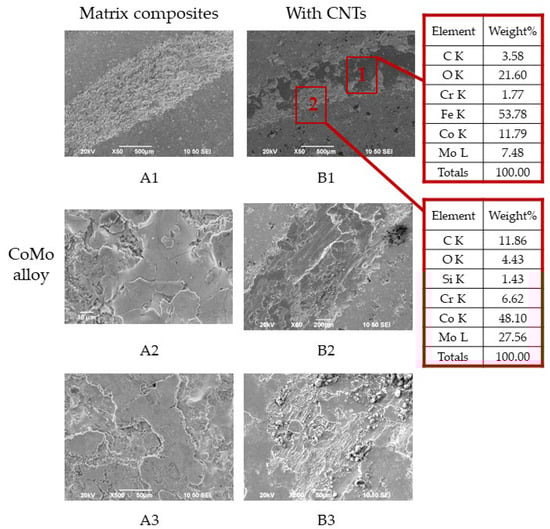
Figure 15.
Scanning electron micrographs of the CoMo alloy coating’s wear track surface (A1–A3) and of the CNT reinforced CoMo alloy coating’s wear track surface (B1–B3) with EDS analysis in different areas (area 1, area 2).
4. Conclusions
This paper is an exceptional starting point for further research in the field of the application of nanotubes acting as lubricants inside metal matrix, and in particular Co-based thermal spray coatings.
In summary, the current investigation highlights the pivotal role of single-walled carbon nanotubes (SWCNTs) as reinforcements in Co-based atmospheric plasma-sprayed coatings, yielding significant advancements in tribological performance.
The incorporation of SWCNTs into CoNi alloy and CoNi cermet matrices enhanced wear resistance, reduced the coefficient of friction, and improved adhesion strength, with CoNi cermet demonstrating particularly remarkable stability and cohesion. More precisely, among all examined systems, the CoNi cermet coating reinforced with CNTs exhibited the most remarkable enhancement: the coefficient of friction (COF) decreased from approximately 0.70 to 0.35, and the specific wear rate was reduced by nearly 80%. Moreover, the adhesion strength of this coating increased from 6.3 MPa to 20.29 MPa, reflecting a significant improvement due to enhanced cohesion and interfacial bonding facilitated by CNT bridging. The CoNi alloy-based coating also benefited from CNT addition, with adhesion strength increasing from 23.35 MPa to 28.70 MPa and wear rate dropping from 76.96 × 10⁻⁵ mm3/N·m to 12.77 × 10⁻⁵ mm3/N·m. These improvements confirm the role of CNTs as effective solid lubricants and reinforcing agents when properly dispersed within compatible matrices. In contrast, the CoMo alloy coatings demonstrated inconsistent tribological improvements. While the CNT addition slightly reduced COF in the steady-state regime (from ~0.64 to ~0.58), the wear rate increased, and local delamination and substrate exposure were observed. This behavior is attributed to poor CNT dispersion, clustering, and weak matrix compatibility in the CoMo system, highlighting the critical influence of matrix–CNT interaction on coating performance.
This study also revealed variations in effectiveness across different matrices, underscoring the importance of uniform CNT dispersion and matrix compatibility. While the CNT-reinforced coatings displayed notable bridging phenomena and enhanced structural integrity, some challenges, such as increased wear rates in CoMo alloys due to poor CNT distribution, emphasize the need for optimized processing techniques. These findings contribute to the growing body of knowledge supporting CNTs’ utility in advanced self-lubricating systems and their potential to address challenges in high-performance applications.
Apart from deviations observed in the CoMo alloy coatings, where poor CNT dispersion led to increased wear, the obtained results largely confirmed our initial expectations regarding the beneficial effects of CNT reinforcement—particularly in the CoNi cermet system. Future research should explore scalable dispersion techniques, alternative matrix combinations, and cost-performance optimization to further unlock the potential of CNT-based coatings for demanding tribological systems. Furthermore, investigations should include the techno-economic data of CNT-reinforced metal matrix coatings, considering raw material costs, processing complexity, equipment wear, environmental considerations, etc. Exploring alternative CNT sources or hybrid reinforcements (e.g., mixing SCNTs with MWCNTs, graphene, or ceramic nanoparticles) may further enhance performance, making such coatings competitive for broader commercial adoption.
Author Contributions
Conceptualization, I.G. and C.I.S.; methodology, I.G. and C.I.S.; validation, D.G. and D.A.; investigation, D.G., D.A., C.I.S., and I.G.; resources, I.G., D.A., and C.I.S.; data curation, I.G. and C.I.S.; writing—original draft preparation, I.G., D.G., D.A., and C.I.S.; writing—review and editing, I.G. and C.I.S.; visualization, I.G. and C.I.S.; supervision, I.G.; project administration, I.G. and C.I.S.; funding acquisition, D.A. and C.I.S. All authors have read and agreed to the published version of the manuscript.
Funding
This research has been co-financed by the European Regional Development Fund of the European Union and Greek National funds through the Operational Program “Competitiveness, Entrepreneurship and Innovation” under the call RESEARCH-CREATE-INNOVATE (project code: T2EDK-01883).
Data Availability Statement
The datasets generated for this study are available upon request to the corresponding author.
Acknowledgments
The authors would like to gratefully acknowledge P. Sarafoglou for her contribution to conceptualization, proposal preparation, and submission for funding of the T2EDK-01883 project. This article is a revised and expanded version of a paper entitled “Investigating the Effect of Solid Lubricants Addition on Friction and Wear Behaviour of Thermally Sprayed Coatings”, which was presented at the International Thermal Spray Conference ITSC2023 in Quebec Canada.
Conflicts of Interest
Authors Ilias Georgiopoulos, Dimitra Giasafaki and Dia Andreouli are employed by the company MIRTEC S.A. Author Chara I. Sarafoglou is working in the National Technical University of Athens (NTUA). All authors declare that the research was conducted in the absence of any commercial or financial relationships that could be construed as a potential conflict of interest.
References
- Tahir, N.A.M.; Abdollah, M.F.B.; Tamaldin, N.; Amiruddin, H.; Zin, M.R.B.M. A Brief Review on the Wear Mechanisms and Interfaces of Carbon Based Materials. Compos. Interfaces 2017, 25, 491–513. [Google Scholar] [CrossRef]
- Singh, S.; Berndt, C.C.; Singh Raman, R.K.; Singh, H.; Ang, A.S.M. Applications and Developments of Thermal Spray, Coatings for the Iron and Steel Industry. Materials 2023, 16, 516. [Google Scholar] [CrossRef]
- Joshi, S.; Nylen, P. Advanced Coatings by Thermal Spray Processes. Technologies 2019, 7, 79. [Google Scholar] [CrossRef]
- Farooq, S.A.; Raina, A.; Mohan, S.; Singh, R.A.; Jayalakshmi, S.; Haq, M.I.U. Nanostructured Coatings: Review on Processing Techniques, Corrosion Behaviour and Tribological Performance. Nanomaterials 2022, 12, 1323. [Google Scholar] [CrossRef] [PubMed]
- Shah, R.; Chen, R.; Woydt, M. The Effects of Energy Efficiency and Resource Consumption on Environmental Sustainability. Lubricants 2021, 9, 117. [Google Scholar] [CrossRef]
- Muratore, C.; Voevodin, A. Chameleon Coatings: Adaptive Surfaces to Reduce Friction and Wear in Extreme Environments. Annu. Rev. Mater. Sci. 2009, 39, 297–324. [Google Scholar] [CrossRef]
- Kiape, S.; Glava, M.; Georgatis, E.; Kamnis, S.; Matikas, T.E.; Karantzalis, A.E. CoCrFeMnNi0.8V/Cr3C2-Ni20Cr High-Entropy Alloy Composite Thermal Spray Coating: Comparison with Monolithic CoCrFeMnNi0.8V and Cr3C2-Ni20Cr Coatings. Coatings 2024, 14, 402. [Google Scholar] [CrossRef]
- Venturi, F.; Kamnis, S.; Hussain, T. Internal Diameter HVOAF Thermal Spray of Carbon Nanotubes Reinforced WC-Co Composite Coatings. Mater. Des. 2021, 202, 109566. [Google Scholar] [CrossRef]
- Espallargas, N.; Armada, S. A New Type of Self-Lubricated Thermal Spray Coatings: Liquid Lubricants Embedded in a Metal Matrix. J. Therm. Spray Technol. 2015, 24, 222–234. [Google Scholar] [CrossRef]
- Reinert, L.; Varenberg, M.; Mücklich, F.; Suárez, S. Dry Friction and Wear of Self-Lubricating Carbon-Nanotube-Containing Surfaces. Wear 2018, 406–407, 33–42. [Google Scholar] [CrossRef]
- Cornelio, J.; Cuervo, P.; Hoyos-Palacio, L.; Lara-Romero, J.; Toro, A. Tribological Properties of Carbon Nanotubes as Lubricant Additive in Oil and Water for a Wheel-Rail System. J. Mater. Res. Technol. 2016, 5, 68–76. [Google Scholar] [CrossRef]
- Bukvi´c, M.; Gajevi´c, S.; Skuli´c, A.; Savi´c, S.; Ašonja, A.; Stojanovi´c, B. Tribological Application of Nanocomposite Additives in Industrial Oils. Lubricants 2024, 12, 6. [Google Scholar] [CrossRef]
- Holmberg, K.; Erdemir, A. Influence of Tribology on Global Energy Consumption, Costs and Emissions. Friction 2017, 5, 263–284. [Google Scholar] [CrossRef]
- Sarafoglou, C.I.; Skaltsas, D.; Tsiourva, D.; Zotiadis, C.; Korres, D.M.; Ioannou, P.; Andreouli, D.; Papadopoulos, C.I.; Vouyiouka, S.; Georgiopoulos, I. Encapsulated Liquid Lubricants Incorporated in Metal Matrix Thermal Spraying Coatings. J. Therm. Spray Technol. 2024, 33, 786–805. [Google Scholar] [CrossRef]
- Moghadam, A.D.; Omrani, E.; Menezes, P.L.; Rohatgi, P.K. Mechanical and tribological properties of self-lubricating metal matrix nanocomposites reinforced by carbon nanotubes (CNTs) and graphene—A review. Compos. Part B Eng. 2015, 77, 402–420. [Google Scholar] [CrossRef]
- Patrikalos, J.; Ioannou, P.; Andreouli, D.; Georgiopoulos, I.; Skaltsas, D.; Papadopoulos, C.; Sarafoglou, C.I. Investigating the Effect of Solid Lubricants Addition on Friction and Wear Behaviour of Thermally Sprayed Coatings. In Thermal Spray 2023, Proceedings of the International Thermal Spray Conference, no. itsc2023p0392, Québec City, QC, Canada, 22–25 May 2023; ASM International: Almere, The Netherlands, 2023; pp. 392–399. [Google Scholar] [CrossRef]
- Moghadam, A.D.; Schultz, B.F.; Ferguson, J.B.; Omrani, E.; Rohatgi, P.; Gupta, N. Functional Metal Matrix Composites: Self-Lubricating, Self-Healing, and Nanocomposites-an Outlook. JOM 2014, 66, 872–881. [Google Scholar] [CrossRef]
- Venkatachalapathy, V.; Katiyar, N.K.; Matthews, A.; Endrino, J.L.; Goel, S. A Guiding Framework for Process [41] Parameter Optimisation of Thermal Spraying. Coatings 2023, 13, 713. [Google Scholar] [CrossRef]
- Kaewsai, D.; Watcharapasorn, A.; Singjai, P.; Wirojanupatump, S.; Niranatlumpong, P.; Jiansirisomboon, S. Thermal Sprayed Stainless Steel/Carbon Nanotube Composite Coatings. Surf. Coat. Technol. 2010, 205, 2104–2112. [Google Scholar] [CrossRef]
- Singla, M.K.; Singh, H.; Chawla, V. Thermal Sprayed CNT Reinforced Nanocomposite Coatings—A Review. J. Miner. Mater. Charact. Eng. 2011, 10, 717–726. [Google Scholar] [CrossRef]
- Kravchenko, I.; Kuznetsov, Y.; Velichko, J.; Yarina, S.; Dobychin, A.; Spasić, D.; Kalashnikova, L. Model for Evaluating the Plasma Coating Method. Adv. Eng. Lett. 2023, 2, 21–27. [Google Scholar] [CrossRef]
- Lu, X.; Bhusal, S.; He, G.; Zhao, D.; Zhang, C.; Agarwal, A.; Chen, Y. Efficacy of Graphene Nanoplatelets on Splat Morphology and Microstructure of Plasma Sprayed Alumina Coatings. Surf. Coat. Technol. 2019, 366, 54–61. [Google Scholar] [CrossRef]
- He, P.; Ma, G.; Wang, H.; Yong, Q.; Chen, S. Microstructure and mechanical properties of a novel plasma-spray TiO2 coating reinforced by CNTs. Ceram. Int. 2016, 42, 13319–13325. [Google Scholar] [CrossRef]
- Pérez-Bustamante, R.; Pérez-Bustamante, F.; Estrada-Guel, I.; Licea-Jiménez, L.; Miki-Yoshida, M.; Martínez-Sánchez, R. Effect of Milling Time and CNT Concentration on Hardness of CNT/Al2024 Composites Produced by Mechanical Alloying. Mater. Charact. 2013, 75, 13–19. [Google Scholar] [CrossRef]
- Jagadeeshanayaka, N.; Awasthi, S.; Jambagi, S.C.; Srivastava, C. Bioactive Surface Modifications through Thermally Sprayed Hydroxyapatite Composite Coatings: A Review of Selective Reinforcements. Biomater. Sci. 2022, 10, 2484–2523. [Google Scholar] [CrossRef]
- Kumar, S.; Bhatia, R.; Singh, H.; Virdi, R.L. Microstructural and Mechanical Properties of CNT-Reinforced ZrO2-Y2O3 Coated Boiler Tube Steel T-91. J. Electrochem. Sci. Eng. 2022, 12, 877–888. [Google Scholar] [CrossRef]
- Feijoo, I.; Pena, G.; Cristóbal, M.; Cabeza, M.; Rey, P. Effect of Carbon Nanotube Content and Mechanical Milling Conditions on the Manufacture of AA7075/MWCNT Composites. Metals 2022, 12, 1020. [Google Scholar] [CrossRef]
- Srinivasan, R.; Kamaraj, M.; Rajeev, D.; Ravi, S.; Senthilkumar, N. Plasma Spray Coating of Aluminum–Silicon-MWCNT Blends on Titanium Grade 5 Alloy Substrate for Enhanced Wear and Corrosion Resistance. Silicon 2022, 14, 8629–8641. [Google Scholar] [CrossRef]
- Bai, Y.; Zhang, R.; Zhu, X.Y.Z.; Xie, H.; Shen, B.; Cai, D.; Liu, B.; Zhang, C.; Jia, Z.; Zhang, S.; et al. Carbon nanotube bundles with tensile strength over 80 GPa. Nat. Nanotechnol. 2018, 13, 589–595. [Google Scholar] [CrossRef]
- Goh, C.S.; Wei, J.; Lee, L.C.; Gupta, M. Development of novel carbon nanotube reinforced magnesium nanocomposites using the powder metallurgy technique. Nanotechnology 2006, 17, 7–12. [Google Scholar] [CrossRef]
- Chen, X.; Liu, K.; Peng, S.; Zhang, L.; He, S.; Gorbatov, I.O.; Qu, X. Enhanced mechanical properties of the surface-modified CNTs reinforced 2195 aluminum-based composite. Mater. Sci. Eng. A 2025, 922, 147623. [Google Scholar] [CrossRef]
- Yuuki, J.; Kwon, H.; Kawasaki, A.; Magario, A.; Noguchi, T.; Beppu, J.; Seki, M. Fabrication of Carbon Nanotube Reinforced Aluminum Composite by Powder Extrusion Process. Mater. Sci. Forum. 2007, 534–536, 889–892. [Google Scholar] [CrossRef]
- Ujah, C.O.; Kallon, D.V.V.; Aigbodion, V.S. Tribological Properties of CNTs-Reinforced Nano Composite Materials. Lubricants 2023, 11, 95. [Google Scholar] [CrossRef]
- Terrones, M.; Grobert, N.; Olivares, J.; Zhang, J.P.; Terrones, H.; Kordatos, K.; Hsu, W.K.; Hare, J.P.; Townsend, P.D.; Prassides, K.; et al. Controlled production of aligned-nanotube bundles. Nature 2002, 388, 52–55. [Google Scholar]
- Bakshi, S.R.; Keshri, A.K.; Agarwal, A. A comparison of mechanical and wear properties of plasma sprayed carbon nanotube reinforced aluminum composites at nano and macro scale. Mater. Sci. Eng. A 2011, 528, 3375–3384. [Google Scholar] [CrossRef]
- Mohanty, D.; Kar, S.; Paul, S.; Bandyopadhyay, P.P. Carbon nanotube reinforced HVOF sprayed WC-Co coating. Mater. Des. 2018, 156, 340–350. [Google Scholar] [CrossRef]
- Mukherjee, B.; Rahman, O.A.; Islam, A.; Sribalaji, M.; Keshri, A.K. Plasma sprayed carbon nanotube and graphene nanoplatelets reinforced alumina hybrid composite coating with outstanding toughness. J. Alloys Compd. 2017, 727, 658–670. [Google Scholar] [CrossRef]
- Goyal, R.; Sidhu, B.S.; Chawla, V. Characterization of plasma-sprayed carbon nanotube (CNT)-reinforced alumina coatings on ASME-SA213-T11 boiler tube steel. Int. J. Adv. Manuf. Technol. 2017, 92, 3225–3235. [Google Scholar] [CrossRef]
- Goyal, K.; Singh, H.; Bhatia, R. Behaviour of carbon nanotubes-Cr2O3 thermal barrier coatings in actual boiler. Surf. Eng. 2020, 36, 124–134. [Google Scholar] [CrossRef]
- Wang, L.; Zhang, Z.; Luo, Y.; Xiao, Y.; Tan, F.; Liu, K. Understanding the Influencing Mechanism of CNTs on the Microstructures and Wear Characterization of Semi-Solid Stir Casting Al-Cu-Mg-Si Alloys. Metals 2022, 12, 2171. [Google Scholar] [CrossRef]
- Vaisman, L.; Wagner, H.D.; Marom, G. The role of surfactants in dispersion of carbon nanotubes. Adv. Colloid Interface Sci. 2006, 128, 37–46. [Google Scholar] [CrossRef]
- Bakshi, S.R.; Lahiri, D.; Agarwal, A. Carbon nanotube reinforced metal matrix composites—A review. Int. Mater. Rev. 2010, 55, 41–64. [Google Scholar] [CrossRef]
- Esawi, A.M.K.; Morsi, K. Dispersion of carbon nanotubes (CNTs) in aluminum powder. Compos. Part A Appl. Sci. Manuf. 2007, 38, 646–650. [Google Scholar] [CrossRef]
- Rashad, M.; Pan, F.; Yu, Z.; Asif, M. Influence of carbon nanotubes content on the microstructure and mechanical properties of Mg–CNTs composites. J. Alloys Compd. 2015, 610, 433–443. [Google Scholar]
- Jambagi, S.C.; Kar, S.; Brodard, P.; Bandyopadhyay, P.P. Characteristics of plasma sprayed coatings produced from carbon nanotube doped ceramic powder feedstock. Mater. Des. 2016, 112, 392–401. [Google Scholar] [CrossRef]
- Kalangi, C.; Bolleddu, V. Microstructural characteristics and mechanical properties of thermally sprayed conventional ceramic coatings reinforced with multiwalled carbon nanotubes. J. Reinf. Plast. Compos. 2022. [Google Scholar] [CrossRef]
- Rodríguez, M.A.; Gil, L.; Camero, S.; Fréty, N.; Santana, Y.; Caro, J. Effects of the dispersion time on the microstructure and wear resistance of WC/Co-CNTs HVOF sprayed coatings. Surf. Coat. Technol. 2014, 258, 38–48. [Google Scholar] [CrossRef]
- Bhushan, B. Modern Tribology Handbook; CRC Press: Boca Raton, FL, USA, 2000. [Google Scholar] [CrossRef]
- Ahn, H.; Kwon, O. Tribological behaviour of plasma-sprayed chromium oxide coating. Wear 1999, 225, 814–824. [Google Scholar] [CrossRef]
- Pantelis, D.I.; Psyllaki, P.; Alexopoulos, N. Tribological behaviour of plasma-sprayed Al2O3 coatings under severe wear conditions. Wear 2000, 237, 197–204. [Google Scholar] [CrossRef]
Disclaimer/Publisher’s Note: The statements, opinions and data contained in all publications are solely those of the individual author(s) and contributor(s) and not of MDPI and/or the editor(s). MDPI and/or the editor(s) disclaim responsibility for any injury to people or property resulting from any ideas, methods, instructions or products referred to in the content. |
© 2025 by the authors. Licensee MDPI, Basel, Switzerland. This article is an open access article distributed under the terms and conditions of the Creative Commons Attribution (CC BY) license (https://creativecommons.org/licenses/by/4.0/).