1. Introduction
The decision to remove a bullet lodged in a body after a gunshot wound depends on its location and associated medical risks [
1,
2]. In fact, there are relatively few medical indications for surgical extraction. To determine whether surgery is warranted, a radiological examination is typically conducted. This examination assesses the gunshot wound and identifies the bullet’s precise location. In criminal investigations, when surgical removal is not medically justified, radiological imaging can still provide critical information, such as the type of ammunition used. A forensic case report [
3] published a few years ago highlights how a computed tomography (CT) scan exonerated a police officer who was initially blamed for a shooting during a violent demonstration. In this case, the bullet was lodged directly behind the victim’s right eye and was not removed to avoid the risks associated with surgical intervention. Through a visual assessment and caliber estimation based on the CT data, investigators were able to determine that the bullet was not a 9 mm Luger—the ammunition used by the police—thereby clearing the officer of responsibility. Another forensic case report [
4] describes the use of CT data for the visual assessment and caliber measurement of a bullet lodged near the thoracolumbar junction. Investigators assigned the bullet as .38 special ammunition, ruling out .40 S&W ammunition, both of which were involved in police shootings that led to the paraplegia of a fugitive. The fugitive later died in prison, and, during the autopsy, the bullet was removed, confirming the CT-based classification. Beyond the approximate estimates derived from medical CT data, as described in these case reports, CT technology enables far more detailed representations and precise caliber measurements, thanks to the use of advanced reconstruction parameters. Additionally, CT-based material differentiation facilitates a quantitative analysis of projectiles.
This narrative review describes and illustrates the examination of bullets using CT data generated from clinical CT scanners. To provide context, it begins by briefly describing the limitations and capabilities of the virtual examinations of lodged bullets using two-dimensional (2D) X-ray projection images, or radiographs.
2. Two-Dimensional X-Ray Imaging (Radiographs)
Bullets are typically composed of metallic materials, which are highly radiopaque. This property allows bullets and bullet fragments to stand out clearly against biological tissues on radiographic images. In fact, shortly after the discovery of X-rays in the late 19th century, radiographs were employed in a forensic case to locate a bullet lodged in a gunshot victim’s lower leg after attempts to find it manually with a probe had failed [
5]. Over the past century, radiographs have become a widely used imaging technique in both clinical care and forensic medicine. In forensic applications, they serve as an important adjunct to autopsies, helping to detect and localize bullets, fragments, or shot pellets. Furthermore, the sharp-edged depiction of bullets on conventional radiographs allows for the classification of intact bullets based on their shape and size. However, magnification factors must be considered, as the apparent dimensions of a bullet on a radiograph can differ from its actual size [
6]. This variation depends on the distances between the X-ray tube’s focal spot, the X-ray film or detector, and the object’s position in between [
7]. Ignoring these magnification factors can result in significant errors when estimating the caliber based on radiographic images. By accounting for the magnification factor and depending on the degree of deformation, radiographs can allow for virtual caliber estimates; however, such estimates based on a single radiograph are generally unreliable. A radiographic image provides only a 2D projection, representing the cumulative X-ray absorption of the bullet along the X-ray path. Several X-ray images from different directions are required to generate a three-dimensional representation of a bullet [
8].
3. Three-Dimensional X-Ray Imaging (CT)
Unlike traditional 2D X-ray imaging, which displays a single projection image by summing the attenuation of X-rays passing through the body, a CT scan uses data from multiple projections obtained by rotating the X-ray tube and detector around the body. This allows for the computation of detailed cross-sectional images, which can be combined into a 3D image stack for a more comprehensive view of internal structures. While both CT images and radiographs rely on X-rays and their attenuation within the body, CT imaging requires specific techniques and considerations to accurately assess lodged bullets, as it presents different capabilities and limitations compared to traditional X-ray imaging. Metallic objects, such as lodged bullets or bullet fragments, cause considerable artefacts on standard CT images [
9]. These metal artifacts appear in the cross-sectional images not only as streaks radiating from the metallic object but also as distortions that affect the object’s accurate representation. To address the streak artifacts, specialized metal artifact reduction algorithms—based on iterative reconstruction or deep learning techniques—have been developed to reduce such artifacts [
9,
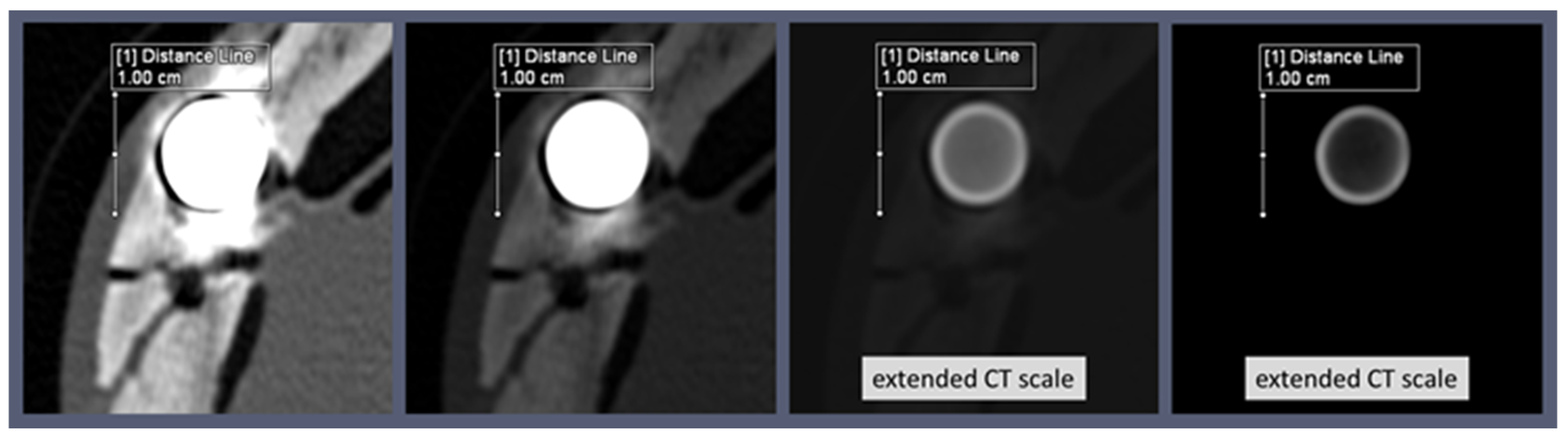
10]. While metal artifact reduction algorithms can minimize the streaks caused by metallic objects in CT images, they do little to enhance the detailed representation of the metallic object itself—in this case, the lodged bullet. A more accurate representation of a lodged bullet can be achieved through reconstructions with extended Hounsfield units (HU) and a high window range [
11]. CT reconstructions typically have a 12-bit depth, allowing for 4096 distinct values (2
12 values). These values, known as CT numbers, are measured in HU, a scale calibrated to distilled water, which is assigned a value of 0 HU. A typical HU scale spans a range from −1024 to 3071 HU. CT images are commonly displayed on medical monitors as 8-bit grayscale images with 256 shades of gray. This limitation makes it impossible to display all 4096 HU values simultaneously, and the human eye cannot discern that many shades of gray even if they were displayed. Human observers can distinguish between 700 and 900 shades of gray simultaneously under optimal conditions and within the luminance range of modern medical displays [
12]. To address this, a technique called windowing is employed. Windowing selects a specific range (the window) on the HU scale for visualization. For a more precise visualization of the shape and size of metallic projectiles in the body, a window range far above 3071 HU is required. Modern CT scanners offer 16-bit reconstructions, allowing for 65,536 grayscale values and a significantly higher window range [
13]. Alternatively, special reconstruction algorithms such as the extended CT scale (or extended HU scale) algorithm can be used [
14]. An extended CT scale reconstruction increases the maximum attenuation value tenfold, from 3071 HU to 30,710 HU and thus allows for a significantly higher window range. Windowing in the upper range of the HU scale effectively eliminates the visibility of metal artifacts, leaving only the shape of the metallic foreign body visible [
15]. Although sometimes interpreted as a metal artifact reduction technique, this technique does not qualify as true metal artifact reduction. Values below the selected window range are simply displayed in black, the same color as the background of a CT image. Therefore, anatomical structures that have HU values below metallic projectiles are rendered invisible (displayed as black) when such a high window area is selected. For the targeted examination of a bullet in the body, however, these reconstructions with extended HU scales allow the bullet itself to be displayed without streaks and distortion (
Figure 1).
In addition to the windowing in a high HU range, the spatial resolution of the reconstructed CT image also has a considerable influence on the representation of the bullet and thus on the accuracy of shape determinations and caliber measurements. For an accurate spatial representation of the bullet, the reconstruction field of view (FOV) must be considered, as it influences the in-plane voxel size [
14]. Users can define the in-plane voxel size according to the size of the reconstructing FOV within the available matrix, which is usually a 512 × 512 matrix. By selecting a smaller reconstruction FOV aligned with the size of the lodged bullet, the resolution of the bullet’s display can be significantly enhanced, allowing for greater detail in its visualization (
Figure 2).
It is important to note that a lodged bullet may still appear distorted on CT images if it is located far from the iso-center of the CT gantry, such as near the edge of the maximum reconstruction field-of-view. This situation may arise, for example, when a bullet is lodged in the upper arm.
CT scan data, being 3D, allow for the virtual rotation of a lodged bullet. However, it is essential to remember that the reconstruction FOV determines the in-plane resolution, while the third dimension is defined by slice thickness, which must be minimized to ensure high resolution in all three dimensions. Multiplanar reconstructions (MPRs) can be utilized to align the dataset with the projectile’s cross-section, enabling precise caliber measurements. Meanwhile, maximum-intensity projections (MIPs) produce X-ray-like images and offer the advantage of allowing the projectile to be virtually rotated as desired. Similarly, the volume rendering technique (VRT) allows for the inspection of the bullet’s shape from all angles and offers several different presets for enhanced visualization. The shape of a lodged bullet can provide valuable information for classification. For instance, the characteristic mushroom shape of a deformed bullet indicates that it is a hollow-point or soft-point bullet. Previous research [
16] has shown that CT reconstructions can provide accurate caliber measurements of a lodged bullet, even with its characteristic mushroom shape, when the measurement is taken at the bullet’s rear end. The degree of mushrooming can also offer insights into the type of bullet. For example, bullets designed for law enforcement use are engineered to mushroom only slightly, reducing the risk of over-penetration and causing a smaller wound cavity compared to conventional hollow-point bullets [
17]. Special law enforcement bullets, designed for controlled deformation and slight mushrooming, often feature internal cavities that are characteristic of the specific bullet type. Examples of such specialized ammunition include the Action 4, SECA (Security Cartridge/Safe Environment Controlled Action), and QD-PEP (Quick Defense—Polizei Einsatz Patrone) bullets. These bullets can be identified on CT images by detecting their internal cavities, and they can even be distinguished from one another based on the distinct shape of these cavities [
17]. Visualizing the interior of these bullets requires 16-bit image reconstruction or extended CT scale reconstructions (
Figure 3).
When a bullet is highly fragmented and deformed, inferring its original shape can be challenging. However, it is still valuable to virtually examine the individual fragments in detail. For example, the shape of specific bullet fragments can help us to identify particular projectile types, such as the G2 Research Radical Invasive Projectile (RIP) [
18,
19,
20,
21]. This bullet consists of a solid base slug and, depending on the caliber, six or eight trocars. As the bullet penetrates tissue, these trocars expand radially, while the base slug continues its path along the trajectory. Identifying the trocars can help classify the bullet type. Virtual examination of the base slug, in addition to counting the trocars, can also aid in caliber measurements. A closer inspection of the fragments may also reveal the bullet’s jacket [
22,
23]. A jacket can be identified when it separates from the core, splitting in such a way that it forms a star-shaped pattern. Such detached jackets are easily visualized on CT scans. If a jacket is detected among the fragments, it can be concluded that the bullet is not a monobloc or monolithic type, which lacks a jacket. Furthermore, the fragmentation pattern can provide clues about the bullet’s metallic composition. For instance, lead bullets fragment differently to copper bullets. However, relying solely on fragments for qualitative distinctions can often be highly unreliable.
4. Material Differentiation (Dual Energy Index)
Whether the lodged bullet is fragmented, deformed, or intact, a CT scan using two different energy levels enables reliable differentiation between lead and copper bullets based on the differences in the HU values between the two energy levels and the specific atomic number (Z) of the metals. Lead (Z = 82) has a higher atomic number than copper (Z = 29), meaning that lead should produce higher HU values due to the strong dependence of the photoelectric effect on the Z value. Based on this, it is tempting to attempt to differentiate between lead and copper bullets using conventional single-energy CT scans. However, this distinction is not always straightforward based on conventional single-energy CT scans, as the X-ray beam is polychromatic, and the effects of beam hardening come into play. Beam hardening causes the edges of metal objects to appear bright, i.e., to have higher HU values (cupping effect). The bright edge of a bullet in CT does not necessarily represent the jacket; it can also be observed in bullets without a jacket. The intensity of the cupping effects varies depending on the metallic element or alloy of the bullet; however, it does not result in significant material differences on CT scans [
24]. Photon starvation in turn causes the HU values to decrease towards the center of the metal object, making the values increasingly unrepresentative of the metal. The values in the center of a bullet or bullet fragment deviate more and more from the values at the edge, depending on its size. The bullet’s location in the body, such as near bones, as well as its orientation, further complicates the material-based discrimination using single-energy CT. However, when CT data are collected at two different energies, the ratio of HU values at these energies can provide a much more reliable method for distinguishing between lead and copper bullets. To achieve this, the dual-energy index (DEI) is calculated as follows:
where x
E1 is the HU value at the lower energy, and x
E2 is the HU value at the higher energy. The “+1000” added to each HU value accounts for the attenuation difference between air and water. The numerator represents the ratio of HU values at the two different energy levels, normalized by their sum in the denominator.
For material-based differentiation, either automated segmentation tools or manual region-of-interest ROI measurements are applied to provide HU values at the same position within the bullet on CT scans acquired at both lower and higher energies [
25]. By calculating the DEI, the influence of factors such as beam hardening is minimized, enabling reliable differentiation between materials, such as lead and copper [
22,
26]. Studies have shown that photon energies obtained from tube voltages of 120 kV and 140 kV are most effective for distinguishing between copper and lead bullets using the dual-energy index [
22,
26]. Despite being called the ‘dual-energy index’, its use for projectile differentiation does not necessarily require a dual-energy CT scanner. In fact, dual-energy CT datasets typically cannot be reconstructed with the extended CT scale. To differentiate metals using the dual-energy index, two single-energy scans can be performed: one at 120 kV and another at 140 kV, specifically targeting the region containing the metallic foreign body. When performing ROI measurements, it is important to ensure that the reconstructions from both CT scans use the same reconstruction kernel, in-plane FOV, slice thickness, and slice increment to maintain consistency (
Figure 4).
For metals with lower atomic numbers, such as copper, the HU values decrease at higher energies, as the X-ray radiation with higher energy penetrates the body more effectively. In contrast, metals with higher atomic numbers, such as lead, show lower HU values at higher energies. This is because medical X-ray radiation, as already mentioned, is polychromatic, i.e., the X-ray beam consists of a spectrum of energies, with a maximum at 120 or 140 keV for tube voltages of 120 kV and 140 kV, respectively. When the average energy of the beam, which is lower at 120 kV than at 140 kV, is closer to the K-edge energy of the metal, as is the case for lead (K-edge energy: approximately 88 keV) at 140 kV, the likelihood of the photoelectric effect increases. This leads to more photons being absorbed by the material, resulting in a lower signal detected by the system and a higher HU value assigned to the voxel. In contrast, copper has a much lower K-edge energy (approximately 9 keV), and this effect does not occur for copper. Accordingly, the DEI, which is based on the difference in HU values between the two energies, provides a reliable method for distinguishing between lead and copper bullets. However, it remains to be investigated how this approach applies to identifying ferromagnetic iron (Z = 26, K-edge energy: approximately 7 keV) or iron-containing steel. The DEI-based differentiation between ferromagnetic (steel-containing) bullets and non-ferromagnetic (non-steel-containing) bullets has been the focus of studies related to magnetic resonance imaging (MRI) safety.
5. Ferromagnetic Components of Bullets (MRI Safety)
In previous studies, the DEI method was evaluated to determine whether it could distinguish lodged projectiles in terms of whether they were ferromagnetic or not; as such, ferromagnetic foreign bodies are a contraindication for MRI [
27]. In 2014, Winklhofer et al. [
28] concluded that DEIs were significantly different between ferromagnetic and non-ferromagnetic bullets, suggesting that dual-energy CT could enhance MRI safety by identifying patients with retained ferromagnetic bullets. However, a study conducted by Diallo et al. [
29] in 2018 on the same topic presented contradictory results regarding the differentiation between ferromagnetic and non-ferromagnetic bullets using the DEI method. This discrepancy can be attributed to the grouping of bullets into ferromagnetic and non-ferromagnetic categories based on their jacket material, while the ROI measurements were conducted on the bullet core, causing the HU values to reflect the properties of lead and copper rather than steel-containing and non-steel-containing jackets [
30]. A grouping error may also have occurred in a 2024 study carried out by van der Merwe and Loggenberg [
31]. The authors reported analyzing one brass bullet (unjacketed), five lead bullets with copper jackets, one lead bullet with a nickel jacket, and four steel bullets with copper jackets, relying solely on ‘physical examination’ for material identification. However, the DEI measurements of the bullet cores suggest that only one bullet actually contained a steel core, as it showed a positive DEI, while all of the other bullets exhibited a negative DEI, which is typical of lead. Therefore, it is crucial to precisely determine the metallic components of a projectile, for example, through scanning electron microscopy with energy-dispersive X-ray spectroscopy (SEM/EDX), before conducting a material differentiation study using CT.
While iron-containing steel can be easily and reliably distinguished from lead using DEI due to their significantly different atomic numbers, distinguishing steel from copper remains unreliable because of their similar atomic numbers. As a result, a lead bullet with a ferromagnetic steel jacket cannot be reliably distinguished from one with a non-ferromagnetic copper or brass jacket using the DEI method, while it is generally possible to differentiate an unjacketed ferromagnetic steel bullet from an unjacketed lead bullet. This means that, if the DEI is determined by the HU values from the bullet core, a steel bullet without a jacket will show a different DEI than a lead bullet with a steel jacket, although both are ferromagnetic. As noted in the previous section, due to beam hardening, it is not possible to reliably identify whether an intact bullet has a jacket using CT imaging; this also complicates the extraction of HU values from the jacket. This limitation applies to conventional energy-integrating detector CTs, although modern photon-counting detector CTs offer greater potential in this regard.
7. Disciplines Involved in Virtual Bullet Examinations
The assessment of lodged projectiles in CT, particularly in forensic contexts, is a critical aspect of modern forensic medicine. In clinical radiology, the interpretation of imaging studies on living patients is typically the responsibility of radiologists. However, when these studies have forensic implications, such as in cases of suspected non-accidental injury or criminal investigations, collaboration between radiologists and forensic specialists becomes essential [
36]. This collaboration ensures that findings are interpreted within the appropriate legal and medical context. Ballistics experts, trained in the identification of bullets, may also play a crucial role in the virtual examination of bullets, contributing to the investigation and assessment process. The virtual assessment of lodged bullets based on stored CT data facilitates remote evaluation and the transfer of information, enabling the seamless integration of various disciplines into the process. This multidisciplinary approach ensures a comprehensive analysis and accurate conclusions in forensic investigations. Equally important are the radiologic technologists, who are skilled in acquiring and reconstructing data from imaging equipment. Their expertise is indispensable in these specialized examinations, ensuring the quality and integrity of the images for further analysis.
The ability to examine projectiles virtually may also be of interest in the context of a non-invasive virtual autopsy, although a projectile can be more easily removed postmortem and then examined thoroughly under the microscope. However, access to CT scanners for postmortem examinations is limited, primarily due to the high costs involved. To successfully implement postmortem CT services, it is essential to align with local needs and effectively tackle challenges concerning access, funding, and data security [
37]. Therefore, the use of postmortem imaging techniques, including CT, varies not only based on institutional resources but also across different geographic regions. Some regions may have advanced facilities and protocols in place, while others may lack the necessary resources to incorporate these methods into routine forensic practice.
Artificial intelligence (AI) is increasingly gaining significance in forensic medicine [
38]. As a result, it is highly likely that AI algorithms will play a key role in visualizing projectiles and differentiating materials, as well as identifying the type of projectile and determining its caliber, especially when the projectile is deformed. The integration of AI into forensic CT scans enhances the identification and analysis of bullet characteristics, even when the projectile remains lodged in the body. As both AI and CT technology continue to evolve, their forensic applications are expected to improve, providing more accurate and comprehensive analyses in future cases, while upholding ethical standards to ensure the integrity of forensic practices.


