Abstract
Enhancing the efficiency of mechanized oil production remains a critical objective in the industry. This paper presents a comparative analysis of existing methods aimed at improving the energy efficiency of oil extraction systems, outlining their respective advantages and limitations. A novel approach is proposed, based on the use of a submersible compensator of reactive power to optimize the performance of electric submersible pumps (ESPs). A mathematical model of the ESP’s electrical system is developed to support the proposed method. Theoretical findings are validated by the experimental studies conducted on operational oil wells. Test results demonstrate a reduction in current consumption by 14.5–20% and an improvement in the power factor from 0.62 to 0.96. These outcomes confirm the effectiveness of the proposed solution in enhancing energy efficiency and reducing electrical losses in oil production processes.
1. Introduction
Today, reducing the financial costs of oil production is a key objective, primarily achieved by improving the energy efficiency of the production process [1,2]. The most common method of extracting oil from wells is mechanized extraction. It requires additional energy to lift the reservoir fluid to the surface [3,4]. This article focuses on mechanized oil production using electric submersible centrifugal pumps (ESPs).
Lifting the reservoir fluid accounts for the largest share of electricity consumption [2,5], ranging from 55% to 62% of the total energy usage among the technological processes involved in mechanized oil production. In ESP-based installations, the distribution of energy losses across the entire system is as follows:
- 40–60% in the centrifugal pump [5];
- 10–15% in the submersible electric motor (SEM);
- up to 15% in the cable;
- up to 12% in the transformer and control station (CS);
- up to 10% in the pump-compressor tubing and wellhead equipment.
The primary consumer of electrical energy within the ESP installations is the submersible electric motor, which drives the shaft of the centrifugal pump. Currently, two types of motors are used in ESPs. They are the induction motors [6] and the permanent magnet synchronous motors [7]. Induction motors with squirrel-cage rotors are the most widely adopted due to their lower cost and higher reliability. It offers a mean time between failures of approximately 790 days under continuous operation, while delivering comparable performance to permanent magnet synchronous motors. However, submersible induction motors have a significant drawback. It is a relatively low power factor. This value typically ranges from 0.8 to 0.84 under nominal operating conditions. A low power factor results in increased power losses in the conductive components of the ESP installations, which can reach up to 40% of the total power consumed [5].
In this article, the squirrel-cage induction motor is selected as the submersible electromechanical energy converter for analysis. Table 1 presents the distribution of energy losses across various components of the ESP installations, along with potential measures to reduce these losses.

Table 1.
The structure of losses in the elements of the ESP installations and measures for their beauty.
Existing methods for enhancing the efficiency of mechanized oil production primarily focus on improving the operational reliability of submersible installations and increasing the energy efficiency of the production process. These methods include the use of high-efficiency equipment, optimization of downhole equipment selection, implementation of energy monitoring systems, development of regulations for energy-efficient design practices, and the adoption of intelligent field technologies [4,8,9,10].
Improving electrical energy utilization and reducing losses relative to total energy consumption in ESP installations can be achieved by several measures. They are increasing the efficiency of the electric centrifugal pump, minimizing hydraulic losses by using tubing with the largest feasible diameter, enlarging the cross-sectional area of cable conductors (especially for cables longer than 1500 m), and employing submersible electric motors with higher operating voltages.
Increasing the tubing diameter (for example, from 73 mm to 89 mm) reduces hydraulic resistance and, consequently, decreases the required pump power. However, this approach is rarely implemented by oil-producing companies due to the increased risk of cable damage caused by the reduced annular clearance between the casing and the tubing.
Enlarging the cross-sectional area of the current-carrying conductors in the cable is a simple and widely applied method to reduce resistive (Joule) losses. However, replacing the existing cable with one of larger cross-section is not always economically viable and requires a case-specific technical and economic evaluation. Additionally, the mechanical integrity of the pump-compressor tubing must be considered, as the increased cable mass resulting from larger conductors can impose additional mechanical loads on the tubing string.
The use of submersible induction motors with elevated voltage levels reduces current flow and, thus, power losses in the cable [11]. However, this solution is predominantly applied to motors with a rated power up to 90 kW. For higher-power motors, increasing the base rated voltage is limited by the dielectric properties of existing insulation materials used in motor windings. Consequently, the challenge of increasing the base voltage for submersible motors exceeding 90 kW remains unresolved.
An analysis of electrical energy loss distribution in ESP installations indicates that the cable and submersible electric motor offer the greatest potential for efficiency improvements. The efficiency of submersible induction motors typically ranges from 0.80 to 0.85 and depends on the motor’s size, rated power, and design configuration. The potential for further reducing mechanical and winding losses is nearly exhausted. While using higher-grade electrical steel with reduced lamination thickness could marginally improve efficiency, the associated increase in material and manufacturing costs renders this approach economically unjustifiable in most practical applications.
Currently available technical solutions for improving power factor at oil fields are typically installed at integrated transformer substations or pump control stations [12,13,14,15,16]. However, these solutions do not provide reactive power compensation directly at the primary load, the submersible asynchronous motor, and therefore do not reduce active power losses in the supply cables, which can be as long as 3500 m.
To enhance the energy efficiency of oil production utilizing ESP installations, the authors of this article propose a novel method involving the direct compensation of reactive power from the submersible electric motor within the downhole [17,18] (Figure 1). Experimental prototypes of submersible compensator of reactive power (SCRP) were developed, and comprehensive theoretical analyses, bench tests, and field trials were carried out to evaluate their performance.
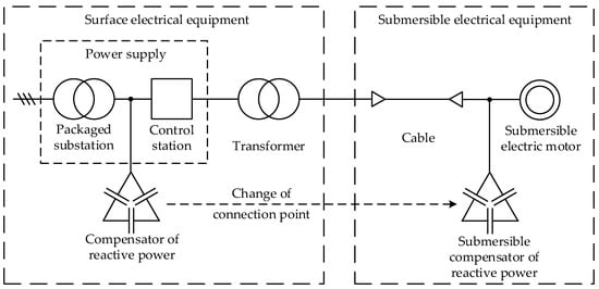
Figure 1.
Generalized functional scheme of an ESP system.
The structure of this paper is as follows: Section 2 introduces the mathematical model of the ESP electrical complex. Section 3 presents the results of the mathematical modeling. Section 4, which details the experimental study outcomes. Section 5 offers a discussion of the findings. Section 6 concludes the work.
2. Object and Methods
The electromechanical subsystem of the ESP installation was selected as the object of study. This subsystem comprises a power source, transformer, cable, submersible electric motor, and a submersible compensator of reactive power.
The generally accepted assumptions and simplifications were adopted in developing the mathematical model:
- The parameters of the components within the ESP installation electrical system are considered linear, with no hysteresis or magnetic saturation effects;
- The electrical circuits in the three-phase system components of the ESP installation are assumed to be symmetrical;
- The system is powered by a balanced set of sinusoidal voltages;
- The cable is assumed to be uniform along its entire length, with no discontinuities or transitions between sections;
- The air gap in the stator bore is uniform, the stator and rotor surfaces in the air gap region are smooth (i.e., without teeth or slots), and there are no eccentricities between the stator and rotor;
- The actual distributed windings of the motor are replaced by equivalent concentrated windings;
- The magnetomotive forces and magnetic field are assumed to be sinusoidally distributed along the circumference of the air gap;
- Higher-order spatial harmonics of the magnetic field are neglected;
- The number of turns in the stator and rotor windings is assumed to be equal.
ESP installation units are typically powered through a control station equipped with a frequency converter featuring an intermediate DC link. The voltage source inverter operates in pulse-width modulation mode. A sine filter is installed at the output of the control station to suppress high-frequency components in the voltage spectrum. The efficiency of modern control stations ranges from 0.95 to 0.98. Therefore, the control station can be modeled as an ideal energy source with negligible power losses for the purposes of this study.
The cable in the ESP installation electrical system transmits electrical energy from the transformer to the submersible motor and the submersible compensator of reactive power. The cable can be represented by an equivalent circuit with either distributed or lumped parameters. The cable is described by a system of partial differential equations in the distributed-parameter model. Ordinary differential equations are used in the lumped-parameter model. The authors propose replacing the distributed-parameter cable model with an equivalent lumped-parameter circuit to simplify calculations and reduce simulation time.
The submersible compensator of reactive power is designed to offset the inductive reactive power of the submersible induction motor. The capacitor bank of the three-phase compensator is connected in a delta (triangle) configuration. In modern power factor correction capacitors, active power losses (primarily due to dielectric losses and viscous friction of dipole molecules) do not exceed 0.5 W per 1000 VAr. Consequently, the active resistance of the compensator can be neglected in the mathematical model without significantly affecting the accuracy of the calculated electrical characteristics.
It is advisable to employ a two-phase orthogonal coordinate system α, β [19] to describe electromechanical processes in three-phase electrical circuits with an electric motor load. In the following analysis of the mathematical models of the components within the electrical system of the ESP installation, we introduce a standard notation for two-dimensional algebraic state vectors of the form:
where X is a column vector representing the projections of a physical quantity onto the α and β axes; the superscript T denotes transposition (used where applicable); t is time.
The equivalent circuit diagram of the ESP electrical complex based on the adopted assumptions and chosen coordinate system is shown in Figure 2.

Figure 2.
Conversion diagram: (a) along the α axis; (b) along the β axis.
The mathematical model of the transformer, expressed in terms of the currents in the primary and secondary windings and the magnetizing branch, can be written in matrix form as:
where i1T, i2T, and imT are the current vectors of the primary winding, secondary winding, and magnetizing branch, respectively, projected onto the α and β axes; u1T is the voltage vector across the primary winding projected onto the α and β axes; L1T′ is the equivalent (referred) inductance of the primary winding; A is the system coefficient matrix.
The expression for the coefficient matrix A is given by the following:
where R1T′ is the equivalent (referred) resistance of the primary winding; R2T and L2T are the resistance and inductance of the secondary winding; RmT and LmT are the resistance and inductance of the magnetizing branch; Rcab and Lcab are the resistance and inductance of the power cable (current-carrying cores).
The mathematical model of the cable, expressed in terms of the secondary winding currents of the transformer and the stator voltage of the submersible induction motor, is given by the following:
where us and is are the vectors of stator voltages and currents of the submersible motor, onto the α and β axes; Ccab is the equivalent capacitance between each phase and the combined reference (other two phases and the armor); gcab is the conductance of the cable insulation; C is the total capacitance of the submersible compensator of reactive power.
The mathematical model of the submersible induction motor, expressed in terms of stator current and rotor flux linkage, takes the following matrix form:
where Ψr is the rotor flux linkage vector, projected onto the α and β axes; B is the system coefficient matrix; ω is the rotor speed; L’r is the total rotor inductance; Lm is the magnetizing inductance corresponding to the magnetic flux in the air gap; Tm(ω) is the electromagnetic torque, including internal friction torque; J is the total moment of inertia referred to the motor shaft; zp is the number of pole pairs of the motor.
System (4) describes the electrical equilibrium in the stator circuit, while system (5) represents the electromechanical equilibrium of the electric motor and its mechanical load.
The coefficient matrix B in Equation (4) is defined as follows:
where Ls is the total stator inductance; R’r is the rotor resistance referred to the stator; Req is the equivalent active resistance of the stator circuit; σ is the leakage (dissipation) factor.
The total stator and rotor inductances, equivalent resistance, and leakage factor are determined by the following:
where L1σ and L′2σ are the stator leakage inductance and the rotor leakage inductance referred to the stator, respectively.
In general, the total mechanical load torque acting on the motor shaft is expressed as follows:
where Tk is the useful (load) torque; ak and bk are coefficients representing constant and variable losses in the pumping system, respectively, under constant efficiency conditions;
ωnom is the nominal rotor speed; γ is the load exponent, with γ = 2 typically representing a pump-type load.
3. Mathematical Modeling
The object of study is the ESP installation equipped with the following components:
- A submersible induction motor, model ED-125-117 (Russia);
- A submersible compensator of reactive power, model VKRM-125-117 (Russia);
- A 2000 m long cable, model KPBK-90 3 × 16 (Russia) [17];
- A transformer, model TMPN-400/3 (Russia).
Transformer parameters are referred to the high-voltage winding. They are presented in Table 2. The equivalent circuit parameters are calculated using the method outlined in [20,21]. The cable parameters are provided in Table 3 [22]. The average temperature of the cable’s conductive core is assumed to be +50 °C.
Table 2.
Parameters of transformer TMPN-400/3.
Table 3.
Parameters of the oil submersible cable KPBK-90 3 × 16.
The reactive power of the submersible compensator of reactive power is 35 kVAr at a nominal voltage of 2080 V and a frequency of 50 Hz. The total capacitance of the SCRP after equivalent transformations is CSCRP = 3 × 34.35 × 10−6 F.
The parameters of the ED-125-117 submersible induction motor are listed in Table 4 [18] and have been verified using standard test protocols. The authors demonstrated that the deviation of the calculated current from experimental data is 0.9%, and it is negative 0.1% for active power consumption, in nominal operating mode. The maximum relative error is 3.0% for current and related deviations within the region of low mechanical loads (40% of nominal load), accounting for permissible measurement uncertainties on test benches (not exceeding 0.5%).
Table 4.
Parameters of the submersible induction motor model ED-125-117.
Mathematical modeling was performed using the Wolfram Mathematica (online version) software platform. Figure 3 shows the rotor speed (a) and electromagnetic torque on the shaft (b) of a submersible induction motor during the startup period. The time interval corresponding to the transient startup phase is indicated.
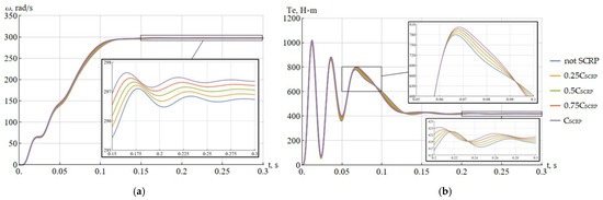
Figure 3.
Rotor speed (a) and electromagnetic torque on the shaft (b) of the submersible electric motor at various relative values of capacitance of SCRP.
Figure 4 presents the time dependencies of the phase-A stator voltage of the submersible induction motor (a) and the phase-A current in the secondary winding of the step-up transformer. It is reached from the moment of startup until steady-state operation.

Figure 4.
Phase A stator voltage of the submersible induction motor (a) and phase A current in the secondary winding of the step-up transformer (b) at various relative values of capacitance of SCRP.
Analysis of the curve in Figure 3a,b shows that increasing the SCRP capacitance leads to a higher speed of the submersible electric motor. This speed increase results from a rise in motor voltage caused by a reduction in current, which in turn decreases the voltage drop in the ESP unit’s electrical system. The higher voltage has a positive effect on the motor’s acceleration time and its electromagnetic torque.
Analysis of the curve in Figure 4a,b reveals that the amplitude of the steady-state current in the transformer’s secondary winding is 71.9 A without the submersible compensator of reactive power connected, and 59.6 A with the submersible compensator of reactive power. Thus, the inclusion of the submersible compensator of reactive power in the ESP electrical system reduces the current by 17.1%.
4. Industrial Testing
A prototype submersible compensator of reactive power with a capacity of 53.5 kVAr was developed at the Almaz-NefteService Llc. plant in Raduzhny to increase the power factor and reduce losses in the ESP electrical transmission complex in 2018. It was achieved by the scientific and technical support of the article’s authors and Tekhoil Research and Production Company Llc. (Figure 5). The prototype is designed to operate as a part of a submersible oil production unit equipped with a two-section submersible electric motor rated at 125 kW, model ED-125-117-M5V5 (Russia). The structural and technological requirements for the submersible compensator of reactive power were conducted jointly with Llc. Almaz during the analysis of the operational performance of submersible equipment and well conditions.
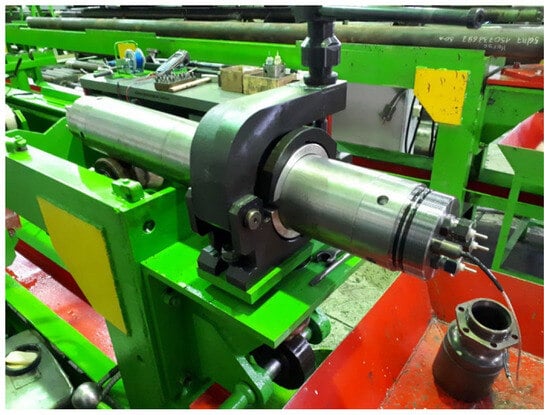
Figure 5.
Prototype of a submersible compensator of reactive power.
Structural:
- The device length does not exceed 4 m, as the submersible compensator is installed below the operational components of the ESP unit and the oil-bearing formation;
- Capability to operate under actual downhole conditions: temperatures up to 140 °C and pressures up to 40 MPa, or in accordance with the requirements of the oil-producing enterprise;
- The devices can be implemented in any standard size (form factor) of submersible equipment;
- Universality; the ability of the developed devices to operate with electric motors from various manufacturers of submersible equipment (subject to appropriate motor retrofitting/modernization).
Technological:
- Setting of required compensation currents for submersible electric motors with a rated power of at least 16 kW;
- Operation with submersible electric motors under variable frequency control in the range of 35 Hz to 70 Hz;
- Operation in parallel with the grid, with voltage harmonic content (3rd, 5th, 7th, etc.) up to 14%;
- Rated voltage up to 3000 V;
- Ability to ensure a power factor at the point of common coupling of not less than 0.95.
Figure 6 illustrates the operating characteristics of the PED-Ya 63–117 M5V5 electric motor, obtained during acceptance tests according to protocol No. 19038-II-II dated 29 August 2018, by Almaz Llc.
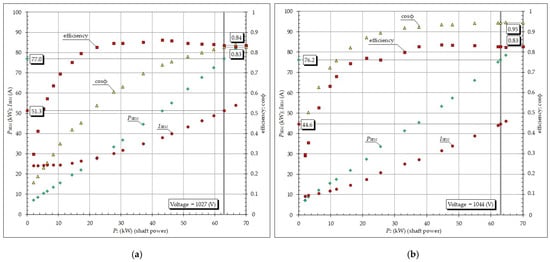
Figure 6.
Dependencies of consumed power, stator current, efficiency, and power factor on shaft power for the submersible electric motor: (a) without SCRP; (b) with SCRP.
Bench tests of the prototype demonstrated a 16% reduction in the current of the submersible electric motor, from 51 A to 42.8 A. Additionally, these tests showed an increase in the power factor from 0.83 to 0.95. At the same time, the input active power and efficiency remained unchanged, because the submersible compensator of reactive power is connected in parallel with the submersible electric motor and does not affect its energy characteristics. The decision of the pilot testing proceeding was made based on these positive results.
Nowadays, six submersibles of reactive power prototypes have been produced, with capacities of 50 kVAr, 53.5 kVAr, and 80 kVAr. Bench test results showed a 20% reduction in current for the submersible induction motors and an increase in the power factor from 0.8 to 0.95, consistent with the test program. A decrease in ESP current ranging from 14.5% to 20% was observed during energy consumption monitoring at the tested oil wells.
The structurally developed submersible compensator of reactive power features a robust, sealed housing designed to withstand external pressures up to 40 MPa. High-temperature capacitors are housed within the unit. The last three prototypes are equipped with protection devices featuring an automatic shutdown function to minimize the risk of premature ESP shutdown in the event of a compensator malfunction and to reduce the costly downtime associated with repair and restoration.
The performance and energy efficiency of the submersible compensators with the reactive power were evaluated at five oil-producing wells. All ESP installations were equipped with Electron-05 control stations (Electron CJSC, Russia), which have a measurement uncertainty of no more than ±1.5%. All recorded physical quantities were taken from these stations. Table 5 presents the parameters of the ESPs usage during these tests.
Table 5.
Technological parameters of the tested ESPs.
The active power consumed by the ESP installation is determined by the power drawn with the submersible electric motor (PSEM) as well as the losses (ΔP) in the power transmission system of the submersible unit.
Active power losses in a cable are determined by its design characteristics, operating temperature, and the submersible motor current. It is shown in Equation (8):
where ISEM is the submersible motor current, in amperes (A); ρ is the conductor resistivity (for copper, ρ = 0.0172 Ω × mm2/m); Lcab is the length of the cable, in kilometers (km); Scab is the cross-sectional area of the cable’s conductive core, in square millimeters (mm2); Twell is the temperature of the cable’s conductive cores, assumed equal to the formation fluid temperature, in degrees Celsius (°C).
Active power losses in the transformer are calculated in Equation (9):
where ΔPno-load represents the no-load losses of the supply transformer, in kilowatts (kW); ΔPshort-circuit denotes the short-circuit losses of the supply transformer, in kilowatts (kW); S and Snom are the full load power and the rated power of the supply transformer, respectively, measured in kilovolt-amperes (kVA).
Losses in modern control stations (ΔPCS) typically account for 2–3% of the total power consumed by the installation. However, according to the technological map of the ESP losses in the control station amount to 7%.
The energy efficiency of each individual well is calculated in Equation (10):
where P’ESP is the active power of ESP with submersible compensators of reactive power.
The electric energy savings over the calculation period, based on the number of working hours per year, are expressed as follows:
where “′” are losses in ESP elements using submersible compensators of reactive power; N is the number of working hours per year, equal to 8760 h.
Table 6 presents the energy characteristics of the ESP before and after the implementation of the submersible compensator of reactive power.
Table 6.
Energy characteristics of the ESP before and after using the SCRP.
5. Discussion
Data analysis (Table 6 and Table 7) indicates that the use of submersible compensators of reactive power reduces the active power consumption of the ESP by lowering the current draw. The primary source of energy savings stems from the reduction in active power losses in the cable lines. For instance, well No. 3 experienced an annual energy consumption reduction of 118.38 MW×year.
Table 7.
Active power losses in ESP system components before and after using SCRP.
The calculated energy efficiency indicator (η) ranges from 5.21% to 11.78%. Specifically, well No. 3 achieved an energy efficiency of 11.78%. It is important to note that the economic benefit is calculated individually for each well and depends directly on the electrical parameters of the ESP electrical transmission complex and the applicable electricity tariff.
6. Conclusions
A mathematical model of the ESP electrical complex with a submersible compensator of reactive power has been developed as a system of ordinary differential equations in the normal Cauchy form. This model enables the analysis of both dynamic and steady-state operating modes of the system.
The characteristics of transient processes within the ESP electrical complex during power-up have been determined. It is established that the use of the submersible compensators of reactive power reduces both the current amplitude and the duration of the transient process upon powering the ESP. Specifically, the current amplitude reaches 71.9 A for the studied ESP without the SCRP, but with the submersible compensators of reactive power, it decreases to 59.6 A, representing a 17.1% reduction in current.
The annual electrical energy savings and corresponding energy efficiency are calculated, ranging from 48.79 MW×year to 118.38 MW×year and from 5.21% to 11.87%, respectively. It is concluded that the application of submersible compensators of reactive power is economically justified, based on these energy efficiency values for the analyzed oil wells equipped with submersible compensators of reactive power. However, this assessment must be performed individually for each well [17].
7. Patents
Patent No. 189025 U1, Russian Federation; IPC H02J 3/18. Submersible compensator of reactive power; Application No. 2018143555, filed on 10 December 2018; published on 7 May 2019. Inventors: V. A. Kopyrin, Yu. E. Bukher, A. L. Portnyagin. Applicant: Llc. NPK Tekhoil.
Author Contributions
Conceptualization, V.K. and A.G.; methodology, Y.I. and R.K.; formal analysis, E.P. and A.G.; resources, V.K.; data curation, V.K. and Y.I.; writing—original draft preparation, V.K. and M.K.; writing—review and editing, E.P. and M.D.; funding acquisition, V.K. All authors have read and agreed to the published version of the manuscript.
Funding
The article is prepared as part of a grant for the Industrial University of Tyumen (project “Software and Hardware complex for on-line diagnostics of electrical equipment”).
Data Availability Statement
The original contributions presented in this study are included in the article. Further inquiries can be directed to the corresponding author.
Conflicts of Interest
The authors declare no conflicts of interest.
References
- Petrochenkov, A.; Lyakhomskii, A.; Romodin, A.; Perfil’eva, E.; Mishurinskikh, S.; Zuev, S.; Butorin, I.; Kolesnikov, N.; Lelekov, A.; Shabunin, A. Improving the Energy Efficiency of an Electric Submersible Pump Installation Using an Integrated Logistics Support Approach. Sustainability 2023, 15, 11845. [Google Scholar] [CrossRef]
- Liang, X.; Xing, Z.; Yue, Z.; Ma, H.; Shu, J.; Han, G. Optimization of Energy Consumption in Oil Fields Using Data Analysis. Processes 2024, 12, 1090. [Google Scholar] [CrossRef]
- Petrochenkov, A.; Ilyushin, P.; Mishurinskikh, S.; Kozlov, A. Development of a Method for Improving the Energy Efficiency of Oil Production with an Electrical Submersible Pump. Inventions 2023, 8, 29. [Google Scholar] [CrossRef]
- Ramzey, H.; Badawy, M.; Elhosseini, M.; Elbaset, A.A. I2OT-EC: A Framework for Smart Real-Time Monitoring and Controlling Crude Oil Production Exploiting IIOT and Edge Computing. Energies 2023, 16, 2023. [Google Scholar] [CrossRef]
- Grassian, D.; Olsen, D. Detailed Energy Accounting of Electrical Submersible Pumping Systems. Energies 2020, 13, 302. [Google Scholar] [CrossRef]
- Çunkaş, M. Design Optimization of Electric Motors by Multiobjective Fuzzy Genetic Algorithms. Math. Comput. Appl. 2008, 13, 153–163. [Google Scholar] [CrossRef]
- Beck, M.; Sperlich, A.; Blank, R.; Meyer, E.; Binz, R.; Ernst, M. Increasing Energy Efficiency in Water Collection Systems by Submersible PMSM Well Pumps. Water 2018, 10, 1310. [Google Scholar] [CrossRef]
- Zou, Y.; Zhou, D.; Ma, X.; Jie, Y.; Wang, X.; Liu, H. Optimization of Mathematical Function-Shaped Fracture Distribution Patterns for Multi-Stage Fractured Horizontal Wells. Energies 2023, 16, 4987. [Google Scholar] [CrossRef]
- Alemi, M.; Jalalifar, H.; Kamali, G.R.; Kalbasi, M. A mathematical estimation for artificial lift systems selection based on ELECTRE model. J. Pet. Sci. Eng. 2011, 78, 193–200. [Google Scholar] [CrossRef]
- Xu, J.; Li, J.; Chen, J.; Han, M.; Han, X.; Li, J. Research on Power Saving Positive Torque and Constant Power Pumping Unit and Tracking Technique System. Procedia Eng. 2012, 29, 1034–1041. [Google Scholar] [CrossRef]
- Luk, P. Design Challenge of High-Speed High-Power Density Motor for Advanced Electrical Submersible Pump. In Proceedings of the 2023 IEEE International Electrical Machines & Drives Conference (IEMDC), Dallas, TX, USA, 15–18 May 2023; pp. 1–6. [Google Scholar]
- Kosobudzki, G.; Dusza, D.; Ciurys, M.P.; Leicht, A. Reactive Power Compensation for Single-Phase AC Motors Using Integral Power Theory. Energies 2025, 18, 2641. [Google Scholar] [CrossRef]
- Sui, X.; Han, G.; Lu, X.; Xing, Z.; Liang, X. Energy Consumption Prediction and Optimization of the Electrical Submersible Pump Well System Based on the DA-RNN Algorithm. Processes 2025, 13, 128. [Google Scholar] [CrossRef]
- Malyar, A.; Cieslik, S. Calculation of Processes in the Electric Drive of the Sucker-Rod Pumping Unit with Reactive Power Compensation. Energies 2023, 16, 7782. [Google Scholar] [CrossRef]
- Yidi, S.A.G.; Santos, V.S.; Sarmiento, K.B.; Candelo-Becerra, J.E.; de la Cruz, J. Comparison of Reactive Power Compensation Methods in an Industrial Electrical System with Power Quality Problems. Electricity 2024, 5, 642–661. [Google Scholar] [CrossRef]
- Sobhy, M.A.; Hegazy, G.M.; El-Banbi, A.H. Dual-Level Electric Submersible Pump (ESP) Failure Classification: A Novel Comprehensive Classification Bridging Failure Modes and Root Cause Analysis. Energies 2025, 18, 3943. [Google Scholar] [CrossRef]
- Kopyrin, V.A.; Deneko, M.V.; Markova, A.A.; Pashina, A.V.; Khamitov, R.N. Determination of the Economic Efficiency from the Downhole Compensators’ Introduction, under the Average Elaboration to Failures. In Proceedings of the 2021 Dynamics of Systems, Mechanisms and Machines (Dynamics), Omsk, Russian, 23–25 November 2021; pp. 1–4. [Google Scholar] [CrossRef]
- Glazyrin, A.S.; Isaev, Y.N.; Kopyrin, V.A.; Timoshkin, V.V.; Kladiev, S.N.; Khamitov, R.N.; Kovalev, V.Z.; Losev, F.A.; Leonov, A.P.; Popov, E.I. Transient Processes in electrical Complex of a Production Well with a Downhole Reactive Power Compensator. Bull. Tomsk. Polytech. Univ. Geo Resour. Eng. 2023, 334, 168–180. [Google Scholar] [CrossRef]
- von Jouanne, A.; Agamloh, E.; Yokochi, A. A Review of Matrix Converters in Motor Drive Applications. Energies 2025, 18, 164. [Google Scholar] [CrossRef]
- Mossad, M.I.; Azab, M.; Abu-Siada, A. Transformer Parameters Estimation from Nameplate Data Using Evolutionary Programming Techniques. IEEE Trans. Power Deliv. 2014, 29, 2118–2123. [Google Scholar] [CrossRef]
- Ćalasan, M.; Mujičić, D.; Rubežić, V.; Radulović, M. Estimation of Equivalent Circuit Parameters of Single-Phase Transformer by Using Chaotic Optimization Approach. Energies 2019, 12, 1697. [Google Scholar] [CrossRef]
- Glazyrin, A.S.; Isaev, Y.N.; Kladiev, S.N.; Leonov, A.; Rakov, I.; Kolesnikov, S.; Langraph, S.V.; Filipas, A.; Kopyrin, V.; Khamitov, R.N.; et al. Determination of Linear Electrical Parameters of an Oil-Submersible Cable. Bull. Tomsk. Polytech. Univ. Geo Resour. Eng. 2021, 332, 186–197. [Google Scholar] [CrossRef]


Disclaimer/Publisher’s Note: The statements, opinions and data contained in all publications are solely those of the individual author(s) and contributor(s) and not of MDPI and/or the editor(s). MDPI and/or the editor(s) disclaim responsibility for any injury to people or property resulting from any ideas, methods, instructions or products referred to in the content. |
© 2025 by the authors. Licensee MDPI, Basel, Switzerland. This article is an open access article distributed under the terms and conditions of the Creative Commons Attribution (CC BY) license (https://creativecommons.org/licenses/by/4.0/).