Abstract
This research investigates the positioning performance of the L-band Digital Aeronautical Communications System (LDACS) and presents a system architecture based on carrier-smoothed ground-to-air pseudoranges (PRs), along with clock corrections derived from asymmetric two-way time and frequency transfer (A-TWTFT) filters. The objective is to achieve required positioning accuracy and integrity for aviation operations, addressing the complexities associated with utilizing a terrestrial communications system for complementary positioning, navigation, and timing (CPNT). Through error covariance analysis, this study assesses the steady-state value, convergence time, and bounding performances of the filters. The positioning performance highlights the benefits provided by the proposed architecture.
1. Introduction
This paper summarizes the positioning capabilities of the L-band Digital Aeronautical Communications System (LDACS) and introduces a system architecture that capitalizes on the availability of continuous ground-to-air pseudorange (PR) and carrier phase measurements while using lower rate air-to-ground measurements to estimate the air–ground clock offset to improve solution geometry. The clock offset estimation is accomplished using a novel asymmetric two-way time and frequency transfer (A-TWTFT) methodology. The overall objective of this research is to enhance positioning accuracy and integrity for civil aviation, tackling the challenges posed by the use of a terrestrial communications system for complementary navigation. There have been demonstrations and analysis, conducted primarily at DLR, that have demonstrated the feasibility of ranging with LDACS to support alternative or complementary positioning, navigation, and timing (APNT and CPNT, respectively) in case of disruptions to signals from global navigation satellite systems (GNSSs). In addition to current civil aviation operations, CPNT capabilities will be especially critical for emerging advanced air mobility (AAM) systems. These systems will operate at lower altitudes than conventional fixed-wing air transport aircraft, and existing terrestrial navigation aids will likely not be able to satisfy AAM navigation performance requirements. This paper begins with a description of the proposed CPNT system architecture, with an emphasis on the measurement generation and error models. The next sections describe the A-TWTFT process in more detail, followed by a presentation of the positioning simulation results. These results illustrate the benefits gained in terms of positioning availability through the use of A-TWTFT processing.
2. LDACS PNT: Proposed System Architecture
2.1. LDACS Overview
LDACS is a cellular communication system that is proposed to co-exist in the L-band spectrum currently used by distance measurement equipment (DME) [1]. LDACS employs orthogonal frequency division multiplexing (OFDM) signal modulation with a bandwidth of roughly 500 kHz, which provides a ranging accuracy sufficient to meet the aviation required navigation performance (RNP) for enroute-to-terminal operations. The airspace is divided into logical cells, each managed by a controlling GS responsible for the air–ground communications in that cell. Aircraft or aircraft stations (ASs) within a cell can establish authenticated connections with the controlling GS. The GS utilizes a frequency division duplexing scheme to establish a bidirectional data link with the aircrafts under their control. This approach uses separate frequencies for the forward link (FL), transmitted from ground to air, and the reverse link (RL), transmitted from air to ground. The FL is broadcast continuously, while the RL is shared among the ASs using a time division multiple access (TDMA) protocol. In order to enable PNT, the cells have to geographically overlap and have adequate frequency planning to avoid interference between neighboring cells and legacy radio systems.
2.2. Measurements Processing and Protocols
2.2.1. Protocol Overview
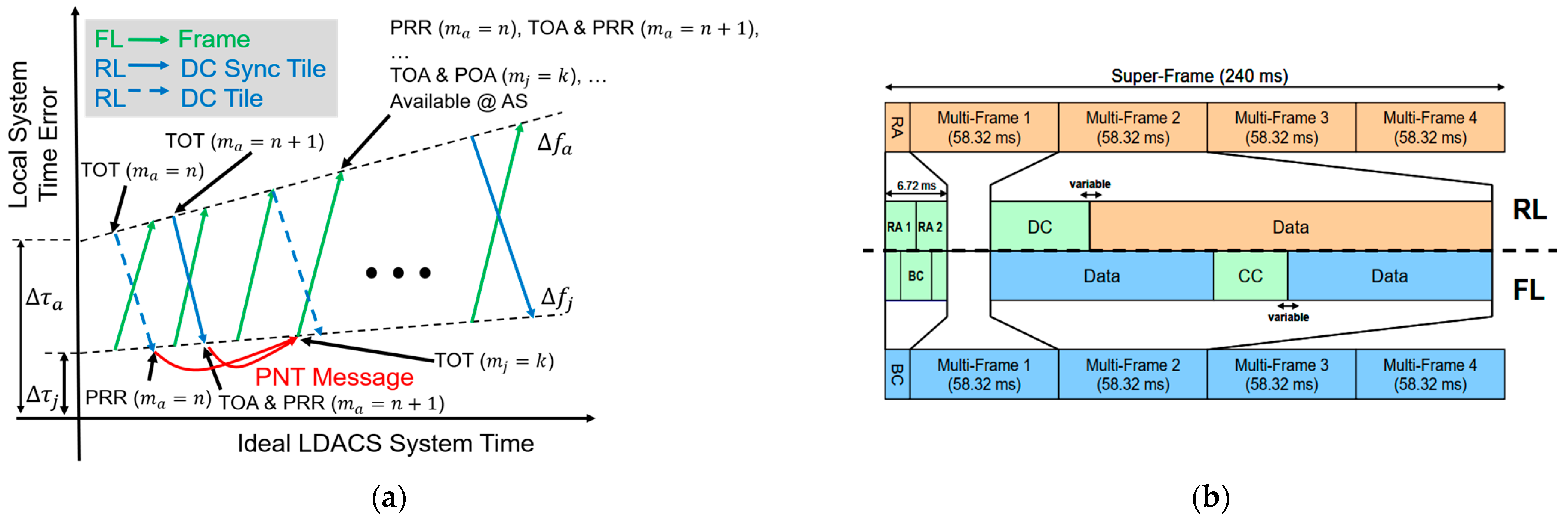
FL and RL signals have different framing structures that align at the super-frame (SF) and multi-frame (MF) boundaries, at 240 ms and 58.32 ms, respectively [1]. Figure 1 illustrates this concept, where the transmissions are aligned with respect to the LDACS system time (LST), and the clock phase and frequency errors are shown to illustrate the actual clock behavior. Each SF is identified by an index which is derived from the SF counter available in the FL broadcast control (BC) message. The LST definition and messaging is included in the LDACS Standards and Recommended Practices (SARPs) as part of the International Civil Aviation Organization (ICAO) standardization activities. This is a crucial step to “future proof” PNT services over LDACS [2,3]. In addition to the BC message, which is broadcast to all controlled ASs, a dedicated and authenticated PNT application enables navigation data exchange, including the forwarding of RL measurements made by the GS, for each GS–AS pair. Thus, the AS’s navigation processor has access to the FL and RL measurements, corrections, and additional PNT parameters.
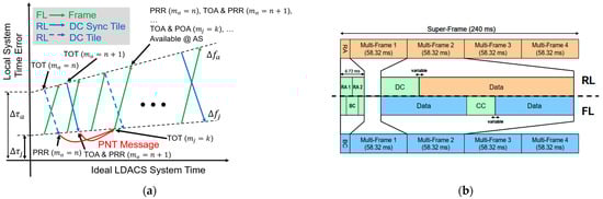
Figure 1.
(a) Illustration of FL and RL measurements and (b) FL and RL super-frame structure [1].
Time synchronization is critical to enabling pseudoranging-based navigation. Each GS needs to include a timing subsystem responsible for synchronizing the local clock to LST. The initial requirements and considerations are presented in [4]. In this work, we assumed a 50 ns root-mean-square (RMS) network synchronization, which is representative of the performance of readily available synchronization technologies. The AS synchronizes its transmissions with the controlling GS to enable collision-free TDMA operation on the RL. However, the capability of the LDACS to provide two-way pseudoranging measurements using both the FL and RL allows for the determination of air–ground clock offsets, which, as demonstrated here, leads to enhanced positioning availability. It is noteworthy that the GS measurements of RL for each AS occur relatively infrequently (sub-Hz rate), whereas the AS can measure the FL at a higher rate (>4 Hz). This asymmetry between the FL and RL signals complicates the estimation of the air–ground clock offsets. The proposed processing architecture addresses this challenge.
2.2.2. Pseudorange and Doppler Measurement Models
FL and RL message time-of-arrivals (TOAs) can be estimated by the AS and GS receivers using the synchronization sequences in the signal structure. Similarly, phase-of-arrival (POA) and Doppler can be computed using the synchronization sequences and the pilot symbols. The FL time-of-transmit (TOT) is derived from the FL transmission schedule. The FL BC messaging includes a provision for up-linking known TOT offsets. These timing offsets could include known clock and radio frequency front-end calibration errors. After decoding the BC PNT data, the aircraft can derive the FL TOT. The FL code PR for the message is constructed as follows:
where is the true range between the “j-th” GS and the AS “a”, c is the speed of light, and are the clock phase offsets, and are the residual group delay calibration errors of the transmitter/receiver front ends, is the residual tropospheric delay after correction, and is the error term accounting for multipath and unmodeled effects. Additionally, is defined as the clock phase difference between the AS and GS clocks in meters, while is the combined effect of the AS and GS residual calibration errors. Note that is the true time of the message according to the ideal LST time. The time variable notation is dropped here in order to improve readability. The FL phase PR is modeled as follows:
where is the combined phase calibration error on the FL phase PR, represents phase multipath and additional errors, and and are the carrier integer ambiguity and wavelength, respectively. The receiver also provides the PR rate (PRR) or Doppler from either block processing (e.g., differentiating phase PRs) or directly from a phase-lock loop numerically controlled oscillator rate value. The simplified PRR model is expressed as follows:
where is the true range rate, is the clock frequency difference in meters per second, and accounts for multipath and other errors. The variations of and are assumed to be negligible over the measurement interval. The same structure in Equations (1)–(3) are used to express the RL measurements after reversing the subscript order in each term, e.g., .
2.2.3. FL and RL Processing Considerations
The FL signal-in-space (SIS) can support high measurement rates. A practical and convenient assumption is that FL code and phase PRs are made so that they are valid at the SF boundary, yielding an update interval of 240 ms. In the RL, the update time of code PR and PRR measurements is dictated by the number of logged airplanes. The allocation is handled by the controlling GS and, for different algorithms and number of ASs, the RL code PR update time can vary from a minimum of 240 ms to 12 s or more. The RL PRR is similar, but it is possible to obtain measurements every 240 ms through the “keep-alive” message present in each SF [1]. For our analysis, we assumed an RL PRR update time of 240 ms and an RL code PR update time that can vary from 240 ms up to 1 min, valid at the SF boundary, similar to the FL.
2.3. PNT Airborne Architecture
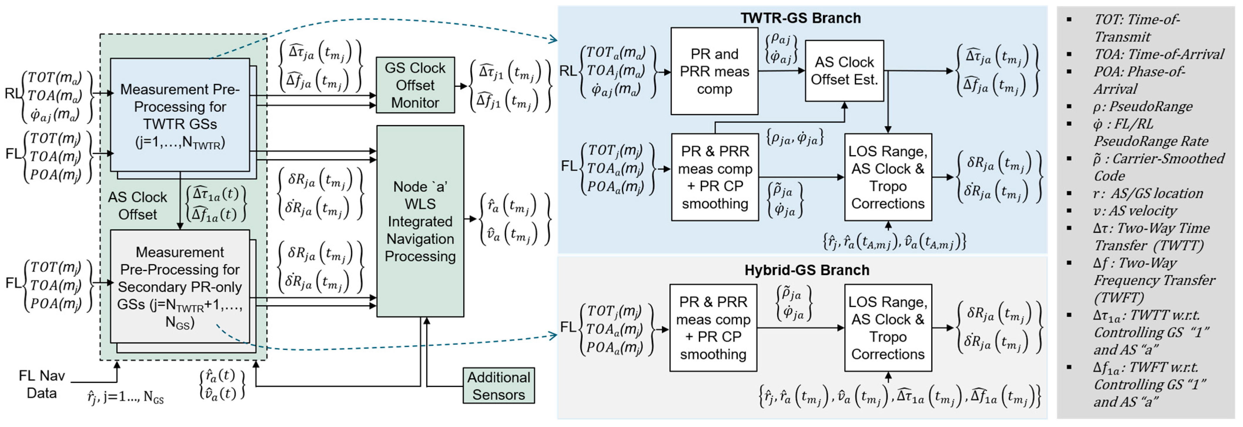
LDACS can support three positioning and measurements modes: PR, two-way timing and ranging (TWTR), and the hybrid combination of PR and TWTR [2,3,4,5]. Figure 2 illustrates the measurement process for the hybrid mode. This architecture processes the measurements and navigation data incoming from stations. The process is split into two major branches: “TWTR-GS” and “Hybrid-GS”. The first one processes the FL and RL info from the first GSs, while the second processes the FL info from the remaining GSs. In both branches, the FL code and Phase PRs are generated and then processed by the smoothing filter. The FL carrier-smoothed code (CSC) is then linearized, and together with the PRR corrected for modeled errors, e.g., tropospheric delay. The “TWTR-GS” branch additionally generates the RL PR and PRRs and combines them with the FL pair processes them in the A-TWTFT filter. The filter estimates the clock phase and frequency differences for each of the GSs, which are then used to correct all the FL CSCs and PRRs in the hybrid mode. These corrections are not applied in the PR mode.
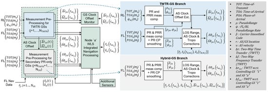
Figure 2.
LDACS PNT airborne architecture overview—hybrid positioning mode.
This architecture assumes a complementary filter to provide a smoothed estimate of carrier ambiguity under the influence of a time-correlated multipath channel. Following the theory in [6], an additional Gauss–Markov state is included to augment the filter and bound the errors introduced by the propagation channel. The same approach is used for the A-TWTFT filter and is discussed in detail in Section 3. The FL carrier-smoothed code (CSC) is described as follows:
where is the residual calibration error after smoothing, and is the estimation error. The clock corrections are applied to the FL CSCs on both the conceptual TWTR and PR branches (Figure 2). Equations (5) and (6) describe the smoothed and clock corrected FL PRs as output from the two branches:
where is the residual timing filter error, and is the time synchronization error between the controlling GS named “1st” and a “j-th” GS. Clearly, has a larger overall error budget compared to due to the term. The integrated navigation processing block in Figure 2 estimates the unknown state update vector as the weighted least-squares (WLS) solution to the linearized system of equations as follows:
where is the residual vector, is the geometry matrix, and is the WLS weighing matrix, which is the inverse of the measurement covariance matrix. The system of equations is augmented with measurements from an altimeter sensor to reduce the dilution of precision (DOP) and enlarge the geographic area of service [5].
3. Asymmetric Two-Way Time and Frequency Transfer (A-TWTFT)
Let us consider the state estimation problem of clock-to-clock phase and frequency differences between the AS and GS clocks. The differences are observed over an asymmetric bidirectional radio channel affected by time-correlated multipath errors. In this work, we consider a first-order Gauss–Markov process (GMP) to model the effect of multipath ranging errors on both FL and RL PRs.
3.1. Observables
Two-way time transfer (TWTT) between the GS and AS is obtained by combining the FL and RL PRs that have similar or identical time validity. The observable TWTT is defined as follows:
where is the code multipath, and represents the unmodeled effects. Since the FL and RL operate on different frequencies, it is appropriate to assume that the noise and multipath terms are uncorrelated but are statistically identical. It follows that
The observable two-way frequency transfer (TWFT) is obtained combining the FL and RL PRRs, as follows:
where the PRR multipath is small, and its effect is captured together with other effects in . With the same assumptions of Equation (9), we can define . Calibration errors are not modeled in Equations (8) and (10), as they are captured in the final error budget as miscellaneous errors in Table 1. The corrections provided directly by Equations (8) and (10) are valid in the past due to the delay it takes to transfer the RL PR and PRR data from the GS to the AS PNT processing unit. In order to overcome this issue, we introduced a Kalman filter (KF) that processes the measurements in the past and propagates the estimates to the current time.

Table 1.
Analysis parameters.
3.2. Filter Design
The process to be estimated is described as a discrete time linear dynamic system, as follows:
The state vector is composed with the clock difference states and the multipath state. The standard two-state model is used for the clock difference, where the noise contribution comes from white frequency modulation (WFM) and random walk frequency modulation (RWFM) [7]. The 3rd state is a GMP, which is used to model the time-correlated multipath errors on the TWTT measurements. We express the state transition matrix and process noise as:
where and are the diffusion coefficients that define the WFM and the RWFM, respectively. is described in Equation (9) starting from m RMS, which represents a 50% overbound to the result in [8]. The time constant ranges from 0 to 20 s to account for modeling uncertainty. The process observables, and , are measured at discrete time instances and and are modeled as follows:
The measurement matrices and link the process states to the two types of measurements.
We propose a KF design that uses the same three-state model structure as the process in Equation (11), but in order to bound the multipath time correlation, the GMP parameters, and , are used. These are defined according to [6], where the true GMP parameters are assumed to have uncertainty in the ranges of seconds and meters. Hence, the actual process and filter transition matrix and process noise differ only by the terms and . The filter TWTT and TWFT measurement matrices and noises are the same as the true process. Note that due to the asymmetry in the FL and RL channels, the and might not coincide, and the filters process the measurements at different rates. In practice, it is possible to process the measurements one at a time since they have uncorrelated noises, and [7].
4. A-TWTFT Numerical Results
The proposed A-TWTFT filter parameters intentionally deviate from those of the actual process. Therefore, in order to evaluate the filter performance, we utilized the theory of error covariance analysis described in [6,9]. This section presents the results of the analysis in terms of the TWTT-state RMSE, convergence time, and bounding performance for different TWTT update intervals .
4.1. Analysis Parameters
Let us consider a rubidium atomic clock (Rb) for the GS and a temperature compensated crystal oscillator (TCXO) for the AS. The clocks WFM and RWFM diffusion parameters are derived from their Allan variance data presented in [7]. The TWTT measurement noise is defined from Equation (9), where an 8 m RMS for both FL and RL PRs is considered [5]. The TWFT measurement noise is 12.70 cm/s RMS; the derivation is not presented in this paper. Lastly, the measurements updates intervals and stem directly from Section 2.2.3.
4.2. Results
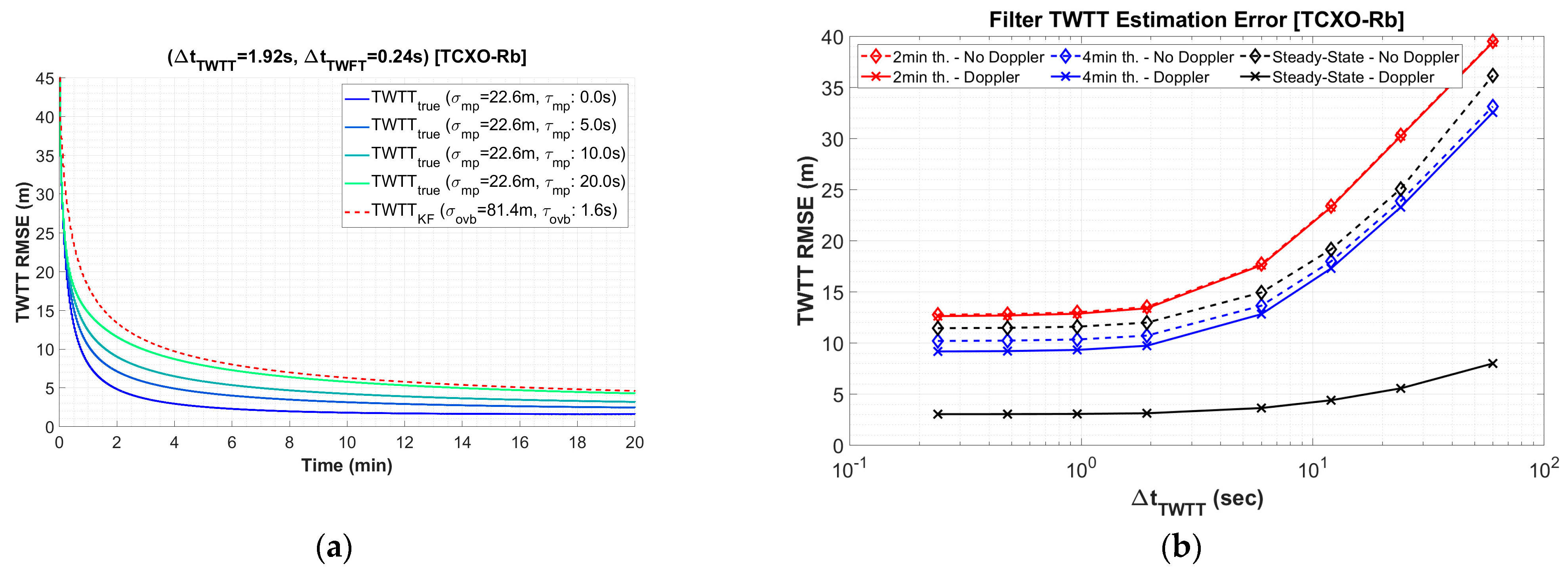
Figure 3 provides a summary of the TWTT-state estimation results with Doppler and/or PR measurements. Figure 3a shows the RMSE TWTT values of the true process and of the KF (with Doppler) for = 1.92 s. The KF consistently bounds the true process across various values.
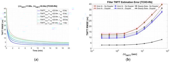
Figure 3.
Error covariance analysis results: (a) TWTT-state RMSE results for = 1.92 s with Doppler. (b) Summary of KF TWTT-state RMSEs for different values with/without Doppler.
Figure 3b summarizes the KF TWTT-state RMSEs for different values, illustrating the RMSEs at 2–4-min thresholds and at steady state, while comparing results with and without Doppler. Clearly, Doppler significantly reduces the steady-state value, although the benefit diminishes at the 4 min threshold and becomes negligible at the 2 min threshold. Therefore, the filter behaves similarly during the initial minutes. However, over the long term, the Doppler measurements decreased the covariance growth in the filter prediction step, thereby reducing the steady-state RMSE. Looking closely at Figure 3b, it can be seen that the filter without Doppler exhibits overshoot behavior, as the steady-state is larger than the 4 min threshold. In this case, the filter relies solely on the PR observations to estimate the three-state vector and it takes several minutes to reach the steady state. Figure 3b shows that for values spanning from 240 ms to 1.92 s, the TWTT performance is similar, whereas for values larger than 1.92 s, the 2 and 4 min thresholds notably increase. These findings can inform the design of a “fast-update” protocol, where a subset of ASs could be prioritized, e.g., receiving TWTT updates at 1.92 s for about 2 min and then switching to a slow 12 s update cycle.
5. Positioning Performance
5.1. Coverage Analysis
Let us consider a network made with five candidate sites that could be used in a planned SESAR-sponsored flight campaign. This is representative of a plausible early deployment layout. The candidate GSs are located in the region south-west of the DLR campus in Oberpfaffenhofen. Our focus was on assessing the horizontal position error (HPE) of the proposed architecture. We computed the coverage percentage within a 50 NM radius area from the geometric center of the network for two services: automatic dependent surveillance broadcast (ADS-B) navigation accuracy category 8 (NACp 8), with a 92.6 m accuracy threshold, and RNP 0.3, with a 307.1 m accuracy threshold. Measurements from a barometric altimeter were used to augment the WLS solution in Equation (7). The error budget for the altimeter was derived from the procedure described in [5]. We assumed ground omnidirectional antennas with a constant gain between elevations of 0.5 deg and 40 deg. The service radius of each GS was conservatively considered 84 NM due to the limitation on the maximum transmit power. Terrain occlusion was included in the analysis. When analyzing the hybrid mode, only the controlling GS in Oberpfaffenhofen was assumed to be TWTR-enabled. Table 2 presents the FL CSC error budget for the three ranging modes.
Table 2.
CSC FL PR error budget for each ranging mode.
The TOA multipath error, 16 m, represents the RMS value obtained after a 2 min filtering with a smoothing time constant of 100 s. Meanwhile, the TWTT estimation error, 14 m, was derived from a 2 min threshold for = 1.92 s or a 4 min threshold for = 6 s. Considering typical operational durations, approximatively 20 min, 2–4 min thresholds are a reasonable assumption for this “snapshot” analysis. The miscellaneous error term accounts for the contributions of thermal noise, calibration, siting, residual tropospheric delay, and TOT modeling errors.
5.2. Results
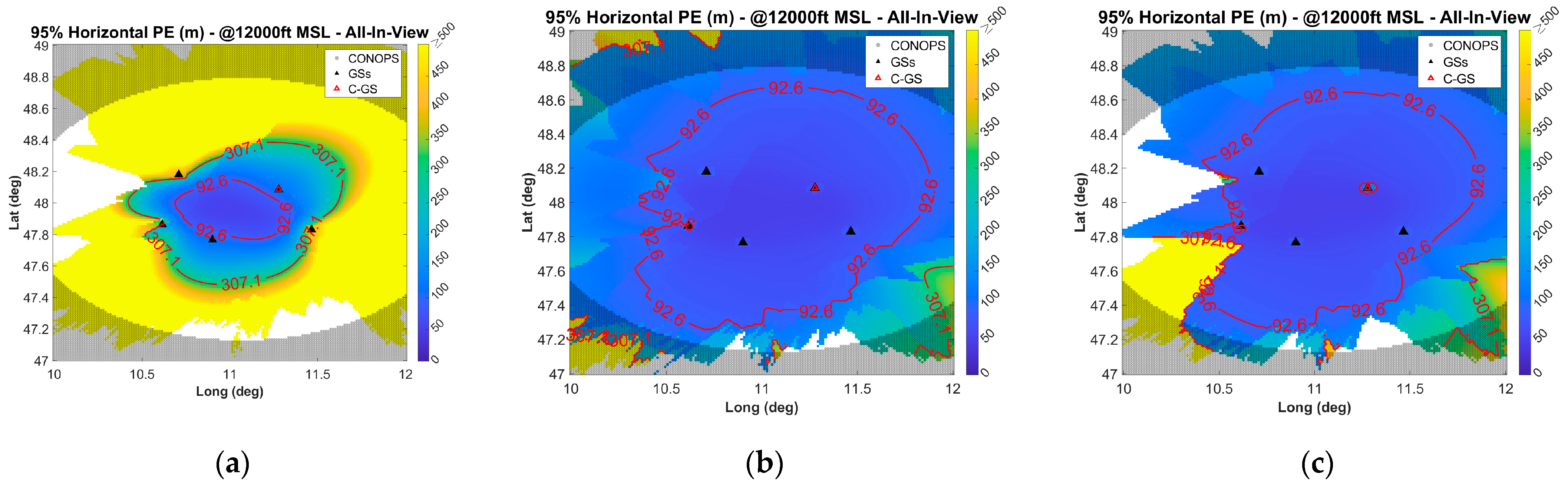
Figure 4 illustrates the 95% HPE of the three modes for a grid of potential user locations at a 12,000 ft altitude. Although the error budget remains similar across the ranging modes, the results distinctly show the superior performance of the TWTR and hybrid modes (Table 3). The enhanced service coverage stems from the significant reduction in DOP [4,5]. Note that for loosely synchronized networks (e.g., 100 ns or worse), the hybrid and PR modes will suffer an increase in the error budget and subsequently the HPE, whereas the TWTR mode is not impacted.
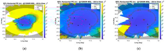
Figure 4.
Example of 95% HPE for operation at 12,000 ft: (a) PR mode; (b) TWTR mode; (c) hybrid mode. The grey dots indicate regions not evaluated due to the operational zone (50 NM radius).
Table 3.
HPE accuracy—coverage percentage over 50 NM radius at 12,000 ft.
6. Conclusions
This paper analyzes the A-TWTFT filter performance using Doppler and/or PR measurements over a time-correlated multipath channel. The proposed KF is tailored to handle the FL and RL asymmetry while bounding the true process for various PR update times, and true process parameters. The introduction of Doppler measurements reduces the filter’s steady-state estimation error and provides insights for future algorithm developments. The positioning analysis shows the superior performance of the TWTR and hybrid modes and the crucial role of the smoothing filters. Lastly, the characterization of multipath has a substantial impact on the overall system performance. To develop more precise models, additional data and thorough analysis are essential.
Author Contributions
Conceptualization, G.Z., G.M. and M.M.; methodology, G.Z. and G.M.; software, G.Z.; validation, G.Z. and B.W.; formal analysis, G.Z.; investigation, G.Z.; resources, G.Z. and G.M.; data curation, G.Z.; writing—original draft preparation, G.Z.; writing—review and editing, G.Z., G.M., B.W. and M.M.; visualization, G.Z.; supervision, M.M. and G.M.; project administration, M.M. and G.M.; funding acquisition, M.M. All authors have read and agreed to the published version of the manuscript.
Funding
This project received funding from the SESAR 3 Joint Undertaking (JU) under grant agreement No. 101114844.
Institutional Review Board Statement
Not applicable.
Informed Consent Statement
Not applicable.
Data Availability Statement
The data presented in this study are available upon request.
Conflicts of Interest
Author Gary McGraw was employed by the company Genova Technologies. The remaining authors declare that the research was conducted in the absence of any commercial or financial relationships that could be construed as a potential conflict of interest.
References
- SESAR2020-PJ14-W2-60; Initial LDACS A/G Specification. SESAR Joint Undertaking: Brussels, Belgium, 2020.
- McGraw, G.; Zampieri, G.; Osechas, O.; Meurer, M.; Kalyanaraman, S. LDACS APNT Protocol and Measurement Signal Processing Architecture. In Proceedings of the 2023 International Technical Meeting of The Institute of Navigation, Long Beach, CA, USA, 24–26 January 2023; pp. 11–25. [Google Scholar]
- McGraw, G.A.; Zampieri, G.; Filip-Dhaubhadel, A.; Osechas, O.; Meurer, M. LDACS APNT Architecture Development & Evolution. In Proceedings of the 2023 IEEE/ION Position, Location and Navigation Symposium (PLANS), Monterey, CA, USA, 24 April 2023; IEEE: Monterey, CA, USA, 2023; pp. 1126–1135. [Google Scholar]
- Zampieri, G.; McGraw, G.; Osechas, O.; Weaver, B.; Meurer, M.; Kalyanaraman, S. LDACS Navigation System Design Considerations. In Proceedings of the 35th International Technical Meeting of the Satellite Division of The Institute of Navigation (ION GNSS+ 2022), Denver, CO, USA, 20 October 2022; pp. 261–275. [Google Scholar]
- Zampieri, G.; McGraw, G.A.; Osechas, O.; Weaver, B.; Meurer, M. LDACS APNT Service Area Analysis with Barometric Altimeter Augmentation and Ground Station Selection Constraints. In Proceedings of the 36th International Technical Meeting of the Satellite Division of The Institute of Navigation (ION GNSS+ 2023), Denver, CO, USA, 15 September 2023; pp. 727–738. [Google Scholar]
- García Crespillo, O.; Langel, S.; Joerger, M. Tight Bounds for Uncertain Time-Correlated Errors With Gauss–Markov Structure in Kalman Filtering. IEEE Trans. Aerosp. Electron. Syst. 2023, 59, 4347–4362. [Google Scholar] [CrossRef]
- Brown, R.G.; Hwang, P.Y.C. Introduction to Random Signals and Applied Kalman Filtering: With MATLAB Exercises, 4th ed.; John Wiley: Hoboken, NJ, USA, 2012; ISBN 978-0-470-60969-9. [Google Scholar]
- Schneckenburger, N.; Jost, T.; Walter, M.; Del Galdo, G.; Matolak, D.W.; Fiebig, U.-C. Wideband Air–Ground Channel Model for a Regional Airport Environment. IEEE Trans. Veh. Technol. 2019, 68, 6243–6256. [Google Scholar] [CrossRef]
- Gelb, A. (Ed.) Applied Optimal Estimation; M.I.T. Press: Cambridge, MA, USA, 1974; ISBN 978-0-262-20027-1. [Google Scholar]
Disclaimer/Publisher’s Note: The statements, opinions and data contained in all publications are solely those of the individual author(s) and contributor(s) and not of MDPI and/or the editor(s). MDPI and/or the editor(s) disclaim responsibility for any injury to people or property resulting from any ideas, methods, instructions or products referred to in the content. |
© 2025 by the authors. Licensee MDPI, Basel, Switzerland. This article is an open access article distributed under the terms and conditions of the Creative Commons Attribution (CC BY) license (https://creativecommons.org/licenses/by/4.0/).