Abstract
Innovative structures technologies can contribute to increasing the sustainability of next-generation aircraft. Advanced multi-disciplinary physics models, combined with data-based models, are needed to obtain optimized structures with maximum contributions to sustainability throughout the life cycle. Such models are needed for next-generation aircraft products, for better production of their parts, and for representative testing of their innovative systems. Modeling challenges addressed recently will be presented and illustrated in their industrial context. In particular, fast in-line detection of defects in large composite aircraft parts during their high-rate production, induction welding of thermoplastic carbon-fiber reinforced parts, and accurate design of composite fan blades for wind tunnel testing of fuel-efficient Ultra-High Bypass Ratio (UHBR) turbofan engines will be presented.
1. Introduction
This paper addresses modeling challenges related to two Clean Sky 2 demonstrators for the next-generation single-aisle aircraft. In the Clean Sky 2 Multifunctional Fuselage Demonstrator (MFFD), the potential of thermoplastic composites has been investigated in terms of structural weight reduction, further economic competitiveness improvements, production rate increase to up to 100 aircraft/month, and contribution to ecological targets like recycling or reduction in fuel burn, waste, and greenhouse gasses. The MFFD is an advanced technology showcase for an 8 m long and 4 m diameter typical fuselage section of a single-aisle aircraft [1].
Key technologies in the MFFD include fast welding technologies for joining thermoplastic parts and the single lower skin panel for the lower half of the MFFD, which was manufactured with automated placement of uni-directional (UD) tapes. Due to the size of the skin, its build quality has been inspected with thermography. For the MFFD, the inspection was carried out with quite some hand work, see Figure 7 in [2], but still much faster than can be achieved with current quality assurance systems in aeronautics that are based on ultrasonic testing.
The Clean Sky 2 SA2FIR scaled turbofan wind tunnel rig is being built to test the Ultra-High Bypass Ratio (UHBR) engine for its larger efficiency and new acoustic treatments [3]. The fan of the wind tunnel model is one of the key parts for the evaluation of the aerodynamics and acoustics. The fan blade shape of the wind tunnel model has to be representative of the full-scale UHBR fan blade at the aerodynamic design point (ADP) flight condition. In addition, the fan’s safety during the wind tunnel experiment is required. The fan blade should not break due to combined centrifugal and aerodynamic loads or vibrations in operating conditions and with sufficiently representative clearance between the fan blade tip and fan casing.
The technologies for thermographic inspection, induction welding of UD thermoplastic CFRP parts, and wind tunnel scale fan design address multi-disciplinary challenges that will be illustrated in this paper.
1.1. Simulation of Lock-In Thermography for Fast Defect Recognition
Although thermography inspection is faster than ultrasonic technologies, the interpretation of the inspection results still requires a lot of time. Automated defect recognition could provide thermographic inspection experts with the most relevant thermographic scans, enhanced with indications about potential defects. This is a drastic limitation of information compared to the full set of available non-interpreted scans and rapid feedback to the production line. This avoids further waste of materials due to defects while reducing downtime of machines that are fully scheduled to achieve the production target.
Automated defect recognition may be achieved with artificial intelligence methods, which require large sets of data for training. In this context, it has been investigated to simulate lock-in thermographic inspections accurately to extend the training set obtained from lock-in thermography on panels manufactured with defects.
Simulation of thermography has been investigated for different thermographic methods with different simulation methods, such as Finite Volume method for pulse thermography [4], Finite Element (FE) method for pulsed thermography, vibro-thermography, and line scan thermography [5], and FE method for pulsed thermography, with modeling of heat source and temperature-dependent material parameters [6]. In the present paper, the FE method is used for lock-in thermography.
1.2. Simulation of Induction Welding of Uni-Directional Thermoplastic CFRP Parts
Induction welding for UD thermoplastic CFRP cross-ply laminates is a fast, non-contact welding technology based on induction heating by a coil that is moving along the weld line. The induction heating results from an electric alternating current moving through the coil, which generates an electromagnetic field around the coil. This field causes eddy currents to form in the CFRP parts that need to be welded. These eddy currents run through the conductive carbon fibers in cross-plies of the laminate and at cross-fiber near-contact points. These currents and the electrical resistance in the CFRP parts cause heat generation (Joule heating).
In previous research, models have been developed to simulate the static inductive heating of UD thermoplastic CFRP plates in Abaqus as a step toward the simulation of induction welding. This electromagnetic-thermal model is limited to a single coil position. The latest model and its experimental verification have been published in [2]. Simulation methods for dynamic induction heating of UD CFRP parts involving a moving coil have been investigated previously in [7], yet without experimental verification. In the present paper, an overview of the dynamic simulations is presented, including the results of their experimental verification.
1.3. Simulation of Fan Blades for Wind Tunnel Testing
The design of CFRP fan blades for the wind tunnel model of a UHBR turbofan is based on the ADP flight condition. The internal composite layup of the blade has been designed. Through hot-to-cold analysis, the design of the to-be-manufactured wetted part of the fan blade has been obtained. This design has been extended with the fan blade foot. Through further simulations, the behavior of the to-be-manufactured fan blade has been analyzed. These simulations have supported the iterative design. The first manufactured fan blades were structurally tested in an orientation that was computed by simulation to represent a heavy-loaded condition in the wind tunnel experiment.
2. Materials and Methods
2.1. Simulation of Lock-In Thermography
Lock-in thermography involves applying a cyclic heat load to a surface of the part that is inspected and analyzing the thermal response on the surface of the part, as measured with an infrared camera, see [2]. The non-defect and defect regions of the part heat up and cool down differently, which may result in different temperature vs. time curves at the surface. In lock-in thermography, the temporal data are transferred to the frequency domain by a fast Fourier transform. Typically, the phase plots of the surface temperature are generated and analyzed further. For fast inspection by thermography, a pixel in the phase plot corresponds to an area in the order of 1 × 1 mm.
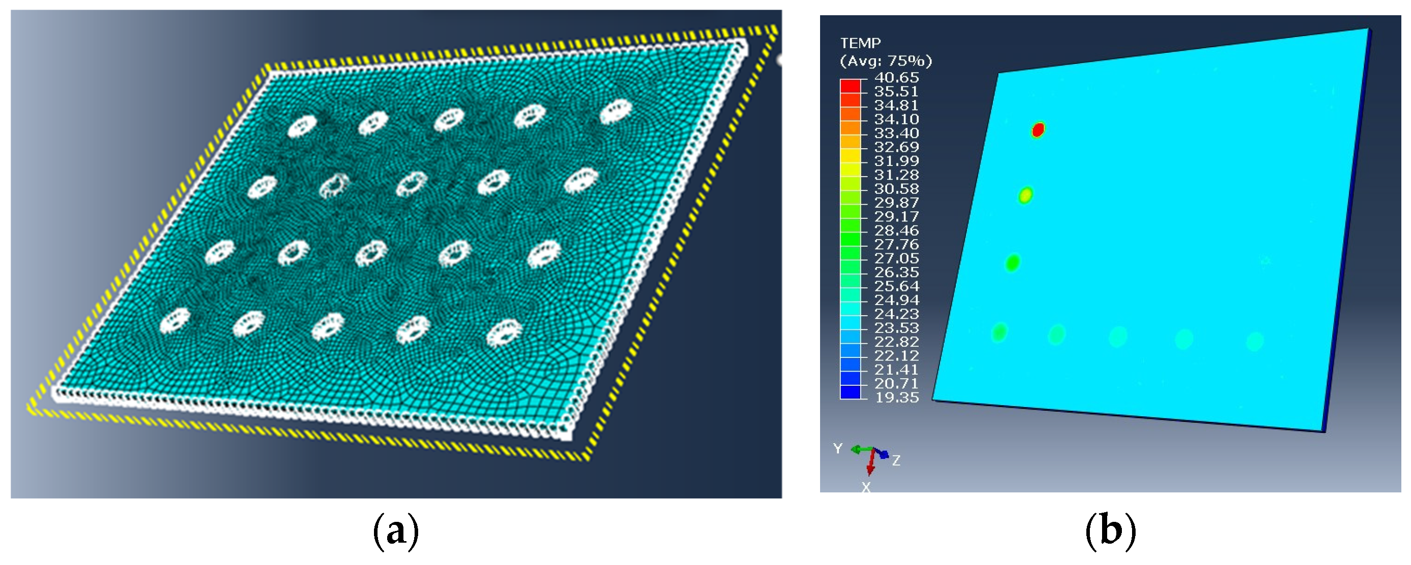
Simulation of lock-in thermography has been based on thermal FE models (FEMs) of the inspected CFRP part, with sufficient detail to represent the difference in thermal behavior at the ply level of the composite and to represent defects in the part. Verification of the simulation has been carried out on panels with intentional defects, both of increasing complexity: an isotropic HDPE panel with artificial defects of nice and regular shape (see Figure 1a) and realistic CFRP panels with realistic defects (inserts that could be left during production) of nice and regular shape. Thermal FEMs were developed in Abaqus and run on the powerful computing facility UXCS (Unix Compute Server) at NLR.
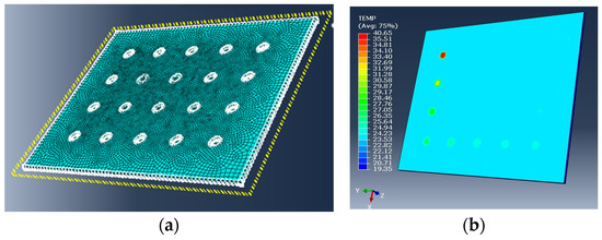
Figure 1.
(a) Fine mesh of the HDPE panel with defects (back surface); (b) Computed temperatures at the top surface of the HDPE panel.
For the HDPE panel, model parameters were obtained from the literature or estimated from the thermographic results. For the CFRP panels, the same experimental setup was used as for the HDPE panel. CFRP material parameters were used from the literature, and parameters related to the experimental setup were taken as in the model for the HDPE panel.
2.2. Simulation of Dynamic Induction Heating of Uni-Directional Thermoplastic CFRP Plates
First, an electromagnetic (EM) model is used to capture the alternating electromagnetic field around the coil, determine the inductive electrical current densities in the laminate, and determine the resulting Joule heating due to these currents. A thermal FE model of the laminate is used, in which the Joule heating is imposed as a volumetric heat load. To simulate the moving coil, the EM model has been evaluated at 16 coil positions along the weld line. An artificial neural network (ANN) has been trained using the 16 coil positions to estimate the volumetric heating for any coil position along the weld line [8]. This ANN is used in the DFLUX subroutine to provide the thermal FE model with a dynamic moving heat load.
In this paper, the dynamic inductive heating of a 608 × 101.6 mm laminate consisting of UD plies of Toray Cetex® TC1225 LMPAEK/T700 with a [0,90]3,s layup has been modeled. Experiments have been performed with the same material where a copper coil with an applied current of 302.4 A and frequency of 280 Hz is moved over the centerline of the laminate (in the middle of the short direction) with speed of 3.3 mm/s at a height of 11 mm. An infrared camera has been used to capture the temperature evolution during the weld for verification of the dynamic inductive heating simulations.
2.3. Simulation of Fan Blades for Wind Tunnel Testing
For the design and analysis of the composite fan blade, a detailed FE modeling approach has been developed, taking into account accurately the 3D blade geometry, including blade foot, composite material properties, fiber directions, and composite layup, including verification on representative 3D test samples [9]. Blade hot-to-cold analysis at the aerodynamic design point ADP-S1 has been applied to retrieve the blade’s cold shape that is to be manufactured. With the cold shape, the hot shapes were calculated for 9 different load cases. A blade shell FEM with approximate foot geometry, with fixed boundary conditions (BC), has been used to check the blade twist angles and blade tip clearance gap size for all operational load cases. A blade shell FEM with detailed, as-made foot, with contact analysis (CNT), has been used to assess the strength of the blade and its dynamic behavior under operational conditions.
Further validation of the FEMs has been carried out on manufactured test blades. A tap test has been carried out to assess the first three eigenfrequencies. In addition, static combined load tests have been performed with three test blades loaded with a force in the span direction representing the centrifugal load and a lateral force representing the aerodynamic load. The optimal orientation for the blade in the combined load test setup has been determined by the FE simulation to match the strain distribution for wind tunnel load case Maximum Flow Capacity (MFC-LLF) as good as possible, which has the largest aerodynamic load and an exceptionally large centrifugal load.
3. Results
3.1. Simulation of Lock-In Thermography
A mesh sensitivity study on the HDPE panel led to a fine mesh with linear hexahedral elements of type DC3D8, requiring 25 h of computation for analyzing the entire panel with various defects, see Figure 1. Further analyses were focused on one defect with a surrounding piece of pristine material.
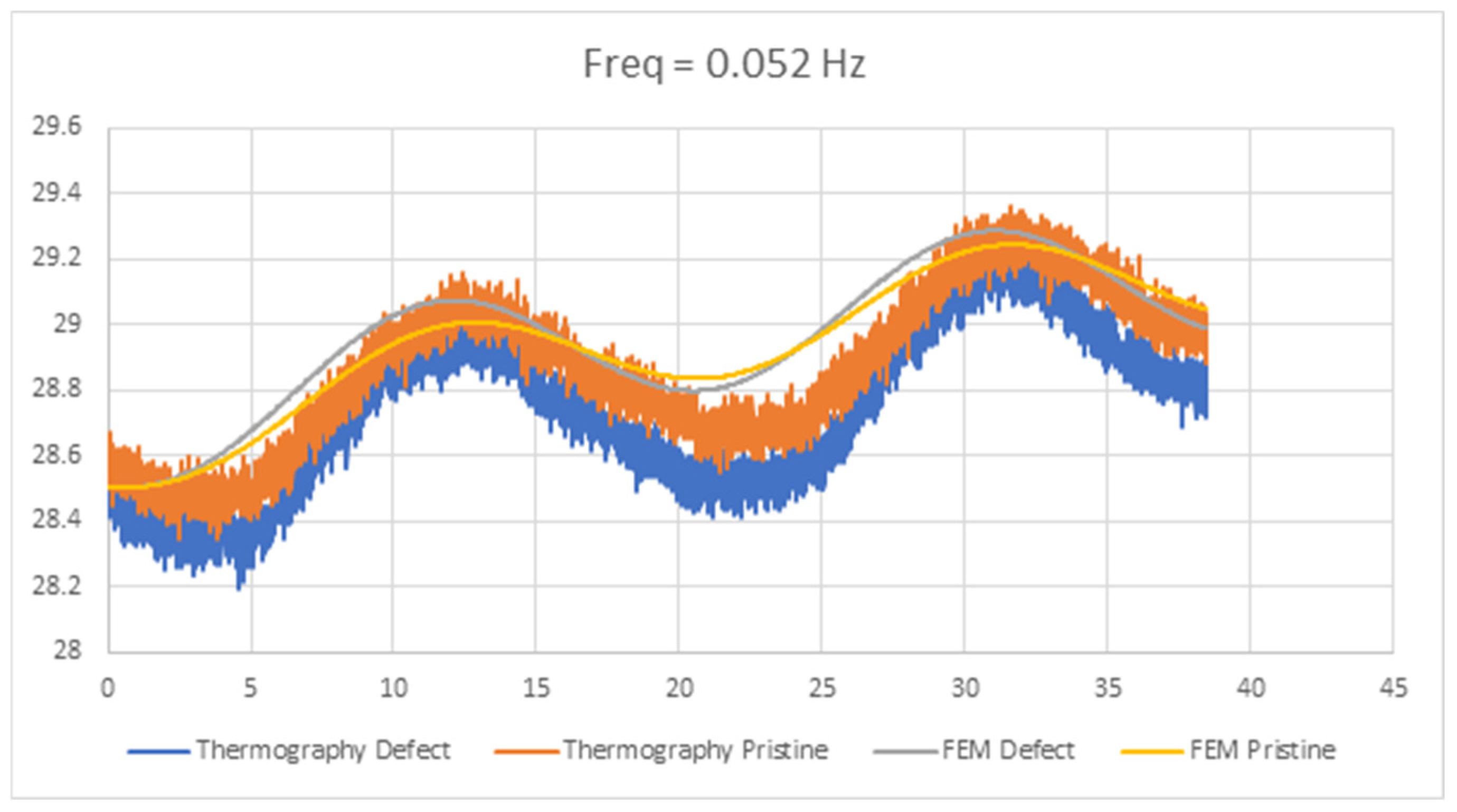
The difference in thermal behavior between a pixel in the pristine material and a pixel in the defect material has been compared; see Figure 2.
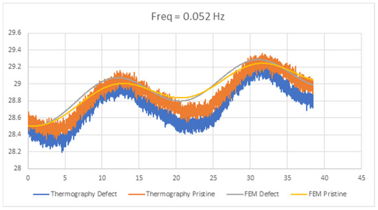
Figure 2.
Comparison of thermal behavior (temperature against time) at the surface of the CFRP panel above pristine material and above defect, as computed by thermal FEM and as measured by lock-in thermography, with heat source frequency 0.052 Hz.
The phase difference in the thermal behavior between the pixel above the pristine material and the pixel above the defect is relevant for defect detection. In the case of Figure 2, based on two acquisition cycles, this phase difference is 5 degrees according to the measurement and 10 degrees according to the thermal FEM. It is concluded that the difference in thermal behavior between defect and pristine material is sufficiently represented in the simulation.
3.2. Simulation of Dynamic Induction Heating
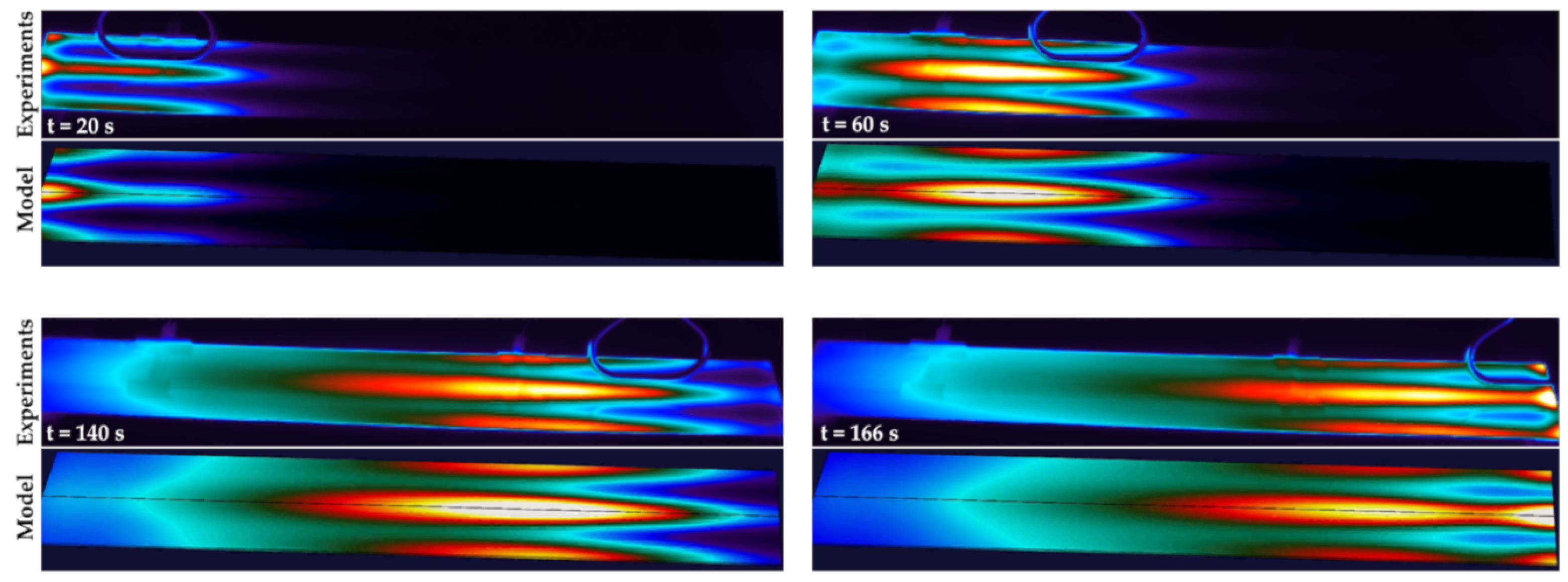
Figure 3 displays snapshots of the infrared (IR) camera images taken in an experiment of inductive heating of the CFRP laminate with the coil moving from left to right. Per snapshot, the model results are displayed for comparison. At t = 20 s, the measured temperature is high in the left edge region. The model also captures this edge effect; however, the temperature rises too much, and the edge effect is not localized as in the experiment. From the simulation results, it is seen that the current density is large at the edge, as eddy currents are squeezed there. This causes high Joule heating, which explains the increase in temperature. At t = 60 s and t = 140 s, the location of the peak temperature in the experiment is just behind the coil, which is captured well in the model. Furthermore, an increase in temperature along the parallel edges is observed both experimentally and in the model. At t = 166 s, the coil is near the right edge. Again, significant heating occurs at the right edge, both in the experiment and the model, with some local overprediction in the model.
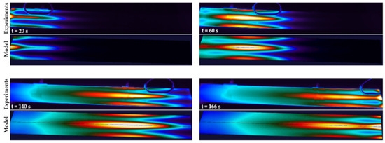
Figure 3.
Snapshots of IR camera images taken at time instants 20, 60, 140, and 166 sec during the inductive heating of a thermoplastic CFRP laminate, compared to the same snapshots obtained from the inductive heating model.
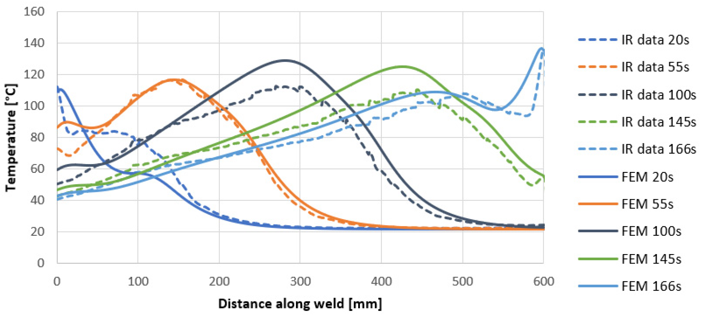
Figure 4 displays temperature profiles along the center line of the laminate at different moments during the dynamic induction heating process. The FEM and the experimental results can be compared more quantitatively. In the middle of the process, the FEM and experimental profiles match relatively well, with a difference in peak temperature < 20 °C. Near the edges, the FEM result deviates more from the experiment at the beginning (t = 20 s) and at the end (t = 166 s) of the process.
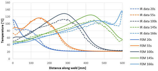
Figure 4.
Temperature profile along the center line of the laminate at different time points during the inductive heating process comparing IR camera data with FEM predictions.
3.3. Simulation of Fan Blades for Wind Tunnel Testing
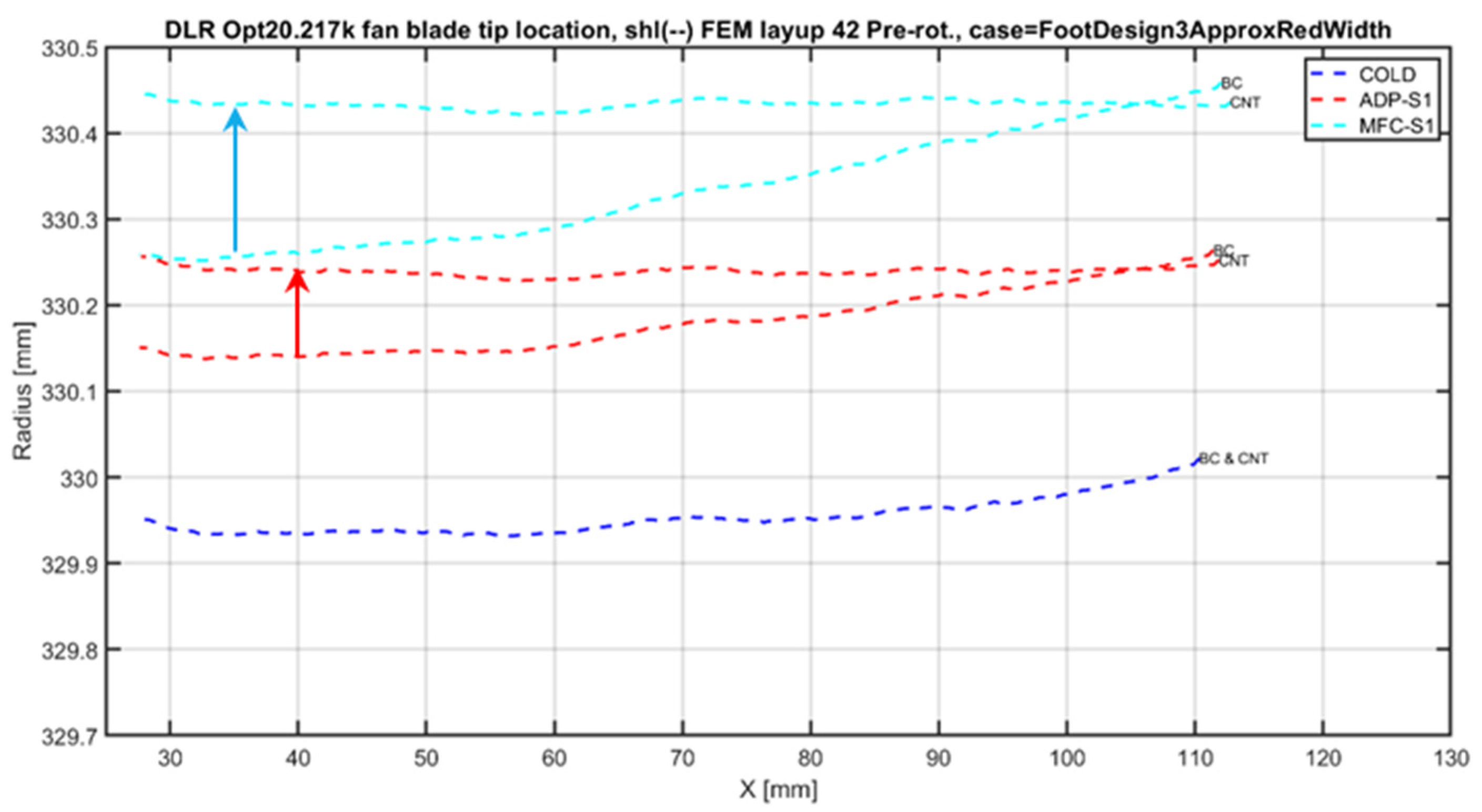
According to both the blade FEM with the approximated foot geometry, with fixed boundary condition and the blade FEM with detailed solid foot, with contact analysis, the largest tip radius occurs in load case MFC-S1, which has the largest centrifugal load, resulting in the smallest tip gap with the fan casing (see Figure 5). The MFC-S1 load also gave the smallest safety factors on fiber and matrix failure criteria in the blade strength assessment.
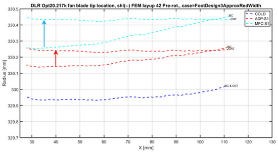
Figure 5.
Blade tip radius as a function of chord location for approximate foot geometry with fixed boundary condition (BC) and for detailed foot with contact analysis (CNT).
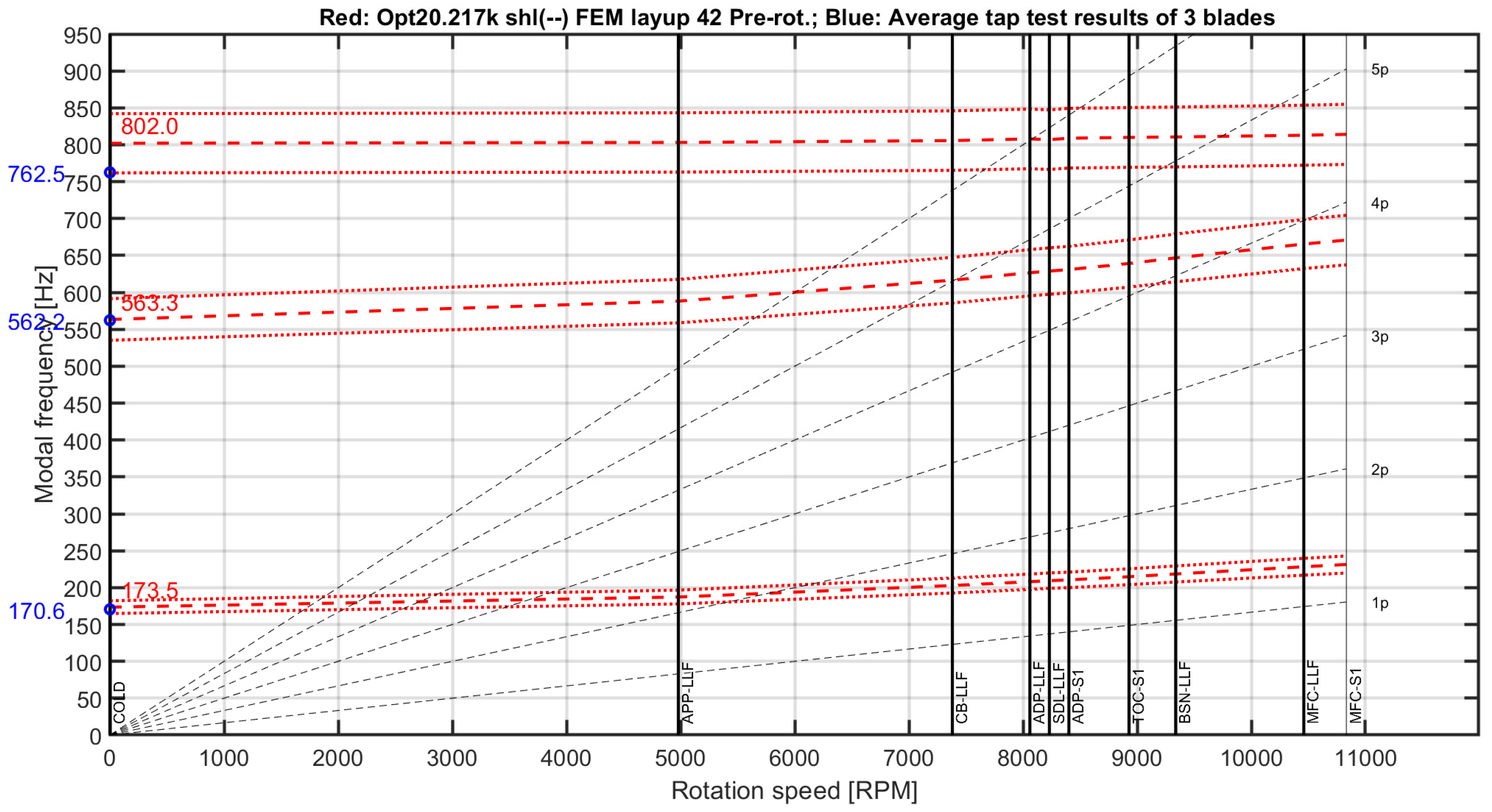
Figure 6 shows the Campbell diagram of the dynamic behavior under operational conditions. The first two bending eigenfrequencies at zero rotational speed predicted by the blade model with detailed foot agree very well with experimental tap test results (within 1.72%); only the first torsion eigenfrequency is overpredicted by 5.18%. Failure initiation in the combined load tests for all test blades took place at much higher combined loads than will be seen by the blades during the wind tunnel test campaign.
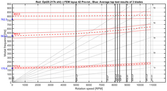
Figure 6.
Campbell diagram for shell blade FEM with detailed solid foot, based on 9 load cases, and with FEM (red) and average tap test results (blue) at zero rotational speed.
4. Discussion
4.1. Simulation of Lock-In Thermography
With the successful simulation, training data for AI can be generated. Various defects could be simulated beyond the defects simulated in the present paper, including delamination and voids. Furthermore, design features also need to be simulated to be visible in thermographic scans, such as differences in thickness.
Further considerations may be given to increase the accuracy of the model. Thermographic time plots suggest some high-frequency behavior currently not covered by the simulation, see Figure 2, in which the heat is generated precisely in accordance with the specified frequency. Modeling of the heat source, as in [6], may contribute to including this high-frequency behavior in the simulation. As an alternative, filtering this high-frequency behavior before applying AI could also be considered.
Furthermore, the simulation capability can also be used for optimizing lock-in thermography (e.g., frequency, amplitude, intensity of the lamps, number of acquisition and conditioning cycles) and for further understanding the range of applications for lock-in thermography (e.g., in terms of panel thickness). Finally, it is expected that this thermal FEM approach can also be used to model other thermographic methods, such as long pulse thermography and transmission thermography, which were applied in [2].
4.2. Simulation of Dynamic Induction Heating
The FEM developed for the simulation of dynamic induction heating of thermoplastic CFRP laminates gives qualitatively good results. The trends in temperature increase and decrease observed near the laminate edge and just behind the moving coil are predicted well by the numerical model. However, the numerical model shows significant deviation from the experimental results when the coil is near one of the edges perpendicular to the coil movement. Further investigation is required into the modeling of the coil when it is located near the edge. The current EM model has been developed using a static coil in the center of a laminate, far away from the perpendicular edge. Using static experiments with the coil positioned near the edge would give more information on the accuracy of the EM model for these coil positions. Furthermore, it could be the case that the ANN implemented for the dynamic simulation requires more data points on coil positions close to the perpendicular edges.
4.3. Simulation of Fan Blades for Wind Tunnel Testing
The blade tip radius at the leading edge for load case MFC-S1 simulated with contact analysis is larger compared to those simulated with fixed boundary conditions; see the arrows in Figure 6. This is due to the blade foot slip in the hub, causing the leading edge to move upwards in a span direction. Safety factors on fiber breakage (factor 2.2) and interlaminar shear matrix cracking (factor 2.2) have been found in the blade strength assessment with detailed solid foot for load case MFC-S1 without dynamic allowance. These safety factors are considered sufficient. The predicted separation distance between the first torsion eigenfrequency and second bending eigenfrequency is larger than 21% over the whole operational speed range, which is more than the required 10%. Also, no crossings are foreseen for the first three modes, with engine orders one to five at operational rotational speeds. Only one near crossing with engine order five for the CutBack load case (CB-LLF) is predicted. In the combined load tests, the test blades still took up load after failure initiation, which gives confidence that the blades will not fail in the intended tests. Experimental failure initiation took place at the high-stress location predicted by FE analysis, which gives confidence in the developed blade detailed FE modeling approach.
5. Conclusions
Thermoplastic composite aircraft contribute to sustainability by enabling lower weight, efficient integration by welding, and better recyclability than thermosets. Instrumented composite fans for wind tunnel models enable accurate, representative, and safe testing of fuel-saving UHBR propulsion concepts. These composite parts studied in their context show the need to simulate phenomena taking place at or below the 1 mm scale, involving multiple systems and/or multiple disciplines. Appropriate combinations of modeling methods are needed for the development of the simulation capability and for early design or conceptual studies while mastering computational complexity. Step-wise validation against experiments is needed to verify modeling accuracy. Depending on the application, further work is needed to increase local model accuracy.
Supplementary Materials
Supplementary material can be found in [8,9]. https://doi.org/10.60691/yj56-np80, access date 10 March 2025; https://www.icas.org/ICAS_ARCHIVE/ICAS2024/data/papers/ICAS2024_0157_paper.pdf, acccess date 10 March 2025
Author Contributions
Conceptualization, J.K., T.K., and B.N.; methodology, J.K., M.M., T.K., B.N., O.E., and R.N.; software, M.M., T.K., and B.N.; validation, J.K., M.M., T.K., and B.N.; formal analysis, M.M., T.K., and B.N.; investigation, M.M., T.K., B.N., O.E., and R.N.; resources, J.K., O.E., and R.N.; data curation, M.M., T.K., and B.N.; writing—original draft preparation, J.K., M.M., T.K., and B.N.; writing—review and editing, J.K., M.M., T.K., B.N., O.E., and R.N.; visualization, M.M., T.K., and B.N.; supervision, J.K.; project administration, J.K.; funding acquisition, J.K. All authors have read and agreed to the published version of the manuscript.
Funding
This research was funded by the Clean Sky 2 Joint Undertaking and the European Commission under the European Union’s Horizon 2020 research and innovation programme under grant agreements Nos 807097, 945583, 680954, 958303 and by the Dutch Ministry of Economic Affairs and Climate in the RDM Mobility Fund programme “Thermoplastics for a sustainable aviation”.
Institutional Review Board Statement
Not applicable.
Informed Consent Statement
Not applicable.
Data Availability Statement
Data are contained within the article or Supplementary Materials.
Conflicts of Interest
The authors declare no conflicts of interest.
References
- Roth, Y.C.; Herrmann, R.; Sanchez Santos, C.; Uellendahl, M.; Koopman, J.; Henneberg, A.; Kos, J.; Villegas, I.F.; Choudhary, A.; Larsen, L.; et al. CleanSky2/Clean Aviation Large Passenger Aircraft for more sustainable commercial fuselage technologies—Major achievements. In Proceedings of the 34th Congress of the International Council of the Aeronautical Sciences, Firenze, Italy, 9–13 September 2024; Available online: https://www.icas.org/ICAS_ARCHIVE/ICAS2024/data/preview/ICAS2024_0091.htm (accessed on 10 March 2025).
- Deutz, D.B.; Bosch, A.F.; Baptista, D.E.; van Veen, E.S.; Platenkamp, D.J.; Jansen, H.P. Non-contact NDT methods for large-scale CFRP aircraft parts. In Proceedings of the 14th EASN International Conference on “Innovation in Aviation & Space towards Sustainability Today & Tomorrow”, Thessaloniki, Greece, 8–11 October 2024. [Google Scholar]
- Clean Aviation Joint Undertaking, Movie: The SA2FIR Test Rig—Optimizing Greener Engine Integration!. Clean Aviation Joint Undertaking. 2021. Available online: https://www.youtube.com/watch?v=C56OSgpTwYo (accessed on 10 March 2025).
- Lopez, F.; Paulo Nicolau N de Ibarra-Castanedo, C.; Maldague, X. Thermal–numerical model and computational simulation of pulsed thermography inspection of carbon fiber-reinforced composites. Int. J. Therm. Sci. 2014, 86, 325–340. [Google Scholar] [CrossRef]
- Coelho Fernandez, H.; Zang, H.; Figueiredo, A.; Ibarra-Castanedo, C. Carbon fiber composite inspection and defect characterization using active infrared thermography: Numerical simulations and experimental results. Appl. Opt. 2016, 55, 46–53. [Google Scholar] [CrossRef] [PubMed]
- Notebaert, A.; Quinten, J.; Moonens, M.; Olez, V.; Barros, C.; Simões Cunha, S., Jr.; Demarbaix, A. Numerical Modelling of the Heat Source and the Thermal Response of an Additively Manufactured Composite during an Active Thermographic Inspection. Materials 2024, 17, 13. [Google Scholar] [CrossRef] [PubMed]
- Vankan, W.J.; van Hoorn, N.; de Wit, A.J.; Koenis, T.P.A. Electromagnetic induction heating of TP-CFRP laminates: FEM modelling and validation. In Proceedings of the 34th Congress of the Int. Council of the Aeronautical Sciences, Firenze, Italy, 9–13 September 2024; Available online: https://www.icas.org/ICAS_ARCHIVE/ICAS2024/data/preview/ICAS2024_0032.htm (accessed on 10 March 2025).
- Koenis, T.P.A.; de Wit, A.J.; Maas, R.; van Hoorn, N. A machine learning approach to dynamic simulation of electromagnetic heating. In Proceedings of the 21st European Conference on Composite Materials, Nantes, France, 2–5 July 2024; The European Society for Composite Materials (ESCM) and the Ecole Centrale de Nantes: Nantes, France, 2024; Volume 5, pp. 548–555. [Google Scholar] [CrossRef]
- Noordman, B.A.T.; Vankan, W.J. Design and analysis of a scaled composite UHBR fan blade for wind tunnel tests. In Proceedings of the 34th Congress of the Int. Council of the Aeronautical Sciences, Firenze, Italy, 9–13 September 2024; pp. 1–11. Available online: https://www.icas.org/ICAS_ARCHIVE/ICAS2024/data/papers/ICAS2024_0157_paper.pdf (accessed on 10 March 2025), ISSN 2958-4647.
Disclaimer/Publisher’s Note: The statements, opinions and data contained in all publications are solely those of the individual author(s) and contributor(s) and not of MDPI and/or the editor(s). MDPI and/or the editor(s) disclaim responsibility for any injury to people or property resulting from any ideas, methods, instructions or products referred to in the content. |
© 2025 by the authors. Licensee MDPI, Basel, Switzerland. This article is an open access article distributed under the terms and conditions of the Creative Commons Attribution (CC BY) license (https://creativecommons.org/licenses/by/4.0/).