Abstract
The prospect of GNSS meta-signal tracking promises the synergy of both code reliability and the high precision of sub-carrier observations. The latter has the advantage, in comparison to carrier-phase observations, of having wavelengths in the order of a few meters instead of cm-level. This realizes the possibility of resolving sub-carrier-phase ambiguities without the need for a reference station providing positioning solutions with a sub-meter level of accuracy. In the frame of the HANDS-CD project led by IGASPIN GmbH, a synthetic meta-signal observation formed from Galileo E5a and E5b signals using the widelaning concept will be demonstrated in this contribution. This analysis is performed based on a simulated kinematic trajectory. The synthetic meta-signal observations are fed into an extended Kalman filter-based positioning engine called the meta-signal positioning engine (M-SiPE-tool), which applies the least-squares ambiguity decorrelation adjustment (LAMBDA) ambiguity fixing method to resolve the sub-carrier ambiguities. To assess the robustness of the positioning filter against signal impairments, the observations of many Galileo satellites are synthetically contaminated by multipath reflection with different amplitudes. The outcome of the positioning engine exhibits successful sub-carrier ambiguity fixing and provides a sub-decimeter positioning accuracy for a code multipath amplitude of less than 30 m, or for a sub-carrier multipath amplitude of less than 0.5 m.
1. Introduction
The need for more robust signals for positioning in harsh environments such as urban canyons has become increasingly important over the last decades. Low-cost global navigation satellite system (GNSS) chips are nowadays present in smartphones, progressively with more than one frequency, enabling high-accuracy positioning, especially when carrier-phase observations are available and utilized properly. This is attractive for applications such as autonomous driving, location-based service (LBS), or even for cost-efficient unmanned aerial vehicles (UAVs), which require robustness due to receiver dynamics as well as when signal interference such as signal jamming is present. Without the need for complementary sensors such as inertial measurement units (IMUs) or vision sensors, combining two signal components and processing them as a single entity yields a more accurate and robust signal that benefits from both code robustness and carrier-phase accuracy. Such a type of technique is called a meta-signal.
A large variety of techniques exist to process meta-signals, including wideband processing or using dedicated sub-carrier loops. As an important milestone, Refs. [1,2] have shown that sub-carrier-phase observations are, under certain assumptions, equivalent to the wide-lane linear combination of the carrier-phase measurements obtained from the two original side-band components. This means the meta-signal is equivalent to the wide-lane linear combination of the carrier-phase measurements obtained from two independently processed signals. Taking these findings into account, it is possible to emulate meta-signal processing by using the wide-lane technique. Therefore, the potential of such a signal can be explored directly on the observation level while avoiding the high-complex signal processing stage in the GNSS receiver. Nevertheless, the focus in [1,2] was dedicated more to the signal processing side, where the positioning performance was evaluated by a simple single-point positioning (SPP) in a static case under optimal signal conditions. That means that the challenge faced by the (sub-)carrier observations, such as multipath or other signal impairments, was not taken into consideration as (sub-)carrier measurements were not used by the positioning engine. This means that the effects of the (sub-)carrier cycle slips have not yet been studied, and therefore, the ambiguity resolution performance in meta-signals has not been analyzed. The most reliable technique for the carrier-phase ambiguity resolution is the LAMBDA method [3], which we adapt in this contribution to solve the sub-carrier ambiguities (as already demonstrated for the first time in [4]) for different situations, i.e., static and kinematic, with/without signal impairments. Here, the focus will be only on the Galileo E5a-E5b observations, which can be made available by the receiver-independent exchange format (RINEX) from any GNSS-receiver/antenna combination that allows the reception of those signals.
This paper is structured as follows: First, the concept of meta-signal tracking and the derivation of the observables employed for positioning are briefly introduced. In the second section, an overview about our extended Kalman filter (EKF)-based positioning engine, M-SiPE-tool, which processes both the meta-signal pseudorange and sub-carrier observation, will be given. Afterwards, the performance of this engine for various multipath scenarios will be presented and analyzed, based on a simulated kinematic car trajectory. The last section concludes the paper by providing a short summary and conclusions.
2. Generation of Meta-Signal Observables
The generated meta-signal observations correspond to the E5a-E5b meta-signal as described in [1] by using the narrow- and wide-lane techniques. These techniques employ the pseudorange and carrier-phase information of the narrowband processing output of the Galileo E5a and E5b signals to generate the meta-signal carrier-phase, meta-signal sub-carrier-phase, and meta-signal pseudorange observations.
The meta-signal carrier-phase observation, , is computed by applying the narrow-lane carrier-phase combination of the processed side-band carrier-phase observations, i.e.,
where and are the carrier-phase measurement, in meters, and the wavelength of the side-band signal i, respectively. It must be noted that the expression above, is provided in cycles. The meta-signal sub-carrier-phase estimation is performed by applying the wide-lane combination of the processed side-band carrier-phase observations,
where is the center frequency of the i-th side-band signal.
Finally, the pseudorange computation of the meta-signal can be approached by combining the pseudorange observations of each side-band signal. However, each pseudorange must be multiplied by a factor that depends on the side-band signal amplitude, , and the slope, , of its auto-correlation function (ACF). Taking this into consideration, the meta-signal pseudorange, , can be computed by means of the following expression:
Considering that the signals involved are the E5a and E5b signals, which present the same power allocation and the ACF slope, a simple average between the side-band signal pseudorange observations is applied to achieve the meta-signal pseudorange.
The single point positioning (SPP) comparison between the described Galileo E5a+E5b meta-signal approach and the Galileo E5 AltBOC is also provided in [1]. In the next section, our advanced positioning engine employed to enhance the meta-signal performance is described.
3. Kalman Filter-Based Meta-Signal Positioning Engine
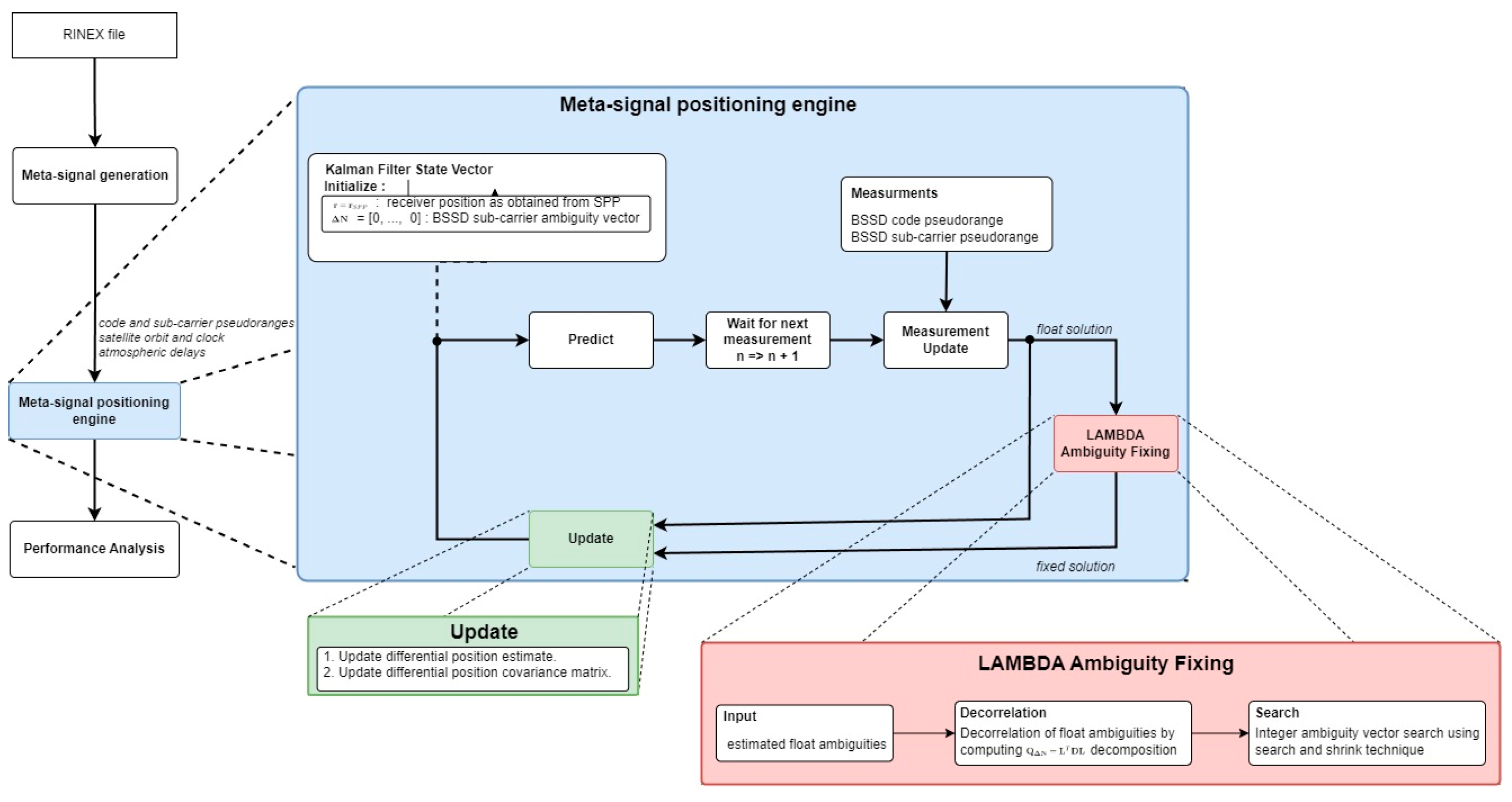
In the M-SiPE engine, as depicted in Figure 1, a closed-loop Kalman filter is employed. This filter utilizes code pseudorange and sub-carrier measurements obtained from a RINEX observation file at each epoch to update its state vector. The resulting float solution from the filter state vector is subsequently fed into a specialized LAMBDA ambiguity resolution block. This block carries out sub-carrier ambiguity resolution, generating a fixed solution that is conditionally utilized to update the estimated receiver position. Since the employed meta-signal observations can be seen as a single-frequency approach, where in addition the ambiguities have to be solved, we applied the approach of using the between single satellite difference (BSSD). There, the satellite with the highest elevation is fixed as a reference from which the BSSD of the other visible satellites can be estimated.
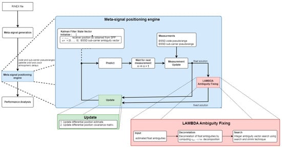
Figure 1.
Meta-signal positioning engine (M-SiPE), adapted from reference [5].
The sub-carrier phase observations are inherently ambiguous, with an ambiguity represented by integer multiples of the sub-carrier wavelength. This ambiguity is effectively resolved in the positioning domain through the LAMBDA ambiguity-fixing method. In this study, we utilize the LAMBDA software package, originally developed at TU Delft [6], for implementation.
In the standard LAMBDA method implementation, float ambiguities are initially decorrelated using Cholesky decomposition and Z-transformation to reparametrize the float ambiguities vector and its covariance matrix. After the float ambiguity vector and covariance matrix are decorrelated, a mapping function is used to obtain the integer-valued estimate. The integer estimate is determined through an integer search over a hyper-ellipsoid scaled by a constant and shaped by the ambiguities covariance matrix. Following completion of the search process, the fixed ambiguity vector is obtained by inverse Z-transform of the searched solution. Within this filter implementation, the back-transformed integer candidate vectors are utilized for constructing the ambiguity-fixing ratio and difference metrics. The ratio and difference are then compared against their respective thresholds. Whenever these thresholds are exceeded, a fixed solution update step is performed.
Considering the correct resolution of these fixed ambiguities, the accuracy of the position error solution should be at the order of the sub-carrier noise measurement. Leveraging the low measurement noise associated with sub-carrier observations, substantial enhancement in position accuracy can be obtained.
4. Positioning Performance: Results and Analysis
4.1. Processing Toolchain
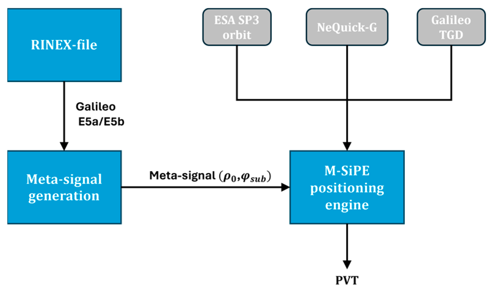
To formulate meta-signal measurements, pseudorange and carrier phase observations are obtained from a RINEX file for both Galileo E5a and E5b, as described in Section 2. In the second step, the needed meta-signal observables, and (in cycles), are computed, which are introduced later on to the M-SiPE, which attempts to solve the sub-carrier ambiguities using the LAMBDA technique [6], where the associated MATLAB-based tool, as described in [7], has been appended to the KF-frame to decorrelate the estimated float BSSD-ambiguities. If this step can be conducted successfully, sub-decimeter level accuracy can be obtained. To achieve this level of accuracy, various corrections, such as satellite orbits and atmospheric models, have to be considered when processing the observations. During the implementation and tuning of the M-SiPE, we figured out that the employed ionospheric model plays the key role in enabling robust fixing of the sub-carrier ambiguities from the E5a-E5b sideband component. For this reason, we applied the Galileo single-frequency ionospheric correction algorithm (NeQuick G), which is realized by an official source code published by the European Commission [8]. Figure 2 summarizes all the above-mentioned steps developed to combine both the wide-lane technique and the LAMBDA method to provide reliable navigation information.

Figure 2.
Employed processing toolchain to evaluate meta-signal observations.
4.2. Description of the Simulated Cases
In order to assess the robustness of the M-SiPE tool against external signal impairments, such as multipath, various simulation scenarios have been generated. There, the multipath error is incorporated into the Galileo E5a and E5b pseudorange and carrier phase, respectively, utilizing the following simplified model:
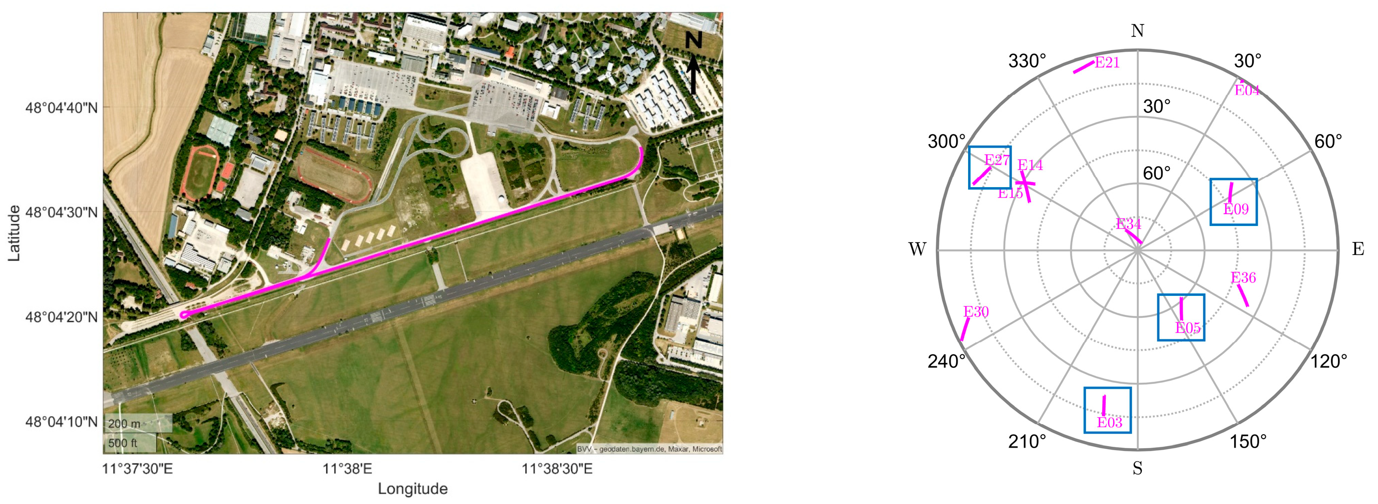
where A is the amplitude of the signal and f is the frequency. In comparison to stochastic multipath models like [9], we find the use of this simpler deterministic model better to quantify the limit of multipath that the M-SiPE tool can deal with by successfully resolving the ambiguity. The main simulation framework is realized on the RINEX level, where a trajectory/static coordinate is given as ground truth (see Figure 3) to build the GNSS observables for a specific GPS time, where the same error sources (ionospheric and tropospheric models) have been used as applied in the positioning. Before adding the multipath signal, we assumed that the simulated observables were contaminated by only additive white Gaussian noise (AWGN).

Figure 3.
Ground track of reference trajectory for the simulations. On the right side, the skyplot of the visible Galileo satellites is depicted, where the blue boxes indicate the contaminated satellites.
In the simulations, this model was integrated into the signals starting from the 60th second onwards. The multipath model was chosen to be slow-varying, i.e., 0.01 Hz, while the amplitude value was incrementally increased to examine the effects on the positioning solution. This was applied for both code and sub-carrier observations separately. As highlighted by the blue boxes in the skyplot (see Figure 3), we contaminated 4 satellites from 11 visible Galileo satellites, i.e., E03, E05, E09, and E27, by multipath.
In general, the simulated scenarios can be split into the following three main cases:
- In the first case (see Section 4.2.1), both code and sub-carrier observations were contaminated by this signal disturbance equally, where the amplitude values of 0.75 m, 1 m, 1.5 m, 1.75 m, and 2 m were considered.
- In the second scenario block (see Section 4.2.1), the multipath amplitude in the sub-carrier signal was fixed to a quarter of the wavelength, while allowing the code values to be 2 m, 4 m, 8 m, and 16 m.
- In the last test cases, zero code-multipath was set up while increasing the amplitude on the sub-carrier observations linearly, i.e., 0.24 m increments, until 2.4 m. On the other hand, the opposite strategy was applied to the code observations, where this time no multipath error was injected into the sub-carrier observation, but the amplitude of the code-multipath was enlarged in 10 m steps until it attained 100 m amplitude. The results are summarized in Section 4.2.2.
4.2.1. Simulation with Different Sub-Carrier and Code Multipath Disturbance
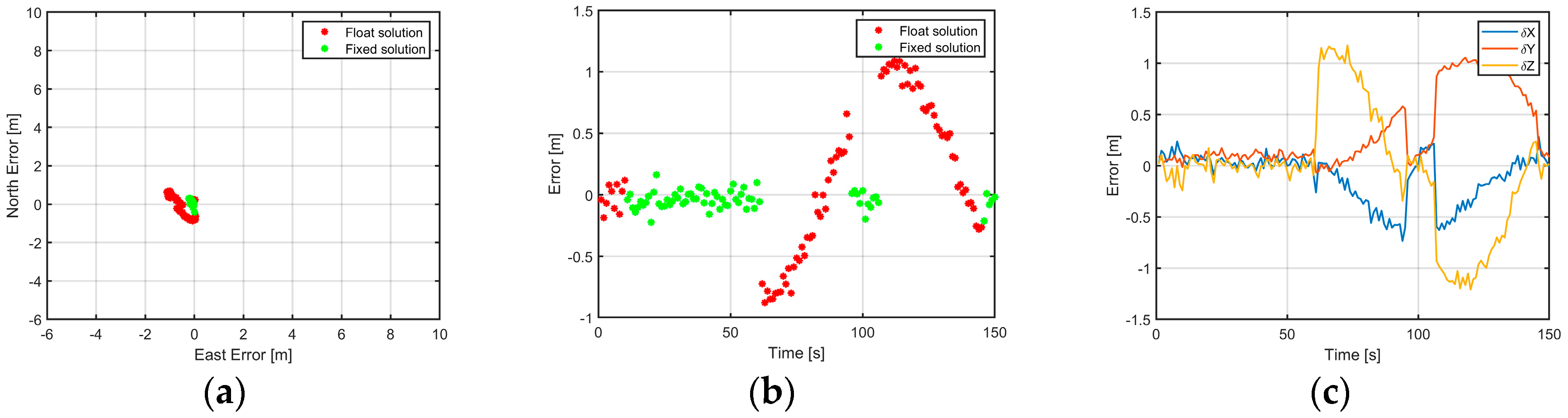
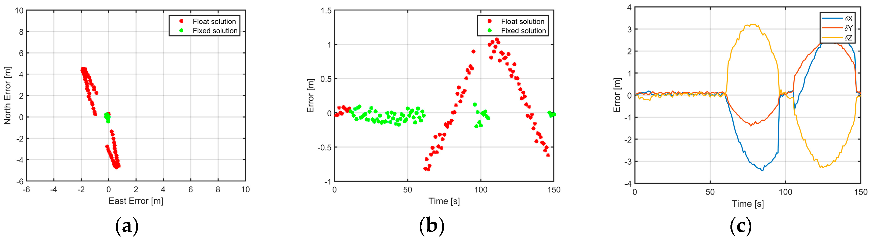
In the figures, i.e., Figure 4, Figure 5, Figure 6 and Figure 7, only the results with the minimum and the maximum employed multi-path error, i.e., 0.75 m and 2 m (see general description in the previous paragraph), are visualized for the first simulation case. Besides the convergence time of the M-SiPE algorithm in the first 10 s, where only the float solution is available, our technique is able to suppress the multipath effect applied on both meta-signal observables. This is especially true when the multipath error amplitude is negative, i.e., is going down to −0.75 m. However, when applying an amplitude of 2 m, the M-SiPE tool seems to obtain some wrong fixed epochs at around 100 s. At the end of the scenario, between 140 and 150 s, the algorithm is able to recover and resolve the sub-carrier ambiguity term. In Figure 4b, it is also interesting to see a smooth transition between the float and fixing area.
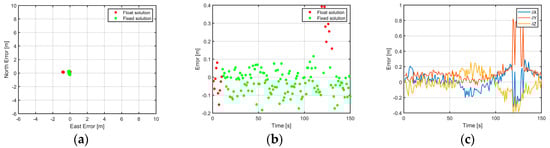
Figure 4.
Positioning results with code and sub-carrier multipath amplitude of both equal to 0.75 m: (a) horizontal position error; (b) vertical position error; (c) position error in ECEF frame.
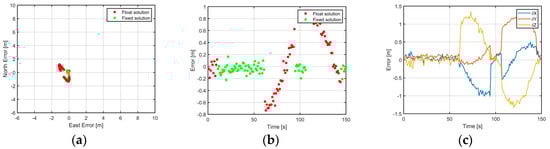
Figure 5.
Positioning results with code and sub-carrier multipath amplitude of both equal to 2.00 m: (a) horizontal position error; (b) vertical position error; (c) position error in ECEF frame.
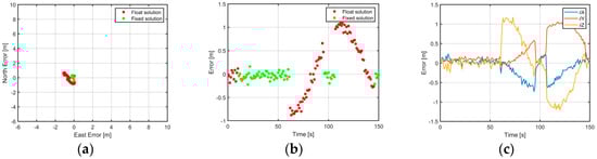
Figure 6.
Positioning results with a sub-carrier multipath amplitude of 2.40 m and a code multipath amplitude of 2 m: (a) horizontal position error; (b) vertical position error; (c) position error in ECEF frame.

Figure 7.
Positioning results with a sub-carrier multipath amplitude of 2.40 m and a code multipath amplitude of 16 m: (a) horizontal position error; (b) vertical position error; (c) position error in ECEF frame.
The statistics, such as the root mean square (RMS) of the position error, from the other scenarios with the values in between, are summarized in Table 1, Table 2 and Table 3. The associated five scenarios are indicated by the sub-script used to denote the different errors. In the tables, the error sub-script ranges from 1 to 9. The five cases just described are associated with sub-scripts from 1 to 5.

Table 1.
Statistics for position error in the east axis for all simulations.
Table 2.
Statistics for position error in the north axis for all simulations.
Table 3.
Statistics for position error in the up axis for all simulations.
In the remaining simulations numbered from 6 to 9 (see Table 1, Table 2 and Table 3), the multipath amplitude of the sub-carrier phase is fixed at 2.4 m while the code values are 2 m, 4 m, 8 m, and 16 m. The main reason for applying this constant multipath amplitude to the sub-carrier observations is that multipath errors are limited by a quarter of the wavelength of the signal () for carrier-phase observations [10]. In our case, this corresponds to approximately 2.4 m. Similarly to the last five cases, only plots for two amplitude values, namely 2 and 16 m, are shown in Figure 6 and Figure 7. With the first test multipath amplitude, no significant change can be observed in comparison to Figure 4. But after applying a higher multipath error, i.e., 16 m, the transition between a float and fixed solution after activating the disturbance source at 60 sec becomes somehow harsh (Figure 7b). The oscillations of the sinusoidal signal can also be easily recognized in the north-east plot (Figure 7a). Therefore, the most significant error was observed in the north direction (, where an RMS value of 2.57 m and a maximum of 4.719 m (absolute value) have been achieved.
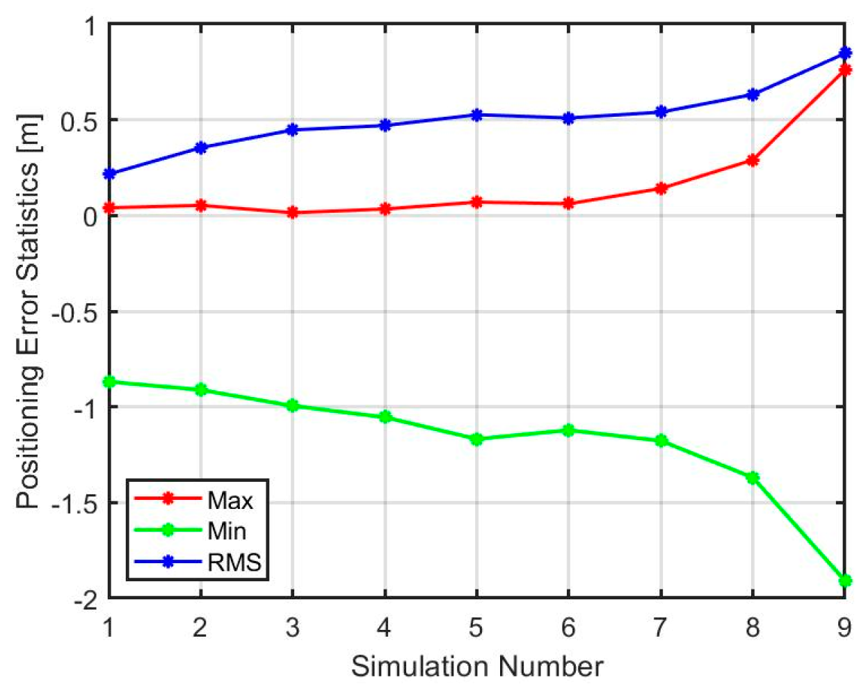
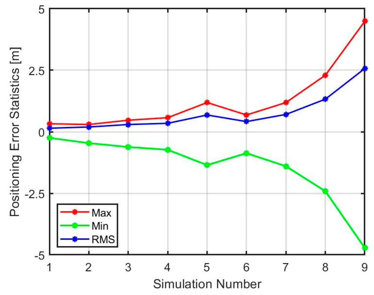
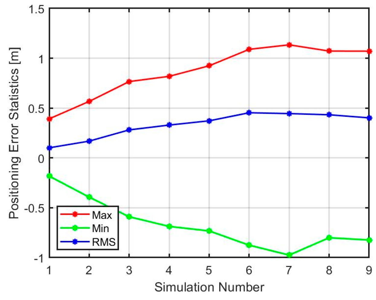
Figure 8, Figure 9 and Figure 10 summarize the statistics of all nine simulated scenarios graphically. In all these figures, it is shown that the impact of multipath on the positioning error exhibits a quadratic behavior, where the most affected axis is the north direction.
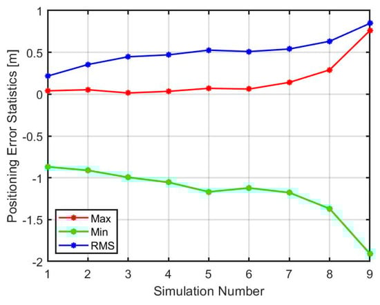
Figure 8.
Statistics for positioning error in the east direction.
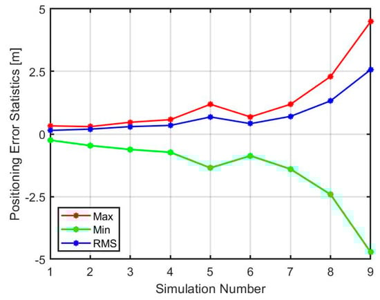
Figure 9.
Statistics for positioning error in the north direction.
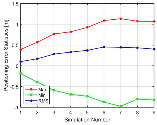
Figure 10.
Statistics for positioning error in the up direction.
4.2.2. Impact of Linear Increasing Multipath Amplitude on Sub-Carrier Ambiguity Fixing
Further examination of the multipath tolerance of the meta-signal is achieved by considering the effects of carrier and code multipath amplitude values separately. In the first set of simulations, the carrier amplitude is increased linearly from 0 to 2.4 m while keeping the code multipath to zero. Likewise, the second set of simulations is performed by increasing the code multipath linearly from 0 to 100 m and zeroing the amplitude of the multipath signal in the sub-carrier observations. In Figure 11, the results for fixing percentage as estimated by the M-SiPE tool, i.e., the integrated LAMBDA technique, are shown. The x-axis shows an increasing amplitude in the multipath model while each data point shows one simulation set up, i.e., for each applied multipath amplitude.
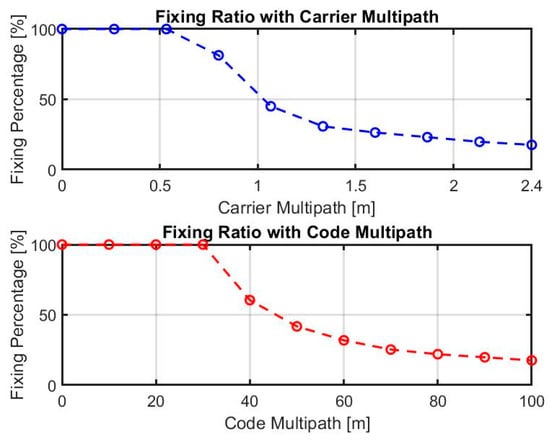
Figure 11.
Fixing ratio with increasing carrier and code multipath amplitude.
The percentage of fixing is calculated over the duration of the multipath present instances of the simulation, which starts from the 60th second onwards. The multipath model is sinusoidal in nature (see Equation (5)), and it reaches zero near the 100th second. As a result, fixing is achieved in these instances, and the fixing percentage reaches 17% when the multipath is at its highest. It was expected that such a higher amplitude would deliver only float ambiguities, which is not the case here. The main reason for this behavior is the employed simple multipath model, where the sine wave increases to achieve the maximum, and after that, it goes towards its minimum point. When this error is near the zero-crossing area, the ambiguity-fixing procedure is successful, and position error is reduced. Alternatively, wrong fixing could also take place, which thereafter requires better tuning of the Kalman filter, i.e., choosing a higher threshold to avoid it.
5. Conclusions and Outlook
In this contribution, we demonstrated the potential of using meta-signal for positioning in harsh environments such as city urban canyons where signal reflection is inevitable. Thanks to the larger wavelength of the Galileo E5a-E5b sub-carrier signal, the employed LAMDA method allows resolving the sub-carrier ambiguity term, which leads to greater accuracy in the range of sub-decimeters, considering the single character of the used observables in the M-SiPE tool. This accuracy would not be easy to achieve if the original observation, for example, E5a/5b, were used. We observe that the multipath has no impact as long as the amplitude is less than 30 m (code) or 0.5 m (sub-carrier).
Future work may include more complex and realistic multipath simulation models such as the one described in [9]. Furthermore, the robustness and the benefit of the Beidou E1I-E1C meta-signal suggested in [11] can be explored and compared against the Galileo E5a-E5b case. It would be worthwhile to adapt this technique to mass-market low-cost devices, such as smartphones, as recently some of them (for example, the Huawei P40 Pro [12]) already provide triple-frequency Beidou signal observations, including the E1I and E1C, which would allow for a much larger sub-carrier wavelength, i.e., 20.9 m, than the one provided by the E5a-E5b meta-signal. Unfortunately, only the Galileo E5a component can be found in smartphone GNSS chips; thus, the potential of meta-signals with low-cost devices for the European satellite system cannot be currently exploited by using smartphones.
Author Contributions
Methodology, M.B., M.S.H. and M.A.-D.; software, M.B. and M.S.H.; visualization, E.K.; writing—original draft, M.B.; writing—review and editing, M.B., E.K., M.S.H., M.A.-D. and T.P.; supervision, T.P. All authors have read and agreed to the published version of the manuscript.
Funding
This research was funded by the European Space Agency with ESA Contract No. 40001737747/22/NL/CRS (Architectures for Wide-Band Meta-Signal Processing in Low-Cost Devices—HANDS CD).
Institutional Review Board Statement
Not applicable.
Informed Consent Statement
Not applicable.
Data Availability Statement
Data are available on request.
Conflicts of Interest
The authors declare no conflicts of interest.
References
- Borio, D.; Gioia, C. Reconstructing GNSS Meta-Signal Observations Using Sideband Measurements. Navig. J. Inst. Navig. 2023, 70, navi.558. [Google Scholar] [CrossRef]
- Borio, D.; Gioia; Meta-signals, C.G.N.S. Dual-Frequency Combinations and the Double Phase Estimator. In Proceedings of the 2022 International Technical Meeting of The Institute of Navigation, Long Beach, CA, USA, 25–27 January 2022. [Google Scholar]
- Teunissen, P.J.G. Least-squares estimation of the integer GPS ambiguities. In Proceedings of the Invited Lecture, Section IV Theory and Methodology, IAG General Meeting, Beijing, China, August 1993. [Google Scholar]
- Wendel, J.; Schubert, F.M.; Hager, S. A Robust Technique for Unambiguous BOC Tracking. Navigation 2014, 61, 179–190. [Google Scholar] [CrossRef]
- Hameed, M.S.; Woerz, T.; Pany, T.; Wendel, J.; Paonni, M.; Senni, T. Demonstration of Meta-signal Positioning using LAMBDA Ambiguity Fixing Method within a Bit-true Simulation. In Proceedings of the ION GNSS+, The International Technical Meeting of the Satellite Division of The Institute of Navigation, Online, 20–24 September 2021. [Google Scholar]
- Teunissen, P.J.G. The least-squares ambiguity decorrelation adjustment: A method for fast GPS integer ambiguity estimation. J. Geod. 1995, 70, 65–82. [Google Scholar] [CrossRef]
- Verhagen, S.; Li, B.; Teunissen, P.J.G. LAMBDA—Matlab Implementation, Version 3.0; Delft University of Technology: Delft, The Netherlands; Curtin University: Bentley, WA, Australia, 2012. [Google Scholar]
- European Commission. European GNSS (Galileo) Open Service—Ionospheric Correction Algorithm for Galileo Single Frequency Users. Issue 1.2. September 2016; pp. 4–29. Available online: https://www.gsc-europa.eu/sites/default/files/sites/all/files/Galileo_Ionospheric_Model.pdf (accessed on 4 May 2024).
- Lehner, A.; Steingass, A. A Novel Channel Model for Land Mobile Satellite Navigation. In Proceedings of the ION GNSS 2005, Long Beach, CA, USA, 13–16 September 2005. [Google Scholar]
- Teunissen, P.J.G.; Montenbruck, O. Handbook of Global Navigation Satellite Systems; Springer: Cham, Switzerland, 2021. [Google Scholar]
- Borio, D.; Gioia, C. Synthetic meta-signal observations: The Beidou Case. Sensors 2024, 24, 87. [Google Scholar] [CrossRef] [PubMed]
- HUAWEI P40 Pro—Specifications. Huawei Device Co., Ltd., 2024. Available online: https://consumer.huawei.com/en/phones/p40-pro/specs/ (accessed on 4 May 2024).


Disclaimer/Publisher’s Note: The statements, opinions and data contained in all publications are solely those of the individual author(s) and contributor(s) and not of MDPI and/or the editor(s). MDPI and/or the editor(s) disclaim responsibility for any injury to people or property resulting from any ideas, methods, instructions or products referred to in the content. |
© 2025 by the authors. Licensee MDPI, Basel, Switzerland. This article is an open access article distributed under the terms and conditions of the Creative Commons Attribution (CC BY) license (https://creativecommons.org/licenses/by/4.0/).