1. Introduction and Background
Uncrewed Aerial Vehicles (UAVs), also known as drones, are increasingly being used for a variety of applications ranging from defense, search, and rescue to delivery services. Drones, when operating autonomously, typically rely on signals from the Global Navigation Satellite System (GNSS) to navigate accurately. GNSS signals, however, are sometimes interrupted and not available, especially near regions of conflict where the signals are often deliberately jammed [
1].
This problem has led to a range of alternative navigation (alt-nav) solutions to enable precision navigation in the absence of GNSS [
2]. Different alt-nav technologies have various advantages and drawbacks. Vision-based systems [
3], for example, can be low-cost but are often susceptible to inclement weather, such as rain and fog, and their performance varies with the time of day.
In this paper, a proof-of-concept Terrain-Referenced Navigation (TRN) system, suitable for small drones, is demonstrated, which employs a miniature, low-cost millimeter-wave (mm-wave) radar operating in the 60 GHz band.
2. Radar TRN
Radar TRN is a well-established GNSS-denied navigation technique [
4,
5,
6]. In fact, it was developed prior to the widespread availability of GNSS. Radar TRN involves equipping an aerial platform with a downward-facing radar, which measures the elevation profile of the ground as the platform traverses over it. By comparing the measured elevation profile to a digital terrain elevation map, the platform’s location and trajectory can be estimated.
Radar TRN offers several advantages over other alt-nav technologies. Radar, unlike optical systems, is not affected by the time of day and is much less affected by inclement weather, such as rain and fog. As TRN radars tend to be highly directional, they are also hard to jam over any significant area. Furthermore, radar TRN is difficult to spoof. The principal drawback of radar TRN is its inability to work over flat environments, such as large expanses of water or ice caps. In addition, the performance of TRN will be influenced by the accuracy and resolution of the reference map, the accuracy of the radar measurements, and the feature density of the elevation profile (i.e., in large flat expanses, TRN aiding will provide little to no benefit). Furthermore, changes to the ground (e.g., seasonal variations in plants and crops, river levels, and snow cover) may affect performance. Radar TRN systems can be found in many military air platforms, including the F-16 and the Eurofighter Typhoon [
6] fighter jets and Tomahawk cruise missiles [
7]. Such military-grade TRN systems, however, are not suitable for small drones due to their size, weight, and cost.
3. mm-Wave Radar
In recent years, significant advancements in the development of miniature, low-cost integrated mm-wave radar chipsets have been observed, driven primarily by the automotive industry for applications such as adaptive cruise control and collision warning. An example is the Texas Instruments (TI) xWR6843 family of single chip devices [
8], which provide a fully functioning frequency modulated continuous wave (FMCW) radar system in a package approximately 1 cm x 1 cm in size and costing on the order of USD 20 in volume quantities.
The chip synthesizes signals for up to three transmit channels in the band of 60–64 GHz and incorporates a full receive chain for up to four receive channels, an ARM cortex processor, and hardware acceleration to enable advanced, real-time digital signal processing of radar returns in an ultra-low size, weight, power, and cost package.
Plextek has created a miniature prototype radar sensor, the PLX-T60 (Plextek, Great Chesterford, UK) (
Figure 1), which incorporates the TI chipset into a printed circuit board with supporting electronics and a novel substrate integrated waveguide antenna design [
9]. The antenna enables efficient coupling of the RF signal between the chipset and the PCB substrate and provides efficient radiation of the RF signal over the full 4 GHz of bandwidth supported by the radar chip. Several variants of the PLX-T60 radar have been created with various antenna configurations to suit different applications. For the TRN application, the “long-range” variant was selected. This offers detection ranges of up to 150 m against a person and, therefore, detection ranges against features on the ground, which are useful for navigation from altitudes of several hundred meters above ground. The entire radar sensor weighs 15 g, consumes 2.5 W of power, and is approximately the size of a credit card.
4. Experiment
A data collection platform was created, composed of a PLX-T60 radar, a DCA1000EVM data capture board, a Latte Panda 3 Delta single-board computer (see
Figure 2), and a plastic enclosure. The DCA1000EVM obtains raw baseband sample data from the PLX-T60 receive channels via a high-speed digital interface, packages the data, and outputs it via an Ethernet connection to the Latte Panda, where the data are stored to disk for later analysis. A 12 V supply from the drone was used to power the data collection Latte Panda. The final payload is shown in
Figure 3a. In its flight configuration, the radar antenna is oriented to face the ground and radiates through a small, clear radome.
The data collection platform was attached to the underside of a Yuneec H850 multi-rotor drone with an unobstructed view of the ground beneath (
Figure 3b). The radar was configured to emit signals with 150 MHz of bandwidth, yielding a range resolution of 1 m. The drone was then flown along a variety of trajectories at approximately 60 m altitude above the take-off point and at velocities ranging from 5 to 10 m/s at a rural location near Cambridge, UK. The environment contained a mix of flat and sloped grassy fields and forested areas.
The drone incorporates a GNSS receiver, and data from it were logged to provide a ground truth reference of the drone’s trajectory. Additional sensors on board the drone include a gyroscope, an accelerometer, and a magnetometer, which are used to provide roll, pitch, and yaw estimates. An on-board barometer provides a GNSS-independent estimate of absolute altitude above sea level (which requires calibration before take-off). In addition, the drone provides a GNSS-independent estimate of horizontal airspeed based on knowledge of the control signals to the rotors and the estimated roll, pitch, and yaw using a proprietary algorithm. Integrating the airspeed data from a known starting position can be used to provide a dead-reckoning, GNSS-free estimate of position.
5. Analysis
The saved raw baseband FMCW radar returns were processed to derive an estimate of the elevation of the drone above the ground. Processing involved performing a discrete Fourier transform on the received signals to convert them to the frequency domain, where the distance to an object is given by:
where
f is the frequency (in Hz),
c is the speed of light, and
S is the slope of the FMCW signal (in Hz/s). A simple energy threshold was employed to detect the ground bounce return—although in heavily forested areas, the primary return would often be from the treetops. The ground’s elevation above mean sea level was then estimated by subtracting the measured height of the drone above the ground from the drone’s own estimate of altitude above mean sea level (derived from the calibrated barometer).
To assess the accuracy of the measured ground elevation profile using the radar, we compared it against a digital terrain model from the UK’s Department for Environment, Farming and Rural Affairs (DEFRA) [
10]. This open-source model is derived from airborne lidar surveys and provides an accurate estimate of terrain elevation across 99% of the UK, with 1-m horizontal resolution and 15-cm vertical resolution.
Figure 4 shows an example comparison of the radar-derived elevation against the lidar data, demonstrating good agreement in general. These data correspond to three back-to-back return journeys, each approximately 800 m in length. The radar-derived ground elevation is calculated by subtracting the measured elevation of the radar above the ground from the drone’s barometer-derived absolute altitude estimate.
There is some deviation between the radar and lidar at approximately 50 and 75 s, and then again around 300–375 s. This is attributed to the effect of being near the edge of a forested area, where the radar (due to its larger area of illumination) is primarily detecting the ground, while the lidar is still primarily detecting the treetops. We note that no attempt was made to compensate for the roll and pitch of the drone, but based on our own modeling and simulation, we assume the beamwidth of the radar (+/− 18 degrees in azimuth, which is aligned with pitch, and +/− 6 degrees in elevation, which is aligned with roll) exceeds most observed roll and pitch angles, and that the detected ground bounce signal emanates from directly beneath the drone. For example, in the longest data file, almost 91% of the instrumented pitch angles were within the azimuth 3 dB beamwidth, and approximately 70% of the roll angles were within the elevation 3 dB beamwidth. Even with beam roll-off losses, the high SNR from the ground was most often still detectable at the higher roll and pitch angles.
To derive a positional estimate aided by radar altimetry data, a particle filter [
11] was implemented. The particle filter employed 5000 particles that were each propagated according to the drone’s airspeed data and weighted according to the agreement between the radar-derived ground elevation and that expected from the lidar digital terrain map. A Gaussian likelihood function was used to assign probabilities to each particle based on the measured ground elevation and the variance in ground elevation of each particle. The estimated location of the drone was then given by the weighted average of all particle positions. To avoid the problem of degeneracy often encountered with particle filters, particles with low weights were periodically eliminated and re-spawned near those with high weights.
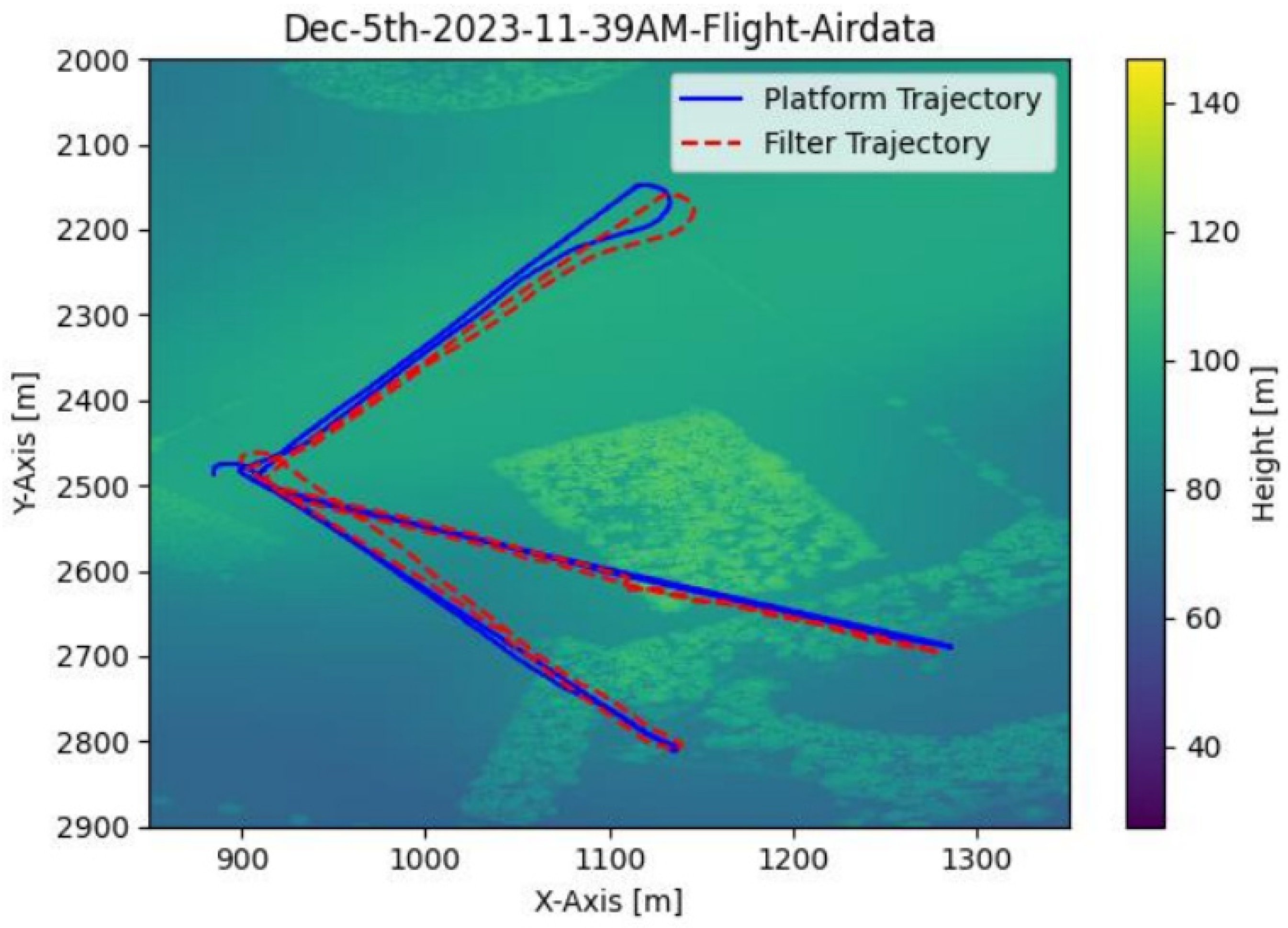
An example result comparing the true and TRN-aided trajectory estimates is shown in
Figure 5. In this scenario, the drone took off and landed at the same point—at approximately x = 900 m and y = 2480 m. It flew three separate return trajectories on different headings.
Figure 6 then shows the error of the TRN-aided positional estimate as a function of time. For reference, the positional error growth based purely on dead reckoning by integrating the drone’s airspeed data from the known start position is provided. In this example, the radar mm-wave TRN constrains error growth to less than 20 m over the entire trajectory—whereas integration of airspeed data leads to error growth in excess of 100 m (note that errors greater than 100 m not shown in the figure to retain a sensible scale on the radar TRN error). A key source of error when estimating position through dead reckoning via integration of airspeed data is wind (approximately 5 m/s during the course of the experiments). No attempt was made to estimate or compensate for the wind velocity vector to derive a more accurate estimate of ground speed. In lighter wind conditions, the error growth in the dead reckoning position estimate is expected to grow more slowly than observed. However, as errors compound during dead reckoning, the dead reckoning positional error will continue to grow unbounded over time.
6. Conclusions
This paper presents results from an experimental mm-wave radar TRN system suitable for small drones. The TRN system is composed of a mm-wave radar, a particle filter, and a digital elevation map of the local environment. The TRN system combines altimetry data from the radar with barometer-derived altitude measurements to estimate the elevation of the ground below the drone. The particle filter is then used to fuse airspeed data from the drone with the measured ground elevation and the digital elevation map to provide a position estimate independent of GNSS.
The results show that such a system can measure the ground’s elevation profile to enable a drone to navigate accurately in the absence of GNSS. The performance of such a system will, however, be limited by the fidelity and accuracy of the elevation map, the accuracy of the radar-derived ground elevation, and the feature density of the ground elevation profile. In addition, inclement weather and seasonal variation in the ground (e.g., foliage, river levels) are likely to affect performance.
Author Contributions
Conceptualization, A.C.; methodology, J.M.; software, J.M.; validation, J.M.; formal analysis, J.M.; investigation, J.M.; resources, A.C.; data curation, J.M.; writing—original draft preparation, A.C. and J.M.; writing—review and editing, J.M.; visualization, J.M.; supervision, A.C.; project administration, J.M.; funding acquisition, A.C. All authors have read and agreed to the published version of the manuscript.
Funding
This research was funded by the Defense and Security Accelerator, grant number ACC6046723.
Institutional Review Board Statement
Not applicable.
Informed Consent Statement
Not applicable.
Data Availability Statement
Data can be shared with research institutions for academic research. Please email the authors for further details.
Conflicts of Interest
The authors declare no conflicts of interest.
References
- Hsu, J. Unprecedented GPS Jamming Attack Affects 1600 Aircraft over Europe. Available online: https://www.newscientist.com/article/2424678-unprecedented-gps-jamming-attack-affects-1600-aircraft-over-europe/ (accessed on 30 April 2024).
- Gyagenda, A.; Hatilima, J.V.; Roth, H.; Zhmud, V. A review of GNSS-independent UAV navigation techniques. Robot. Auton. Syst. 2022, 152, 104069. [Google Scholar] [CrossRef]
- AL-Kaff, A.; Martin, D.; Garcia, F.; Escalera, A.; Armingol, J. Survey of computer vision algorithms and applications for unmanned aerial vehicles. Expert Syst. Appl. 2018, 92, 447–463. [Google Scholar] [CrossRef]
- Cowie, I.; Wilkinson, N. The TERPROM® Digital Terrain System (DTS). J. Aerosp. Sci. Technol. 2009, 61, 259–270. [Google Scholar] [CrossRef]
- Cowie, I.; Wilkinson, N.; Powlesland, R. Latest development of the TERPROM® Digital Terrain System (DTS). In Proceedings of the 2008 IEEE/ION Position, Location and Navigation Symposium, Monterey, CA, USA, 5–8 May 2008. [Google Scholar]
- Coleman, G.; Seelos, M.; McAllum, S. Developmental flight testing of a digital terrain system for the USAF F-16. In Proceedings of the IEEE Aerospace Conference, Snowmass, CO, USA, 7 March 1999. [Google Scholar]
- Tsai, S.-X. Introduction to the Scene Matching Missile Guidance Technologies; Report number NAIC-ID(RS)T-0379-96; National Air Intelligence Centre: Wright Patterson Air Force Base, OH, USA, 1996. [Google Scholar]
- IWR6443 Single-Chip 60- to 64-GHz mmWave Sensor. Available online: https://www.ti.com/lit/ds/symlink/iwr6843.pdf?ts=1714733909651 (accessed on 3 May 2024).
- PLX-T60 Configurable mm-Wave Radar Module. Available online: https://www.plextek.com/wp-content/uploads/2024/06/PLX-T60-Configurable-mm-wave-radar-module.pdf (accessed on 3 May 2024).
- Defra Survey Data Download. Available online: https://environment.data.gov.uk/survey (accessed on 3 May 2024).
- Sanjeev, M.; Maskell, S.; Gordon, N.; Clapp, T. A Tutorial on Particle Filters for Online Nonlinear/Non-Gaussian Bayesian Tracking. IEEE Trans. Signal Process. 2002, 50, 174–188. [Google Scholar]
| Disclaimer/Publisher’s Note: The statements, opinions and data contained in all publications are solely those of the individual author(s) and contributor(s) and not of MDPI and/or the editor(s). MDPI and/or the editor(s) disclaim responsibility for any injury to people or property resulting from any ideas, methods, instructions or products referred to in the content. |
© 2025 by the authors. Licensee MDPI, Basel, Switzerland. This article is an open access article distributed under the terms and conditions of the Creative Commons Attribution (CC BY) license (https://creativecommons.org/licenses/by/4.0/).

