Abstract
The design and optimization of supersonic nozzles are of great interest in aerospace and propulsion system applications. Designing and maintaining a mechanically simple nozzle would be beneficial over the complex nozzles that are currently in use. A detailed simulation-based study was conducted to design a virtual nozzle that produces the same effect as a traditional nozzle while using simpler geometries and secondary air injection. Secondary air injection is widely used for fluidic thrust vectoring. Because such a nozzle is operated by varying the thickness of the boundary layer, it is possible to control the effective throat area, and hence, achieve a variety of exit pressures and Mach numbers by just varying the input momentum ratios (or pressure ratios). A similar concept was kept in mind, and various geometries, such as flat-plate geometry, divergent geometry and convergent–divergent geometry, were tested for different jet pressure ratios, numbers of jets, locations of the jets and geometric parameters of the virtual nozzle. The main objective of the work was to achieve an exit Mach number of 2 from a subsonic flow. The lengths of various geometries and the input pressure ratios were altered iteratively based on the findings obtained in each test case. All of the results attempted to acquire the required exit Mach number while accounting for numerous complexities in fluid flows, such as shock waves, vorticities, etc. Although the desired Mach number is not achieved, this study establishes a strong foundation and an idea that has the potential to revolutionize propulsion systems and create nozzles that are mechanically simple, weigh less and do not require any actuating mechanisms to operate.
1. Introduction
Supersonic nozzles are used to expand the free stream flow to desired supersonic conditions. The secondary fluidic injection is also of practical interest. The thrust vectoring of rockets for better maneuverability at low pressures and low Mach numbers, as well as the mixing of air and fuel in supersonic combustors, are examples of this phenomenon. Fluidic thrust vectoring is the process of controlling a rocket engine’s exhaust flow through the use of a secondary air source, typically the bleed air coming from the engine compressor or fan. In the current work, detailed simulation-based research is conducted to study the injection of secondary fluid to control the flow separation and throat area of a primary air jet in order to design a virtual two-dimensional nozzle that is much simpler than mechanical nozzles. The injection takes place through two or three cylindrical orifices of a certain thickness each. The goal is to achieve an exit supersonic flow with a Mach number of 2 from an inlet subsonic flow with a Mach number of 0.3. This is accomplished by altering the effective throat area between the two flat plates by varying the thickness of the boundary layer by either injecting it on one or both sides. Because the pressure at which the secondary air is injected determines the thickness of the boundary layer, the diameters of the cylindrical orifices are chosen accordingly. Therefore, to ensure precision in determining the penetration depth, the thickness of the boundary layer and the effective throat area, a thorough attempt was made to consider different pressure ratios and orifice diameters. It is possible to design an effective supersonic nozzle by carefully selecting the momentum ratios (pressure ratios) and the physical dimensions of the structures involved. This work explores the effect of transverse air injection into the primary flow stream using commercial CFD software, ANSYS FLUENT 2022 R2 (student version). Therefore, a progressive attempt was made to design a virtual two-dimensional nozzle with a secondary injection to eliminate the complexities involved in mechanical nozzles and achieve supersonic flow over a shorter distance with better mixing. The scope of this work is further expanded by analyzing the divergent and convergent–divergent geometries along with the flat-plate geometry. Injections on one and both sides are also investigated. Karen A Deere et al. [1] performed extensive research on dual-throat thrust vectoring nozzles. Such nozzles give larger thrust vectoring efficiencies than the throat shifting method and the shock vector control method, without compromising the thrust ratio, by continuously checking the separation and increasing the pressure gradient across the recessed cavity. One of the prominent results was that, for NPR = 4, the efficiency of thrust vectoring obtained experimentally was 6.1 degrees per percent injection with around 1 percent injection, and the thrust ratio was found to be 0.968, which was a 0.5 percent loss as compared to the non-vectoring case. In the study performed by Vivek Kishanlal Bhati et al. [2], the results showed that the surface pressures that were computed were in good consideration with the experimental results for momentum ratios of 1.16, 2.75, 4 and 5.30. It was inferred that the penetration depth and spreading of the injected fluid showed a linear dependence on the momentum ratios. Research carried out by Ben-Yakar et al. [3] shows that various flow parameters, such as the operating altitude, Mach number, pressure ratios of the jet and the free stream, and diameter and shape of the injecting jet nozzle, have a significant effect on the penetration of the jet stream into the supersonic free stream. The predictive capabilities of the SST—kω turbulence model and the kε—realizable turbulence model were compared. In the computational study performed by Emanuele Resta et al. [4], the Mach numbers and density contours for distinct normal pressure ratios and Mach numbers of 0.6, 0.9 and 1.2 were studied. They also suggested that the mass flow rate of the secondary jet and the area of opening can influence the effect of injection on the main primary flow. Vatsalya Sharma et al. [5] calculated the reattachment length upstream of the injection position. A small difference in normalized pressure distribution was observed between the simulation results and the experiments. In the work by G. Aswin et al. [6], it is evident from the results that, with the increase in the pressure ratio, the size of the barrel shock also increases. Ali Abdul Almuhsen Al-Asady et al. [7] researched the co-flow method and observed that beyond the dead zone, the thrust vectoring angle increases as the mass flow increases. In the experimental and simulation-based studies conducted by S. Aso et al. [8], a robust analysis of the effect of injection angle for supersonic mixing using a circular nozzle has been done. Raman G et al. [9] proved that fluidic actuators that can produce distributed addition of mass can be used for vectoring the flow. Karen A Deere et al. [10] found out that a large deflection in fluid flow was observed by the shock vector control method and the angle of injection is a crucial parameter for achieving this. Research carried out by Ibrahim Mnafeg et al. [11] and Vladeta Zmijanovic [12] displayed that the angle of deviation depends on the geometric parameters of the injector, the location of the injector, and the pressure ratio at which the secondary fluid is injected. Michele Trancossi [13] explored the use of Coanda nozzles for deflecting the primary fluid flow. Shigeru Aso et al. [14] showed that, for slotted injection, the effect of aerodynamic fences has to be considered. Neilson et al. [15] studied the effect of fluidic injection in rocket nozzles and Louis A. Cassel [16] studied the response of aircraft under an ambient atmospheric environment. Bernhard Stahl and Helmut Esch [17] experimentally measured the wall pressures for distinct flow injection setups. Chamberlain [18] employed Roe’s scheme to study the three-dimensional jet interaction case. Spalart [19] used a local model that gives accurate results in the wake region and can be employed for complex fluid flows. Champigny [20] showed that at low pressure, side jet control is better than aerodynamic control. After learning about the history of work in this domain, it is clear that, while much work has been done on analyzing the application of secondary injection in thrust vectoring for various geometries, an extensive assessment of the simplest of the geometries, the flat plate, has not been carried out. Injection through both sides of the geometry for various input parameters has also received little interest. In the present work, efforts are made to address these aspects and detail the results.
2. Methodology
In order to achieve supersonic flow at the exit, various geometries of flat plate and converging–diverging sections are tested with different boundary conditions. A two-dimensional design is developed for simplicity and to reduce the computational power required. All the mesh elements are quadrilateral-shaped. The main advantage of using a structured mesh is that it is simple and efficient computationally. Structured mesh uses less memory as compared to unstructured mesh for the same number of elements, and the compilers have reduced execution times in the context of structured meshing because they efficiently compute different parameters using the finite volume method by simply incrementing or decrementing array indices to access specified elements. This methodology is particularly advantageous when dealing with simple geometric setups, such as in this work, The mesh metrics show that the average orthogonal quality is close to 1 and the skewness is of very low order, indicating that a high-quality mesh was produced.
2.1. Design and Meshing
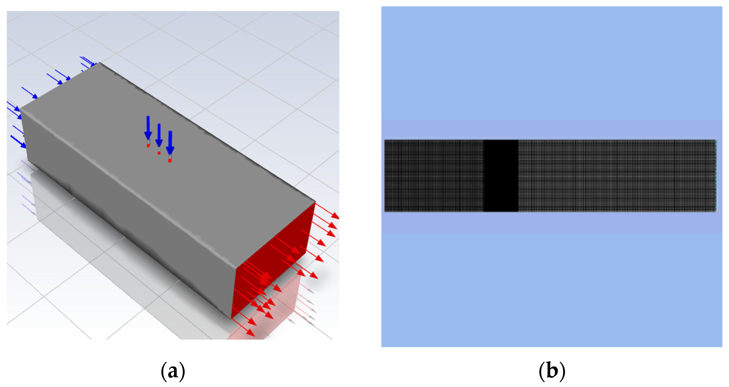
Firstly, single-side injection through a two-dimensional flat plate was investigated. Flat plates with lengths of 200 mm each and a 50 mm distance between them were chosen, with three injectors with diameters of 2 mm, 1.5 mm and 2 mm and a pitch of 10 mm between them. The injection takes place at the center of the flat plates. This is illustrated in Figure 1a. To achieve supersonic flow at the exit, several boundary conditions were tested. A finer mesh was used around the region where the jet injectors lie, and a coarser mesh was used everywhere else. The meshing for one of the cases with flat-plate geometry is shown in Figure 1b. All of the other cases used a similar type of mesh. Following this, simulations were run for a variety of flat-plate lengths, the distances between them, injector positioning, orifice diameters and two-side injection as shown in Table 1.

Figure 1.
Computational domain: (a) design of flat-plate geometry with inlet and outlet flows represented by blue and red colors respectively; (b) structured meshing.

Table 1.
Test cases for the flat-plate geometry.
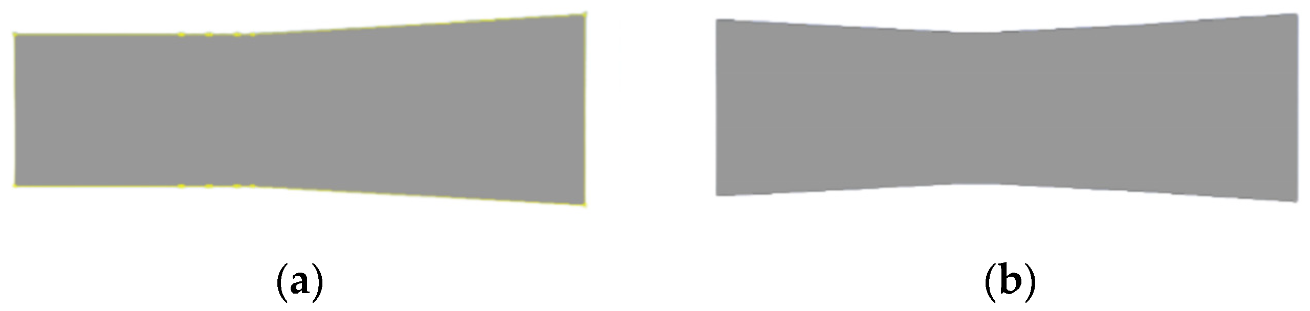
Next, a divergent section downstream of the rightmost orifice was introduced to reduce the thickness of the wake region by allowing the flow to expand freely and expanding the shock waves beyond the virtual nozzle, as shown in Figure 2a. The angle of divergence was 3 degrees, and different lengths of the slanted edge were tested out as represented in Table 2. Following this, a convergent–divergent configuration with a 3-degree angle of convergence and divergence was designed and simulated. Finally, another divergent section was added downstream of the first divergent section to further expand the flow, as shown in Figure 2b. The angle of divergence of this was increased by 3 more degrees. Various parameters used for this case is shown in Table 3.
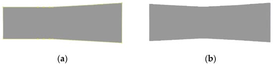
Figure 2.
Nozzle designs. (a) Divergent geometry downstream. (b) Convergent–divergent geometry.
Table 2.
Test cases for divergent geometry.
Table 3.
Test cases for convergent–divergent and double-divergent geometry.
2.2. Setup and Boundary Conditions
Since supersonic flow takes place, there will be variations in the density of the fluid, and hence, the compressibility effects cannot be ignored. To accommodate this, a density-based solver was used. Furthermore, absolute velocity formation was preferred as relativity is used when the fluid domain is divided into multiple subdomains. The density of air was set as the ideal gas as the fluid flow is compressible. The realizable k—ε turbulence model was used as a laminar model (no turbulence) for a fluid flow over an object that is turbulent in reality, or destructively negates the effect of the driven forces, eddies, vorticities, etc. The inlet subsonic Mach number and an exit Mach number of 2 were used to develop the inlet pressure, outlet pressure and velocity boundary conditions. The isentropic flow equation shown below is used to calculate the pressure necessary to achieve a supersonic flow with a Mach number of 2.
The fundamental equation shown below is used to calculate the inlet velocity. The first test case in the Results and Discussion section, for example, considers an inlet velocity of 104.15 m/s. This is obtained by merely setting the inlet Mach number to 0.3 (subsonic, as discussed) and the temperature to 300 K.
3. Results and Discussion
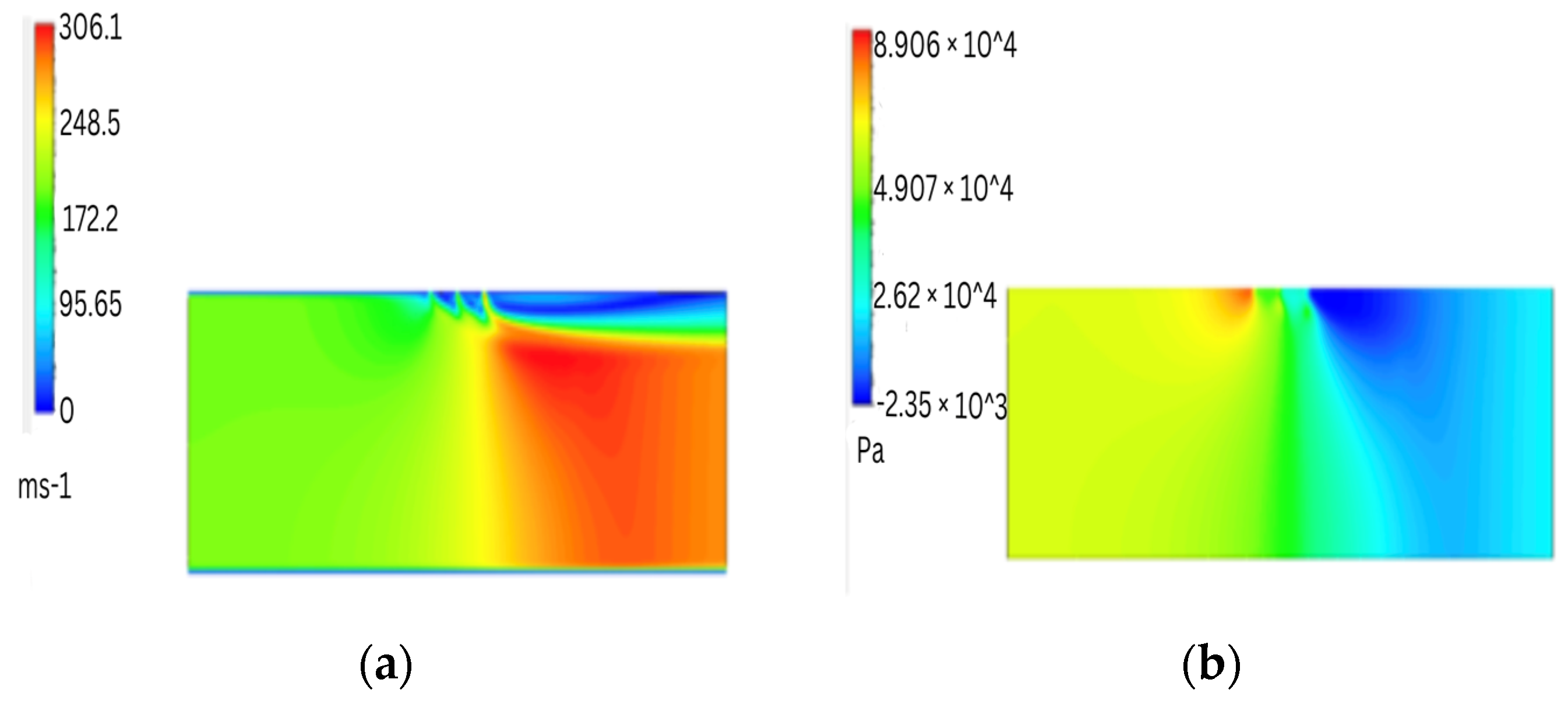
Flat plates of 200 mm in length and with 50 mm spacing were chosen, with three injectors with 2 mm, 1.5 mm and 2 mm diameters and a pitch of 10 mm between them. The injection took place at the center of the flat plates. Several boundary conditions were tested in order to achieve supersonic flow at the exit. The inlet velocity was taken as 104.15 m/s (corresponding to Mach number = 0.3). Following this, the outlet pressure was set to 0.127 bar (corresponding to Mach number = 2). For a given inlet pressure of 1 bar, pressure ratios of 1.1, 1.2, and 1.3 were tested. Since supersonic flow is not observed, the distance between the plates was increased from 50 mm to 70 mm to allow for a sufficient gap for the flow to get accelerated. The results for a pressure ratio of 1.1 are shown in Figure 3.
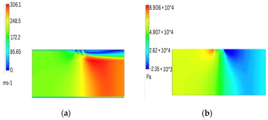
Figure 3.
Results for PR = 1.1. (a) Velocity contour; (b) pressure contour.
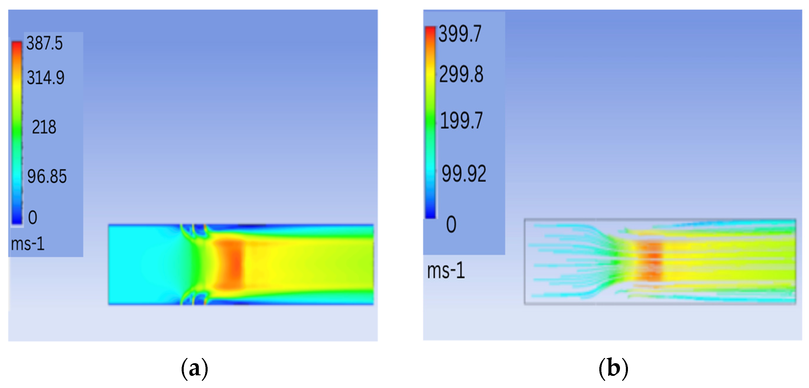
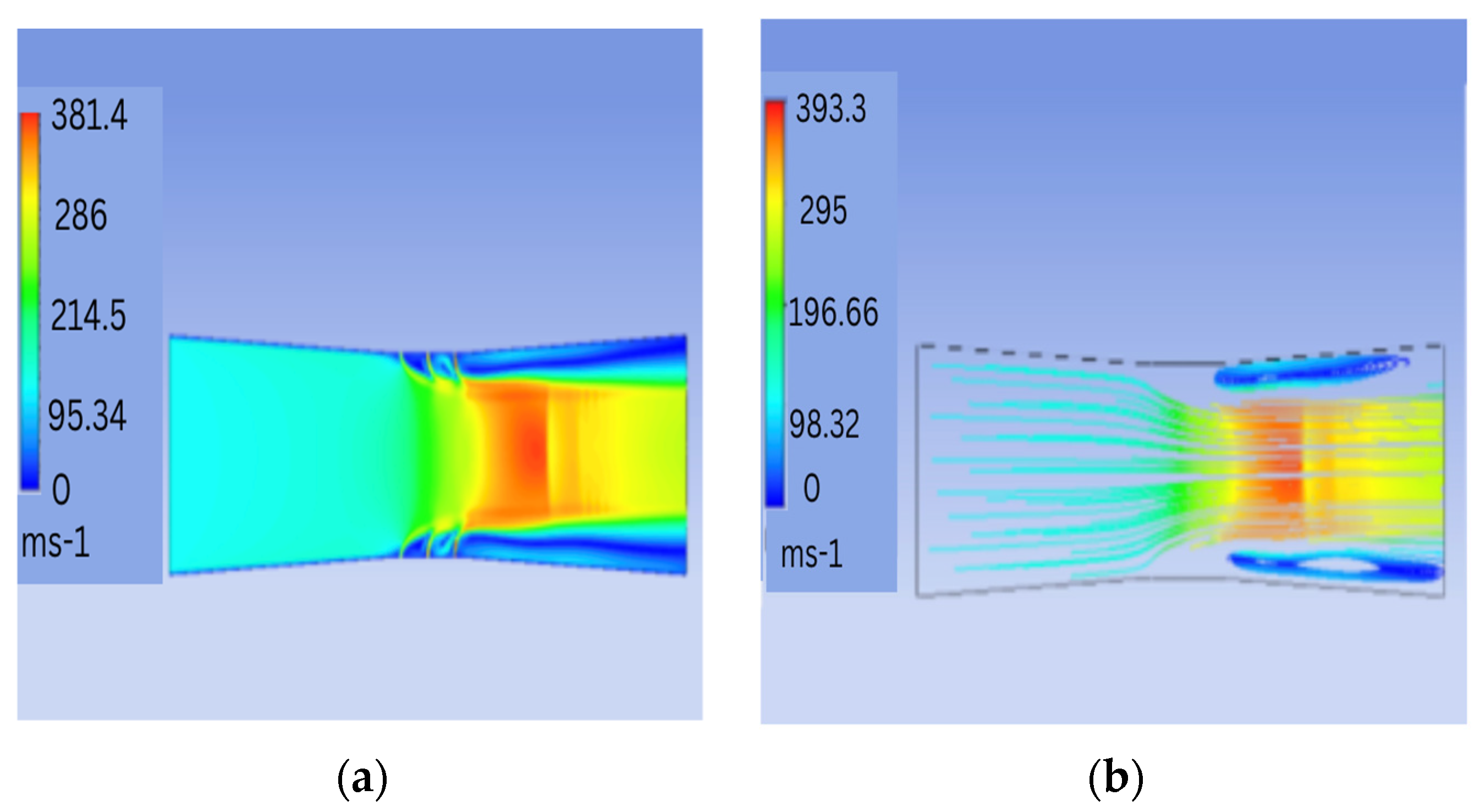
In any of the preceding cases, the expected supersonic flow with a Mach number of 2 is not observed. This is because the injected secondary fluid does not sufficiently compress the incoming flow to supersonic speeds. To achieve supersonic speeds, the secondary fluid was injected symmetrically from both sides and the injectors were located at the center of the flat plate. The length of the flat plates and the distance between them were maintained at 200 mm and 50 mm, respectively. A thorough computational analysis was performed for pressure ratios of 1.2, 2, 3 and 3.5. All other parameters and boundary conditions remained unchanged from the previous cases. The velocity contours and the velocity streamlines for a pressure ratio of 1.2 are shown in Figure 4.
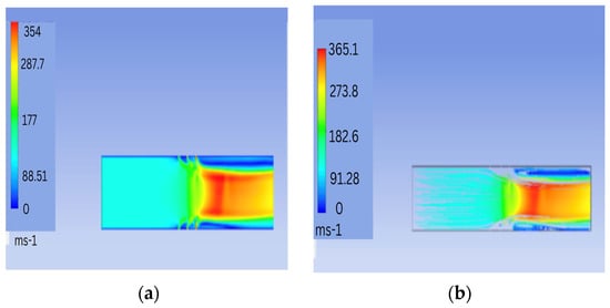
Figure 4.
Results for PR = 1.2. (a) Velocity contour; (b) velocity streamlines.
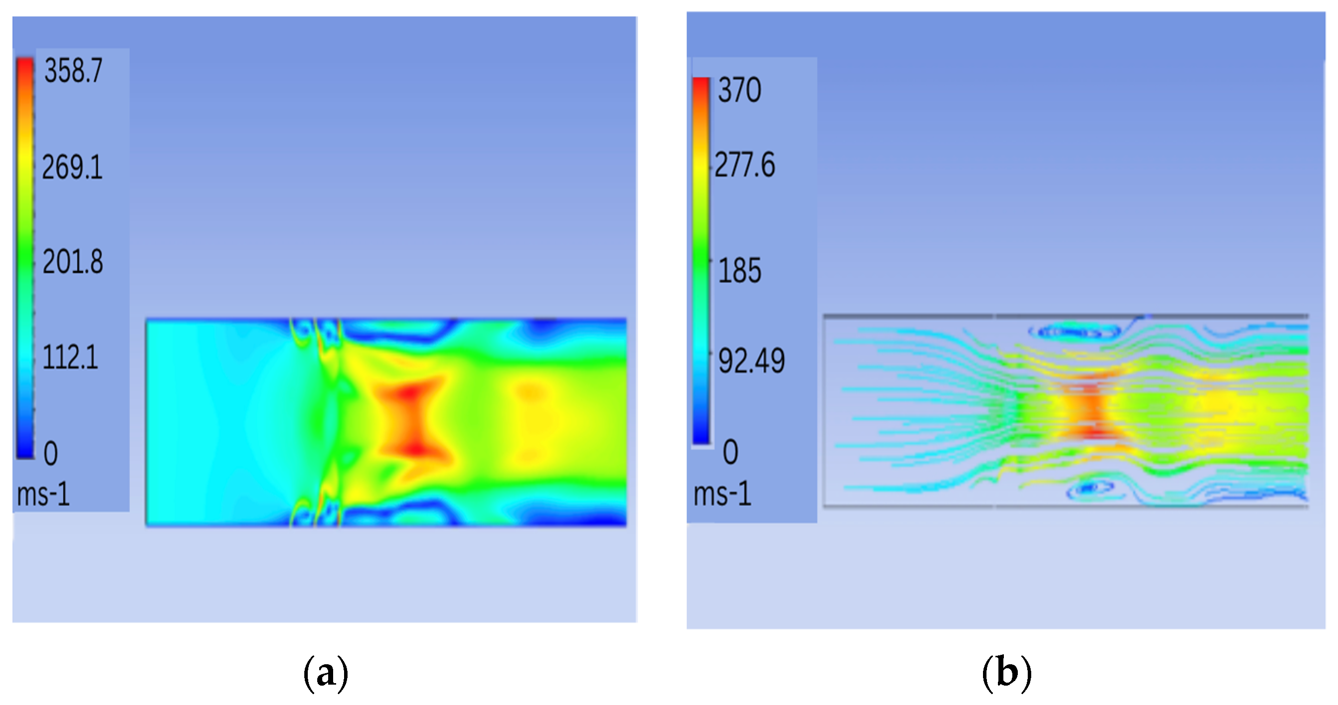
Diamond-shaped shock waves are observed for pressure ratios of 2 and above, which are not of practical significance in the current work. The injectors were then moved 30 mm upstream, and the flat plates downstream were lengthened by 20 mm. This was carried out to give the secondary jet sufficient room to compress the primary air flow and achieve effective supersonic flow at the exit by pushing the shock waves out of the domain. As a result, the flat plates were 220 mm long with a 50 mm gap between them. Pressure ratios of 1.2, 1.35, 1.5, 2, 3, and 3.5 are observed in detail and one such result is shown in Figure 5.

Figure 5.
Results for PR = 1.35. (a) Velocity contour; (b) velocity streamlines.
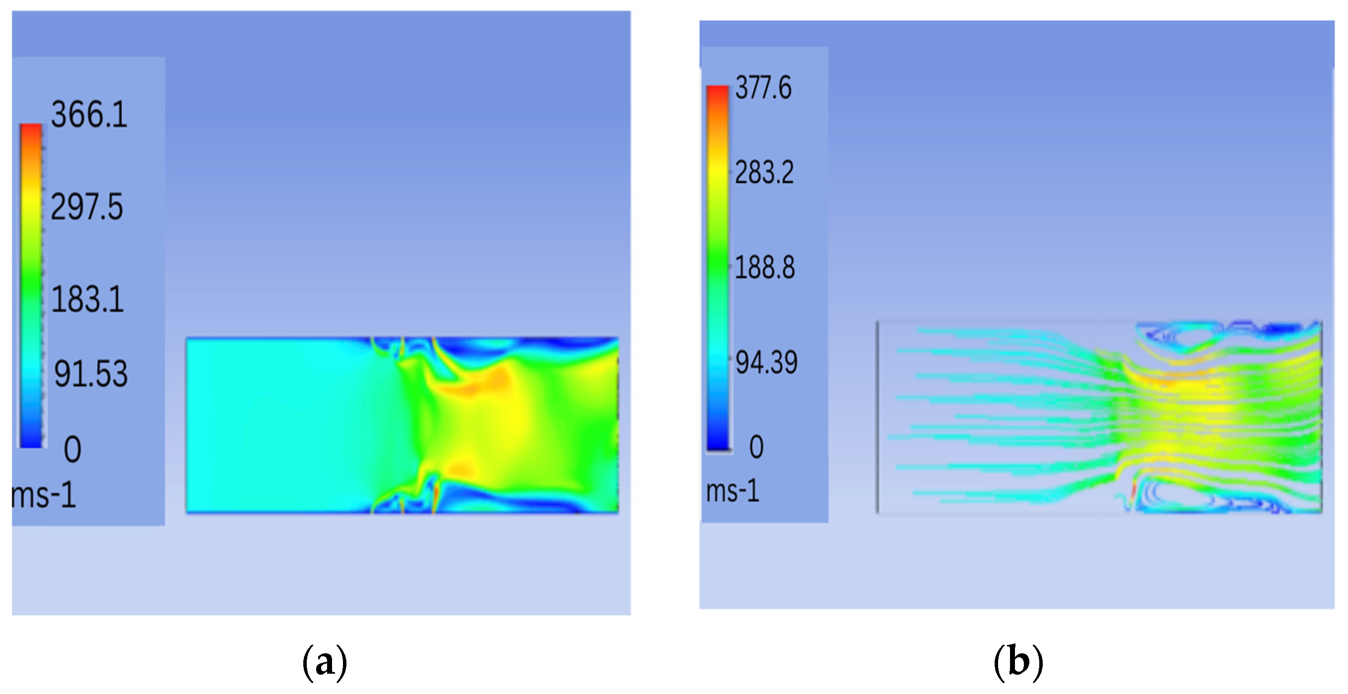
Shock waves are observed to form at pressure ratios greater than 1.35. As a result, with these dimensions and boundary conditions in consideration, a pressure ratio of 1.35 was chosen for the subsequent analysis. Following this, an attempt was made to achieve a divergent-like effect by using orifices with varying diameters in order to allow space for the vorticities to expand and sufficient space for the flow to accelerate. For the same mass flow rate, the velocity of the impinging secondary jet stream decreases as the orifice diameter increases. As a result, a divergent-like effect was predicted for orifices with diameters of 0.8 mm, 1 mm and 1.2 mm, respectively. The boundary conditions for this case are the same as in the previous cases, and the pressure ratio is considered to be 1.35. For such a case, the velocity contour and velocity streamline are shown in Figure 6.
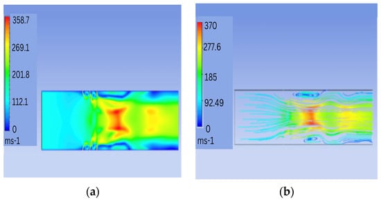
Figure 6.
Varying orifice diameters with PR = 1.35. (a) Velocity contour; (b) velocity streamlines.
We can observe strong vortices soon after the injection zone. To reduce the strength of these circulations, the diameter of the orifices was increased. Orifices with diameters of 1 mm, 1.2 mm and 1.4 mm were simulated. The vortices’ strength was decreased, but a supersonic flow with a Mach number of 2 was still not achieved at the exit. The injection location was shifted back to the center of the flat plates in order to shift the throat of the virtual nozzle downstream to achieve choked flow near the exit. The velocity contour and streamlines shown in Figure 7 are obtained for orifices with diameters of 0.8 mm, 1 mm and 1.2 mm, with injection taking place in the center and all other parameters staying the same. Next, a divergent section (length of the slanted edge = 100 mm and angle of divergence = 3 degrees) 5 mm downstream of the rightmost orifice with a diameter of 1.2 mm was introduced to reduce the thickness of the wake region by allowing the flow to expand freely and expanding the shock waves beyond the virtual nozzle. All the other boundary conditions and parameters were kept the same. Several other test cases were simulated. The first is one with the length of the divergent section set to 150 mm. The second is one with an inlet pressure of 2 bar and an inlet velocity of 104.15 m/s (corresponding to Mach number = 0.3), an outlet pressure of 0.254 bar (corresponding to Mach number = 2) and a jet pressure of 2.7 bar. The third is one with two orifices with diameters of 0.8 mm and 1 mm. However, none of the preceding cases delivered the intended result because it is difficult to obtain a supersonic flow due to short mixing distances. Following this, a convergent–divergent configuration with a 3-degree angle of convergence and divergence was simulated. For a 1 bar inlet pressure, orifices with diameters of 1 mm each, a jet pressure of 1.35 bar and a converging/diverging length of 80 mm, the results are as shown in Figure 8.
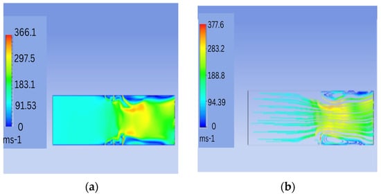
Figure 7.
Varying orifice diameters (0.8 mm, 1 mm, 1.2 mm). (a) Velocity contour; (b) velocity streamlines.
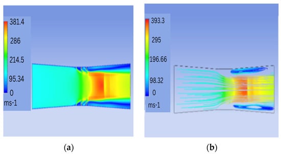
Figure 8.
Convergent–divergent geometry. (a) Velocity contour; (b) velocity streamlines.
In the above case, even though a flow with a Mach number of 2 is not achieved, we observe a continuous supersonic flow. Finally, by adding another diverging section downstream of the first, the angle of divergence is increased by 3 more degrees. The slant height of both diverging sections was kept constant at 50 mm. The objective of introducing a diverging section at the exit was to allow the flow to freely expand and push the shock waves beyond the exit. All the other boundary conditions and flow parameters remained constant. As a result, for a 3-degree angle of convergence and two divergent sections, with a 3-degree angle of divergence for the first and a 6-degree angle of divergence for the second, the results are observed closely.
4. Conclusions
This project’s primary task is to predict the upstream and downstream lengths, as well as the orifice diameters, that will affect jet pressure ratios. Various geometries are designed and simulated to achieve supersonic flow with a Mach number of 2. For the flat-plate geometry, the effects of single-sided and double-sided injection for various injector positions and jet pressure ratios are explored. A divergent section downstream of the injection is then designed to reduce the strength and thickness of the wake region, resulting in supersonic flow at the output. Finally, a convergent section is designed upstream of the injection location and a divergent section is designed downstream of the injection location. Several jet pressure ratios are tested in order to achieve supersonic flow at the exit with a Mach number of 2. Even though a Mach number of 2 was not achieved in this work, it does lay a good and solid foundation for future research in this domain. The Results section provides an excellent comparison of various cases. It is possible to design a virtual nozzle that can replace traditional mechanical nozzles in many applications by accurately selecting the geometric parameters along with boundary conditions. The thorough testing of various input parameters, such as geometry dimensions, injector locations and injector diameter, using advanced CFD simulations to achieve choked flow is one promising avenue of research. Furthermore, conducting experimental studies to validate the simulation-based results would benefit the proposed model’s credibility and real-world applicability.
Author Contributions
Conceptualization, G.V.; methodology, P.S. and G.V.; software, P.S. and G.N.K.; validation, P.S. and G.V.; formal analysis, P.S., G.V., M.V.R. and P.K.U.; investigation, P.S. and G.V.; resources, G.V. and G.N.K.; writing—original draft preparation, P.S.; writing—review and editing, P.S. and G.V.; visualization, P.S., G.V. and G.N.K.; supervision, G.N.K., M.V.R. and P.K.U.; project administration, M.V.R., P.K.U. and G.N.K. All authors have read and agreed to the published version of the manuscript.
Funding
This research received no external funding.
Institutional Review Board Statement
Not applicable.
Informed Consent Statement
Not applicable.
Data Availability Statement
Data are unavailable.
Acknowledgments
We thank the Director of NITK and the Director of CSIR NAL.
Conflicts of Interest
The authors declare no conflicts of interest.
References
- Deere, K.A.; Berrier, B.L.; Flamm, J.D.; Johnson, S.K. A Computational Study of a New Dual Throat Fluidic Thrust Vectoring Nozzle Concept. In Proceedings of the 41st AIAA/ASME/SAE/ASEE Joint Propulsion Conference & Exhibit, Tucson, Arizona, 10–13 July 2005. AIAA Paper 2005-3502. [Google Scholar]
- Bhati, V.K.; Chakraborty, D. Numerical Exploration of Transverse Sonic Jet In Hypersonic Cross-flow. J. Aerosp. Sci. Technol. 2022, 74, 143–150. [Google Scholar] [CrossRef]
- Ben-Yakar, A.; Mungal, M.G.; Hanson, R.K. Time evolution and mixing characteristics of hydrogen and ethylene transverse jets in supersonic crossflows. Phys. Fluids 2006, 18, 026101. [Google Scholar] [CrossRef]
- Resta, E.; Marsilio, R.; Ferlauto, M. Thrust Vectoring of a Fixed Axisymmetric Supersonic Nozzle Using the Shock-Vector Control Method. Fluids 2021, 6, 441. [Google Scholar] [CrossRef]
- Sharma, V.; Chakraborty, D.; Eswaran, V. Computational Study of Sonic Injection in Supersonic Crossflow. In Proceedings of the 7th International and 45th National Conference on Fluid Mechanics and Fluid Power (FMFP), IIT Bombay, Mumbai, India, 10–12 December 2018. [Google Scholar]
- Aswin, G.; Chakraborty, D. Numerical simulation of transverse side jet interaction with supersonic free stream. Aerosp. Sci. Technol. 2010, 14, 295–301. [Google Scholar] [CrossRef]
- Al-Asady, A.A.A.; Abdullah, A.M. Fluidics Thrust Vectoring Using Co-Flow Method. Al-Nahrain J. Eng. Sci. (NJES) 2017, 20, 5–18. [Google Scholar]
- Aso, S.; Inoue, K.; Yamaguchi, K.; Tani, Y. A study on supersonic mixing by circular nozzle with various injection angles for air breathing engine. Acta Astronaut. 2009, 65, 687–695. [Google Scholar] [CrossRef]
- Raman, G.; Packiarajan, S.; Papadopoulos, G.; Weissma, C.; Raghu, S. Jet Thrust Vectoring using a Miniature Fluidic Oscillator. In Proceedings of the ASME 2001 Fluids Engineering Division Summer Meeting Conference, New Orleans, LA, USA, 10–12 August 2021. [Google Scholar]
- Deere, K.A. Summary of fluidic thrust vectoring research conducted at NASA LANGLEY research center. In Proceedings of the 21st Applied Aerodynamics Conference, Orlando, FL, USA, 23–26 June 2003. AIAA 2003-3800. [Google Scholar]
- Mnafeg, I.; Abichou, A.; Beji, L. Thrust Vectoring Control of Supersonic Flow Through an Orifice Injector. Eng. Technol. Int. J. Aerosp. Mech. Eng. 2015, 9, 1352–1358. [Google Scholar]
- Zmijanovic, V.; Lago, V.; Sellam, M.; Chpoun, A. Thrust shock vector control of an axisymmetric conical supersonic nozzle via secondary transverse gas injection. Shock. Waves 2013, 24, 97–111. [Google Scholar] [CrossRef]
- Trancossi, M. An Overview of Scientific and Technical Literature on Coanda Effect Applied to Nozzles; SAE Technical Paper; SAE: Warrendale, PA, USA, 2011; No. 2011-01-2591. [Google Scholar]
- Aso, S.; Okuyama, S.; Ando, Y.; Fujimori, T. Two-dimensional and three-dimensional mixing flow fields in supersonic flow induced by injected secondary flows through traverse slot and circular nozzle. In Proceedings of the 31st Aerospace Sciences Meeting, Reno, NV, USA, 11–14 January 1993; p. 489. [Google Scholar]
- Neilson, J.H.; Gilchrist, A.; Lee, C.K. Side Thrust Control by Secondary Gas Injection into Rocket Nozzles. J. Mech. Eng. Sci. 1968, 10, 239–251. [Google Scholar] [CrossRef]
- Cassel, L.A. Applying jet interaction technology. J. Spacecr. Rocket. 2003, 40, 523–537. [Google Scholar] [CrossRef]
- Stahl, B.; Esch, H.; Gulhan, A. Experimental investigation of side jet interaction with a supersonic cross flow. Aerosp. Sci. Technol. 2008, 12, 269–275. [Google Scholar] [CrossRef]
- Chamberlain, R. Calculation of three-dimensional jet interaction flow field. In Proceedings of the 26th Joint Propulsion Conference, Orlando, FL, USA, 16–18 July 1990. AIAA paper no. 90-2099. [Google Scholar]
- Spalart, P.R.; Allmaras, S.R. A one-equation turbulence model for aerodynamic flows. In Proceedings of the 30th Aerospace Sciences Meeting and Exhibit, Reno, NV, USA, 6–9 January 1992. [Google Scholar]
- Champigny, P.; Lacau, R.G. Lateral jet control for tactical missiles. AGARD Rep. 1994, 4, 301–3057. [Google Scholar]

Disclaimer/Publisher’s Note: The statements, opinions and data contained in all publications are solely those of the individual author(s) and contributor(s) and not of MDPI and/or the editor(s). MDPI and/or the editor(s) disclaim responsibility for any injury to people or property resulting from any ideas, methods, instructions or products referred to in the content. |
© 2024 by the authors. Licensee MDPI, Basel, Switzerland. This article is an open access article distributed under the terms and conditions of the Creative Commons Attribution (CC BY) license (https://creativecommons.org/licenses/by/4.0/).