Abstract
The subject of this study is the dynamic analysis of the energy flow in the transient mode of the movement of the vehicle with a kinetic accumulator, implemented with a purely mechanical transmission. The elements of which include—a flywheel, planetary gears with two degrees of freedom, some ordinary gears, a friction mechanism with a variable transmission ratio (CVT), and a certain number of brake clutches, etc. A control algorithm is proposed; the differential equations of motion are derived and solved. The effectiveness and applicability of such a purely mechanical transmission for accumulating and realizing energy during braking and accelerating of the electro-mobile are proven, in which it is possible to extend the range by up to 12–14%.
1. Introduction
In the 1950s, Oerlicon (Switzerland) produced an experimental trolleybus with a propulsion system containing a kinetic energy storage system–flywheel. It was a reversible electric machine and a motor/generator was built into its core. The flywheel was monolithic, with mass of 3 × 10³ [kg], a diameter of about 1.5 [m], and a maximum permissible rotation speed of 300 [s−1] [1]. This trolleybus, later called the Gyrobus, could in a charged state travel a distance of about 2 [km] until the next charging with energy.
In essence, from that moment on a very active scientific research activity began all over the world in the field of kinetic technologies in various areas of the industry.
Prof. D. W. Rabenhorst from John Hopkins University—USA, can be noted as one of the pioneers in this direction [1].
At beginning of the century, stationary kinetic storage systems with a maximum power in the range of 10 to 500 [kw] were put in regular production and offered on the market [2]:
- As a variety of substations along the largest railway high-lines in the USA and EU, with a power of up to 500 [kw] [3];
- As Uninterruptible Power Systems (UPSs) [4];
- As lifting facilities (hydraulic elevators, container handling equipment at large ports) [5];
- Stationary storage devices with general purpose [6];
- As well as in transport equipment with the ability to recover energy during vehicle braking and other scenarios.
Kinetic energy systems are used in wind farms and recently they have replaced high-power, pumped-energy accumulating plants in the USA and China [7,8]. It is quite possible that these technologies will find their place in military affairs and in space under the natural conditions of vacuum and weightlessness.
A kinetic storage system is added in the propulsion systems of Formula One cars [9,10,11] to the main source of energy in an internal combustion engine (ICE),—a super flywheel and a continuous variable transmission (CVT). When cornering on a track, when the speed is sharply reduced the braking energy is stored in the super flywheel, which is subsequently released when the car accelerates.
There are studies in the scientific literature on similar propulsive systems consisting of a main and additional source of energy [12], with the ability to recuperate energy during braking of the vehicle [13], and with a different topological structure [14]—parallel, in series, and some combinations.
A computer simulation in [15] proves that an electric vehicle with a kinetic storage system has about 11–14% increased mileage on one charge of its electric battery, with the research demonstrating it for five of the most common transport cycles in a large city.
The purpose of this study is to analyze the proposed structural scheme for driving a hybrid urban electric vehicle, characterized by:
- A minimum number of energy transformations from one type to another;
- The electric battery not participating in the energy recovery processes during vehicle stops.
The analysis of energy flows to and from the kinetic energy recovery system is oriented towards two of the standardized and widely used transport cycles—FTP-72 and NEUDC.
The use of energy realized during frequently repeated transient modes (start and stops) has practical meaning only at speeds greater than 3 [m/s] and mainly under big city traffic conditions.
There have been developments in hybrid electric vehicles with kinetic energy recovery systems (KERSs), in which the energy from the battery is inverted from DC to AC, enters a reversible motor/generator, and then the mechanical energy enters the driving wheels of the electric vehicle. The path of the energy flow from and to the KERS is similar [16,17,18,19].
In hydrostatic transmissions [20] the number of energy transformations is also very high, centering on the recovery of energy when stopping the vehicle.
2. Theoretical Considerations
2.1. Nomenclature
The following Table 1 introduces the nomenclature of the denotations of the parameters of the vehicle analyzed in this article.

Table 1.
Nomenclature of used variables.
2.2. Numerical Data Used in the Simulations
m = 1200 [kg]; rw = 0.35 [m]; k = 6 [Nms]; ω0 = 600 [1/s]; ωN = 513 [1/s]; i1 = 5 [-]; i2 = 2.5 [-]; iD = 1/−1 [-]; Jf = 3 [kgm2]; ηg = 0.8 [-]; ηV = 0.75 [-]; ηf = 0.7 [-]; δ = 1.06 [-]; h = 0.935 [kg3]; f = 0.013 [m]; T = 0.3 [s]; and numeric arrays of NEUDC and WLTC-3 cycles.
2.3. Structural and Block Diagrams
Figure 1 shows the structural diagram of the considered hybrid city electric vehicle with a kinetic energy storage system (KERS). The block diagram for controlling the different modes of motion of the transport vehicle in the conditions of a big city is presented in Figure 2.
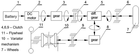
Figure 1.
Structural diagram.

Figure 2.
Block diagram.
3. Control Algorithms and Solutions
3.1. Initial Charging of KERS with Energy
The direction of the energy flow in accordance with Figure 2 is from the electric motor to the flywheel in the sequence 1-2-3-4-5-8-9-10-11, with clutches 4 and 9 and brake 6 engaged.
To the axis of the engine, the equation of motion has the following form:
Figure 3 and Figure 4 present the graphs of the static characteristic of the engine and the angular velocity of the flywheel as a function of time.
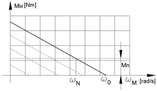
Figure 3.
Motor’s static characteristic.
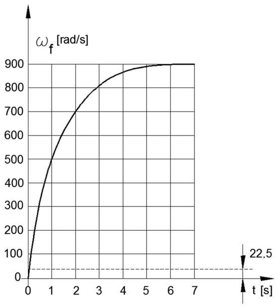
Figure 4.
Flywheel’s angular velocity.
3.2. Motion of the Vehicle by Electric Motor
The flow of the energy direction is in the sequence 1-2-3-4-5-6-7 (Figure 2), with couplings 4 and 6 switched on and coupling 10 switched off. The differential equation of motion for the driving wheels takes the following form:
where Mc1 = m g f/i1; Mc2 = h S rw3 ωm 2/i12; and V = rw ωm/i1.
Figure 5 and Figure 6 show the changes in the angular velocity of the motor’s rotor, and the dynamic characteristic of the engine as a function of time.
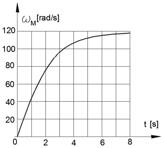
Figure 5.
Velocities ωm.
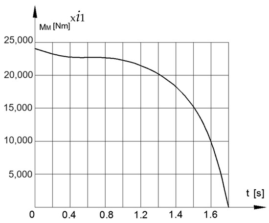
Figure 6.
Engine’s dynamic moment.
3.3. Stopping Process
For charging with energy from the kinetic recovery system, the direction of energy flow is in the sequence 7-6-5-8-9-10-11 (Figure 2), with brake 4 and clutches 6 and 9 engaged.
The differential equation of motion of the electric vehicle, brought to the axis of drive wheels 7 (Figure 2), is derived using the Lagrange equation of the second kind [21]. The kinetic energy of the vehicle has the following form:
where .
The generalized force in the right-hand side has three components: moments, reduced by losses in the flywheel and in the variator (CVT), and the road resistances. This can be depicted as follows:
where .
After finding the derivatives of energy (3) with respect to phi φ, omega ωw, and time t, the differential equation of the transmission ratio iV of the variator (CVT) acquires the following form:
where .
If the following assumptions are made
then differential Equation (5) is reduced to a linear equation with variable coefficients relative to the square of the transmission function of the variator (CVT) of the type
whose solution has the form
at t = 0; ωw = 103 [1/s] and ω*= 0 [1/s2].
By test function ωw= 103–0.25. t2 (103 ≥ ωw ≥ 3), the solutions of Equation (8) are presented in Figure 7 for iV(t) and in Figure 8 for ωf(t) as functions of time.
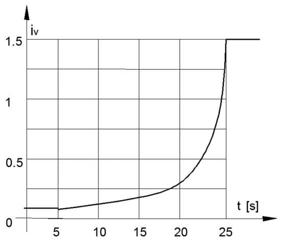
Figure 7.
Transmission ratio of CVT in stopping mode.
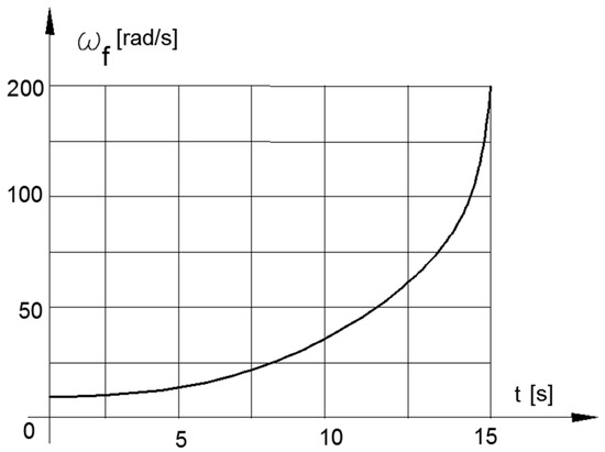
Figure 8.
Angular velocity of the flywheel in stopping mode.
3.4. Accelerating the Vehicle from (KERS) Kinetic Storage System
The direction of the energy flow in accordance with Figure 2 is in the sequence 11-10-9-8-5-6 and 7, with clutches 6 and 9 and brake 4 engaged.
The differential equation describing the behavior of the variator (CVT) as a function of time is the same (6), but under a different initial condition where t = 0; ωw = 3 [1/s]; and ωw∗ = 0.175 [1/s2]. The high friction coefficient of 0.7 in the variator mechanism is provided by the applied nanostructure multilayer (AlTiN) ml.
The test function constitutes a positive gradient () and changes in (4), where the coefficients of efficiencies have degrees in the power of −1 or (ηi−1).
The solutions of Equation (8) for this case are presented in Figure 9 for iV(t) and for angular velocity of the flywheel ωf(t), and in Figure 10 for ωf(t) as functions of time.
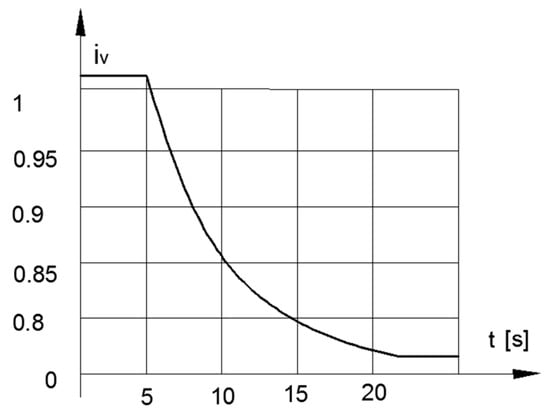
Figure 9.
Transmission ratio of the CVT in acceleration mode.
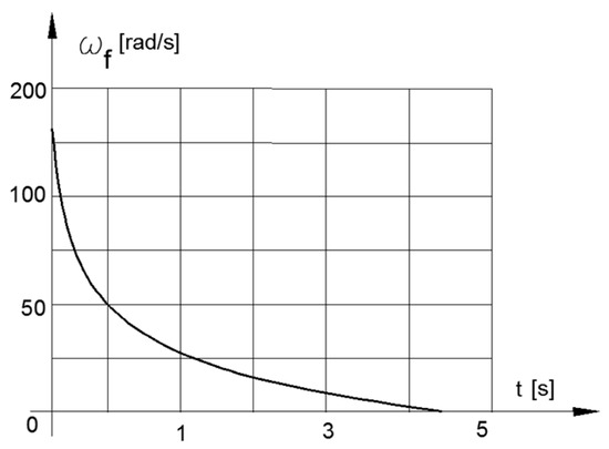
Figure 10.
Angular velocity of the Flywheel in acceleration mode.
3.5. Accelerating the Vehicle (Split)
The following is for driving the electric vehicle simultaneously from the motor and the flywheel. The directions of the energy flows are in the following sequence, simultaneously—1-2-3-4-5, 11-10-9-8-5-6-7—with clutches 4, 6, and 9 engaged.
The kinetic energy of the electro-mechanical system of the electric vehicle in split drive with respect to the drive wheels is represented by
where .
The reduced moment of the active forces has the form
where M is the dynamic characteristic (moment) of the engine and n is a number depending on the gear ratios i1, i2, and iD, with efficiencies of the degree of +1 or −1 depending on the direction of the energy flow.
The dynamic characteristic of the DC electric motor is represented with one time constant T, which is represented by the following first-order differential equation:
which is analogical of the second equation of (2), where Fr is equal to and and reduced external force is .
After successively calculating the derivatives of the kinetic energy (9) with respect to position, velocity, and time and substituting in the Lagrange equation and known transformations, we arrive at the following systems of differential Equations (11) and (12):
where
The differential equation above in relation to the transmission ratio of the variator (CVT) has variable coefficients and does not have an analytical solution. It has a physical meaning with known V and V⃰ values
From the analysis of the numerical values in front of the derivatives in the system of Equations (12) and (13), it can be easily established that this system belongs to the so-called “stiff” from mathematical equations point of view. The difference in the orders of this value reaches three. For this reason, the numerical solutions were obtained using special methods [22,23].
The computer simulations were performed on a digital array of the standardized transport cycles NEUDC and WLTC-3 (Figure 11 and Figure 12).
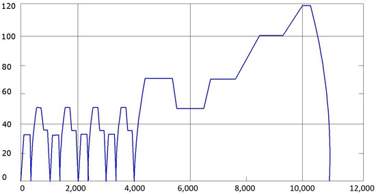
Figure 11.
NEUDC cycle.
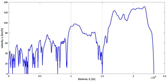
Figure 12.
WLTC 3 cycle.
The results of the numerical solutions of the system differential Equations (11) and (12) for the angular velocities of the flywheel within the durations of the aforementioned transport cycles are presented in Figure 13 and Figure 14.
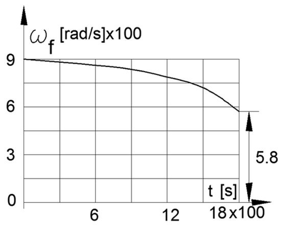
Figure 13.
ωf by NEUDEC cycle.
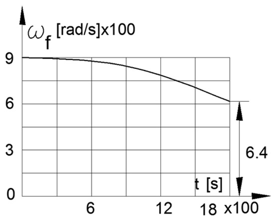
Figure 14.
ωf by WLTC 3 cycle.
4. Conclusions
An innovative structure and algorithm [24] for controlling a hybrid urban electric vehicle with a kinetic energy storage system are proposed, satisfying the set goals:
- Elimination of shock loads on the electric battery during the stopping of the vehicle;
- A single transformation from electrical to mechanical energy;
- The possibility of increasing the mileage/range of the electric vehicle with a single charge of the electric battery is preserved.
The efficiency, reliability, and security of the proposed algorithm for controlling the energy flows between the electric motor and the kinetic energy storage system are proven.
5. Patents
A corresponding utility model has been developed with the name “System for hybrid electric vehicle propulsion with kinetic energy accumulator” and respective number BG/U/2025/6462 [24].
Author Contributions
Conceptualization, V.J. and K.S.; methodology, V.J.; data curation, K.S.; writing—original draft preparation, V.J.; writing—review and editing, K.D.; funding acquisition, K.D. All authors have read and agreed to the published version of the manuscript.
Funding
This work has been accomplished with financial support from the European Regional Development Fund within the Operational Program “Bulgarian national recovery and resilience plan”, the procedure for the direct provision of grants “Establishing of a network of research higher education institutions in Bulgaria”, and under Project BG-RRP-2.004-0005 “Improving the research capacity and quality to achieve international recognition and resilience of TU-Sofia (IDEAS)”. The equipment used in the study was financed by the European Regional Development Fund under “Research Innovation and Digitization for Smart Transformation” program 2021-2027 under the Project BG16RFPR002-1.014-0006 “National Centre of Excellence Mechatronics and Clean Technologies”.
Institutional Review Board Statement
Not applicable.
Informed Consent Statement
Not applicable.
Data Availability Statement
The data presented in this study are available upon request from the corresponding author.
Conflicts of Interest
The authors declare no conflicts of interest.
References
- Cole, D. The Effectiveness of Energy Storage in Transport Applications. Master’s Thesis, University of the West of England Repository, Bristol, UK, 2016. Available online: https://uwe-repository.worktribe.com/preview/886490/Thesis%20Final%20for%20upload%20with%20photo%20redacted%2022_6_17.pdf (accessed on 26 November 2025).
- Rabenorst, D. Super-flywheel Energy Storage. In Wind Energy Conversion System; Workshop Washington NASA TM-X-69786; National Aeronautics and Space Administration: Washington, DC, USA, 1983. [Google Scholar]
- Lafos, M.; Calero, J.; Garcia-Tabares, L.; Ugena, D.; Portillo, S.; Vazquez, C.; Gutierrez, J.; Tobajas, C.; Martinez, J.; Lucas, J.; et al. Kinetic Storage for Railway Substations. In Proceedings of the ACE-2 System Proceedings of EESAT, San Francisco, CA, USA, 23–26 September 2007. [Google Scholar]
- Todorov, G.; Kamberov, K.; Ivanov, A. Decreasing power loss through control improvement of kinetic UPS system. In Proceedings of the 44th International Conference on Applications of Mathematics in Engineering and Economics: (AMEE’18), Sozopol, Bulgaria, 8–13 June 2018. [Google Scholar]
- CEC-500-2019-012; Flywheel Systems for Utility Scale Energy Storage. California Energy Commission: Sacramento, CA, USA, 2019.
- Fraunhofer Institute for Transportation and Infrastructure Systems IVI. Institute Report 2022 (English). Fraunhofer IVI. 2022. Available online: https://www.ivi.fraunhofer.de/content/dam/ivi/en/documents/institutereport/JB_2022_en.pdf (accessed on 28 September 2024).
- Beacon Power. Available online: http://www.beaconpower.com/ (accessed on 10 June 2025).
- Independent Automedia News Website. Available online: https://automedia.investor.bg (accessed on 20 March 2025).
- Independent Motorsport News Website. Available online: https://www.racefans.net (accessed on 1 May 2009).
- Daberkow, A.; Ehlert, M.; Kaise, D. Electric car operating and flywheel Storage. In Conference on Future Automotive Technology; Lienkamp, M., Ed.; Springer: Wiesbaden, Germany, 2013; pp. 19–30. [Google Scholar]
- Press Release. Available online: https://thebrakereport.com/volvo-using-kers-on-production-cars-in-2020/ (accessed on 17 November 2020).
- Van Berkel, K.; Rullens, S.; Hofman, T.; Vroemen, B.; Steinbuch, M. Analysis of optimal mechanical-hybrid powertrain topologies. In Proceedings of the Workshop on Engine and Powertrain Control Simulation and Modeling, IFAC, Rueil-Malmaison, France, 30 November–2 December 2012; pp. 23–25. [Google Scholar]
- Jivkov, V.; Draganov, V.; Stoyanova, Y. Electric Vehicles Mileage Extender Kinetic Energy Storage. J. Theor. Appl. Mech. 2015, 45, 17–38. [Google Scholar] [CrossRef]
- Kok, D.; Van Der Graaf, R.; Kriens, R. Validation of high efficiency flywheel hybrid driveline concept. In Engineering Challenge; Human Friendly Vehicles Proceedings XXVI Word Automotive Congress FISITA 96, Prague, Czech Republic, 17–21 June 1996; FISITA: Bishop’s Stortford, UK, 1996. [Google Scholar]
- Frank, A.; Beachley, N. Evaluation of the Flywheel Drive Concept for Passenger Vehicles; SAE Technical Paper 790049; JSTOR: New York, NY, USA, 1979; pp. 230–241. [Google Scholar]
- Maschinenfabrik Oerlikon MFO. Swiss Patents Nos. CH242086 (Filed 19 July 1944; Published 15 April 1946). Available online: https://patents.google.com/patent/CH242086A/de?oq=CH242086 (accessed on 28 January 2026).
- Maschinenfabrik Oerlikon MFO. Swiss Patents Nos. CH244759 (Filed 19 July 1944; Published 15 April 1946). Available online: https://patents.google.com/patent/CH244759A/de?oq=CH244759+ (accessed on 28 January 2026).
- Porsche, A.G. Porsche 911 GT3 R Hybrid—The First Hybrid Racing Car from Porsche. Porsche Press Release. 2010. Available online: https://newsroom.porsche.com/en/motorsports/porsche-powered-by-two-hearts-performance-hybrid-vehicles-13618.html? (accessed on 28 January 2026).
- Amenta-Deu, C.; Cortes, H. Analysis of KERS in Electric Vehicles. Vehicles 2023, 5, 387–403. [Google Scholar] [CrossRef]
- Jivkov, V.; Draganov, V. Theoretical Study and Experimental Validation of a Hydrostatic Transmission Control for a City Bus Hybrid Driveline with Kinetic Energy Storage. Energies 2018, 11, 2200. [Google Scholar] [CrossRef]
- Lurie, A. Analytical Mechanics. M. Physmathgiz. Available online: http://www.teormeh.net/Zhilin_New/pdf/Zhilin_Lurie_rus.pdf (accessed on 20 January 2026).
- Kozar, M.; Plovanić, M.; Sulovsky, T. Derivation matrix in Mechanics—Data approach. Eng. Rev. 2023, 43, 1–8. [Google Scholar] [CrossRef]
- Forsait, T. Machine’s Methods for Mathematical Calculation; House “Pease”: Moscow, Russia, 1974. [Google Scholar]
- Jivkov, V.; Stoichkov, K. Hybrid Electric Vehicle Propulsion System with Kinetic Energy Storage. BG/U/2025/6462, 10 June 2025. submitted. [Google Scholar]


Disclaimer/Publisher’s Note: The statements, opinions and data contained in all publications are solely those of the individual author(s) and contributor(s) and not of MDPI and/or the editor(s). MDPI and/or the editor(s) disclaim responsibility for any injury to people or property resulting from any ideas, methods, instructions or products referred to in the content. |
© 2026 by the authors. Licensee MDPI, Basel, Switzerland. This article is an open access article distributed under the terms and conditions of the Creative Commons Attribution (CC BY) license.