Abstract
A removable module design is proposed to enable the use of open wagons for container transport. It acts as an intermediate adapter between an open wagon body and a tank container, ensuring the possibility of their reliable interaction. The dynamic loading of its structure was determined to substantiate the proposed scheme of tank container transport on an open wagon. A mathematical model characterizing the longitudinal load of a tank container placed on an open wagon was developed for this purpose. The determined accelerations acting on the tank container were considered when studying its strength. It was established that, considering the proposed fastening scheme, the maximum stresses occurring in the tank container structure are lower by 21.8% than the permissible ones. Therefore, the strength of the tank container is ensured. Accelerations acting on an open wagon body and a tank container were determined and considered when studying their strength. It was found that the maximum stresses occurring in the open wagon body and the tank container, considering the proposed fastening scheme, are lower than the permissible ones. Therefore, the strength of their structures is ensured. The research conducted will contribute to increasing the efficiency of tank container transport by rail and, therefore, container transportation in general.
1. Introduction
Railway transport is supposed to be the most effective means of land transport of passengers [1] and cargo in many countries. Railway lines connect cities and towns not only within one country [2], but also between two or more countries on continents [3]. When railway vehicles powered by electric traction operates on these lines, the negative effects of the exhaust emissions of rail vehicle operation are minimized [4]. Railway transport manifests its advantages mainly in the field of cargo transport. Freight wagons are connected to long trainsets with several tens of wagons. Then, these trainsets have lower drag, rolling resistance and even higher running speeds in comparison with road vehicle-trailer combinations. Moreover, freight wagons have higher axleloads [5], and the operational safety is supposed to be higher in comparison with road transport [6,7,8,9]. Furthermore, the infrastructure needed for railway transport includes water-permeable subsoil and narrower built-in width, which is more friendly to the environment than the asphalt of concrete roads [10,11,12,13]. On the other hand, it is not possible to deliver cargo door-to-door by railway, and the efficiency of smaller shipments by them is lower [14,15]. Therefore, the intermodal transport of cargo has recently become very popular. It means that the cargo is loaded in one transport unit, and this unit is handled and manipulated by a proper machine to place it on a wagon, a semi-trailer, or a ship.
Container transportation is one of the most common types of cargo transportation in international traffic and an intermodal transportation system [16,17]. This can be explained by the fact that the container is a mobile transport means. Currently, a fairly wide range of cargo is transported in containers, a significant segment of which is bulk cargo. Tank containers are used for transportation.
Transportation of tank containers by rail is carried out on flat wagons equipped with fitting stops. The shortage of flat wagons in operation necessitates the adaptation of other types of wagons for the transportation of tank containers. Such a wagon can be an open wagon. The absence of a roof allows its use for container transportation. At the same time, the design of the open wagon is not adapted for the reliable fastening and transportation of tank containers by rail. Therefore, there is a need to create solutions aimed at involving open wagons in container transportation.
2. Analysis of Recent Research and Publications
The issues of determining the dynamic load capacity, strength, and improvement of tank containers to increase the efficiency of their operation are quite widespread. Thus, the strength of a 40-foot tank container with an improved frame design under the main operating load conditions was investigated in the publication [18]. It was established based on the analysis that the strength of the improved tank container design is maintained.
The features of numerical optimization of the tank container frame to reduce its material consumption are highlighted in the paper [19]. The results of the calculations made it possible to formulate recommendations for optimizing the tank container while ensuring the strength of its design in operation. However, it should be noted that the authors of the papers [18,19] did not investigate the possibility of transporting this tank container design in an open wagon when conducting the relevant calculations.
Publication [20] is devoted to the study of the strength of a tank container for the transportation of food products under operational conditions. The authors of the publication conducted a numerical analysis of the tank container, identified the most-loaded zones of its structure, and performed a modal analysis. The achieved results were compared with the experimentally achieved results. Recommendations for the operation of this tank container are given. The disadvantage of this study is that the authors did not study through calculations the possibility of transporting this tank container in an open wagon.
A solution for improving the tank container frame to ensure its strength in operation is proposed in work [21]. At the same time, the authors proposed to supplement the frame with a reinforcing element that provides partial unloading of the area of interaction of the paw with the lower corner fittings to reduce the longitudinal loading of the tank container. The corresponding justification for such an improvement is given. However, the authors limited themselves to studying the stress state of a tank container only when it is subjected to longitudinal loads on its structure during transportation by a flat wagon.
The features of the strength analysis of a tank container when perceiving dynamic loads while moving in a train are highlighted in the article [22]. A tank container of the standard size 1AA was chosen as a prototype. The results of the stress analysis of the tank container structure from dynamic loads acting on it are presented.
The authors of the paper [23] proposed improving its design to improve the strength of the tank container in operation. At the same time, three options for improving the tank container frame were considered. The corresponding calculations were made on the strength of the tank container during rail transportation. The achieved results established that an improved frame has a minor effect on the strength of the boiler. At the same time, the authors of the papers [22,23] did not propose solutions to increase the efficiency of tank container operation.
The features of determining dynamic loads on the tank container structure for transporting vegetable oils are studied in the publication [24]. At the same time, the authors conducted experimental studies of dynamic loads on a tank container placed on a flat wagon during a shunting collision. It was found that the accelerations obtained are within the permissible limits. Therefore, the proposed structural solutions in the tank container are appropriate. However, the authors of this publication, as well as in the work [21], considered only one loading mode of the tank container.
The publication [25] highlights the features of the fatigue strength analysis of a tank container for liquefied gases of the size 1 AA. The studies were carried out in the ANSYS software package (version 2023). It was established based on the calculations that the durability of the proposed tank container design is 20 years. At the same time, the authors did not study the issue of increasing the efficiency of the transportation of this tank container design by rail.
The analysis of the literature sources proves that the issues of improving tank containers are relevant. However, it is important to study the possibility of their transportation in open wagons in the event of a shortage of flat wagons to increase the efficiency of their operation. In this regard, the purpose of this study is to determine the loading of a tank container considering the improved fastening scheme in the open wagon during operational modes. This goal was achieved by solving the following problems:
- To conduct mathematical modeling of the dynamic loading of a tank container, considering the proposed fastening scheme on an open wagon;
- To calculate the strength of the open wagon body when tank containers are transported on it, considering the proposed interaction scheme;
- To determine the strength indicators of a tank container when transported on an open wagon.
3. Materials and Research Methods
Fitting stops are installed on the floor of the open wagon (Figure 1) to secure tank containers.
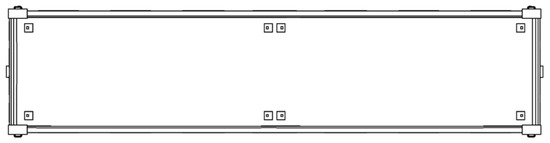
Figure 1.
Placements of fitting stops on the open wagon.
Calculations of the open wagon body were carried out in order to determine the strength of its structure, considering its modernization. The calculations were implemented using the finite element method in the SolidWorks Simulation software package (version 2024). A spatial model of the open wagon supporting structure with fitting stops was created for this purpose based on the relevant drawings.
When drawing up the calculation scheme of the wagon body, it was considered that it experiences a vertical load from the weight of containers placed at Pv (Figure 2). The longitudinal dynamic load acting on the fitting stop from the fitting Pp was also considered. A longitudinal load Pup was applied to the front stops of the automatic coupler. The magnitude of the longitudinal load was taken to be equal to 2.5 MN. This means that the loading mode of movement of the open wagon in a train was simulated, known as “jerk” [26].
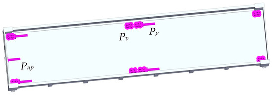
Figure 2.
A calculation diagram of the open wagon.
A finite element model (FE model) of the open wagon body is formed by tetrahedra and it is depicted in Figure 3.
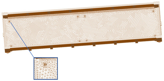
Figure 3.
A finite element model of the open wagon body.
The largest tetrahedral size was 80 mm, and the smallest one was 16 mm. The FE model consisted of 93,163 nodes and 280,205 elements. The calculation was performed assuming that the body was made of 09G2S steel (Table 1).

Table 1.
The main characteristics of steel marked 09G2S.
The boundary conditions (fastening of the body model) are shown in Figure 4. The body model was fixed by the studs. The friction forces between the studs and the thrust washers were not considered [27].
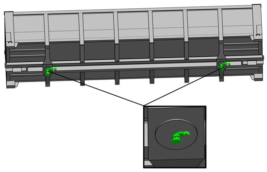
Figure 4.
The boundary conditions of the open wagon body.
The HMH hypothesis (von Misses criterion) was considered in the calculations. The results of the calculations are shown in Figure 5 and Figure 6. It was established that the maximum stresses arise in the fitting stops and they are equal to the value of 142 MPa (Figure 5). These stresses do not exceed the permissible values. The maximum displacements arise in the areas where the fitting stops are located behind the center of the body, and they are 4.2 mm (Figure 6).
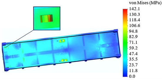
Figure 5.
A distribution of stresses in the open wagon body.
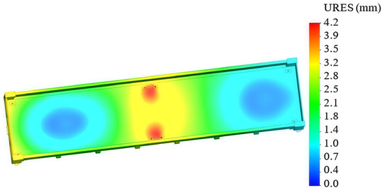
Figure 6.
Displacements of the open wagon body.
The calculations show that the transportation of containers using the specified fastening scheme is allowed. However, in a case when the dynamic load acting on the container exceeds the friction force between the fittings and the fitting stops, the stresses acting on them are higher than permissible values. Therefore, a solution was proposed for the technical adaptation of open wagons for the transportation of containers using a removable module (Figure 7). This module works on the principle of an intermediate adapter between the container and the open wagon body.
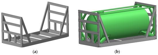
Figure 7.
The removable module for fastening containers: (a) a perspective view; (b) loaded with a tank container.
The load on the floor of the open wagon from the container, in this case, would not be transmitted at four points. However, this load is transmitted along the area where the module fits to the floor (Figure 8, indicated by gray color).
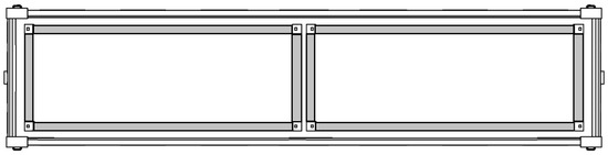
Figure 8.
The area of interaction of the removable module with the floor of the open wagon.
In addition, the use of a removable module limits the movement of the container in the longitudinal plane. This movement can occur due to the presence of a technological gap between the fitting and the fitting stop. The design of the removable module is designed in such a way that the fittings have recesses. Due to this, the vertical walls of the fitting stop interacting with the walls of the profile of the removable module (Figure 9). The container is fixed in the removable module through the fitting stop, 3, installed on the longitudinal beam, 4, of the removable module.
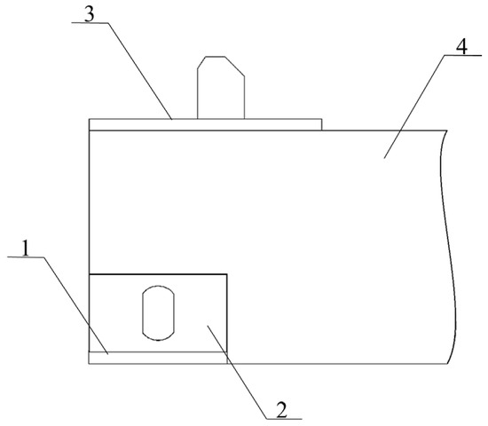
Figure 9.
Interaction of the fitting of the removable module with the fitting stop: 1—fitting stop on an open wagon; 2—fitting; 3—fitting stop of the removable module; 4—longitudinal beam of the removable module.
The placement of tank containers on an open wagon using the proposed scheme of their interaction is shown in Figure 10.
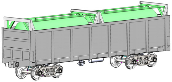
Figure 10.
The placement of tank containers on the open wagon.
The loading of tank containers is supposed to be carried out, provided that they are placed in removable modules. In this case, suspensions or other lifting and transport equipment are used to move (load–unload) removable modules with tank containers onto or out of the open wagon.
The removable module, considering its modernization, can be used as a modular vehicle for the transportation of various types of cargo. This increases its demand in operation.
Strength calculations were performed to determine the strength of the open wagon body, considering this scheme of securing containers on it. The finite element method was used. These calculations were performed in SolidWorks Simulation software. The open wagon model 12-295 was chosen as a prototype.
The design scheme of the open wagon is shown in Figure 11. It considers the vertical load Pv, which is distributed over the area of contact of the removable module with the open wagon floor, as well as the longitudinal load Pp, which acts on the plates of the fitting stops. A longitudinal force of 3.5 MN was applied to the rear stop of the automatic coupler of the open wagon (it is not shown in Figure 11). This force was balanced by the inertia forces of the wagon mass on the opposite side of the body.
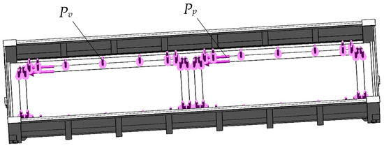
Figure 11.
A calculation scheme of the open wagon.
The FE model of the open wagon body is formed by tetrahedra. This model has 370,146 elements with a maximum size of 100 mm and a minimum of 20 mm. The number of nodes of the model was 122,058.
A mathematical simulation of the dynamic loading of the open wagon body loaded with two tank containers was carried out to determine the longitudinal load Pn.
Since the removable modules and tank containers do not have their own degree of freedom on the open wagon, they are considered to be masses attached to it. The bulk cargo placed in a boiler of the tank container is considered a pendulum. Then, the calculation scheme of the open wagon has the form shown in Figure 12.
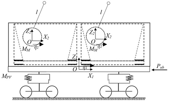
Figure 12.
A calculation scheme of the open wagon.
The mathematical model (Equation (1)) derived by means of Lagrange’s equations of the second kind and describing the movement in the system “open wagon with a removable module–tank container–bulk cargo” consists of two differential equations and it has the following form:
where MPV [kg] is the gross mass of the open wagon, Pub [N] is the force acting on the automatic coupler, MM [kg] is the mass of the pendulum, which simulates the movement of bulk cargo in the tank container, l [m] is the length of the pendulum suspension, INV [kg∙m2] is the moment of inertia of the pendulum and q1, q2 are the generalized coordinates that determine the movement of the open wagon and bulk cargo in the tank container boiler relative to the longitudinal axis, respectively. It is considered that the generalized coordinates have the same angular displacement.
The solution of this mathematical model was carried out in the MathCad software, version 2022 [28,29,30,31,32,33]. It was reduced to the form:
where Z = rkfixed(Y0, tn, tk, n, T).
At the same time: y1 = q1, y2 = q2, , .
Generalized accelerations are calculated using the arrays ddqj,i:
It is assumed that the tank containers are filled with gasoline using 95% of the volume of their boilers. The magnitude of the longitudinal force on the automatic coupler is assumed to be 3.5 MN [26]. The initial conditions were set to zero. The magnitude of the acceleration acting on the tank container, considering these assumptions, was about 37 m/s2 and on the open wagon it was about 36.4 m/s2.
4. Research Results and Discussion
The acceleration determined by the mathematical model was considered when calculating the strength of the open wagon body. The results of the calculations are shown in Figure 13 and Figure 14. The maximum stresses in the body were identified in the zone of interaction of the backbone beam with the pivot beam. These stresses amounted to 304.4 MPa (Figure 13), which is lower by 2% than the permissible ones. The stresses that arise in the zone of interaction of the open wagon body floor amounted to about 165 MPa.
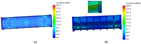
Figure 13.
A distribution of stresses in the open wagon body: (a) a top view; (b) a bottom view.
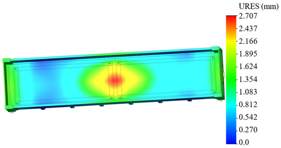
Figure 14.
Displacements in the nodes of the open wagon body.
The maximal displacements occur in the middle part of the body, and they are 2.7 mm (Figure 14).
Due to the fact that such a method of transporting tank containers has not been used before, the strength of the tank container structure was determined as part of this study. It is important to note that the direction of the loads acting on the tank container during transportation in the open wagon is identical to that acting during transportation by a platform wagon. However, the numerical values of these loads are not currently regulated by existing regulatory documents, since such a transportation scheme is new. This justifies the need for the specified calculation.
The calculation was carried out using an example of a tank container of the standard size 1CC and model TK25. Based on this model, a finite element model was formed using tetrahedra [34, 35, 36, 37, 38]. The model includes 172,114 elements with a maximum size of 120 mm and a minimum size of 24 mm (Figure 15). The number of nodes in the model was 56,913. At the next stage of the study, a calculation scheme of a tank container was created (Figure 16). It was considered that the tank container is subjected to the vertical load PV [N] due to the gross weight, the load due to pressure from the bulk cargo on the boiler PNV [N], the longitudinal force PP [N] from the bulk cargo on the bottom of the boiler, and finally the forces PF [N] acting on the fittings.
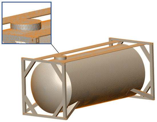
Figure 15.
A finite element model of the tank container.
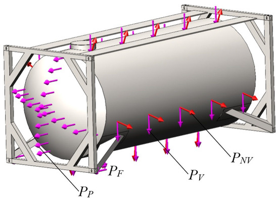
Figure 16.
The tank container design diagram.
The pressure PNV acting on the boiler from the bulk cargo is calculated using the following well-known formula:
where ρ [kg/m3] is the density of the bulk cargo, h [m] is the height of the bulk cargo distribution relative to the boiler, and g [m/s2] is gravitational acceleration.
The value of the longitudinal force PP from the bulk cargo on the bottom of the boiler is calculated by the following formula:
where Pub [N] is the longitudinal force acting on the automatic coupler, mv [kg] is the mass of the bulk cargo, mbr [kg] is the gross mass of the tank container, and Fk [N] is the cross-sectional area of the boiler.
The tank container was secured to the fittings using a rigid connection. It was found that, considering the calculations, the maximum stress occurs in the area of the hatch, and it has a value of 242.9 MPa (Figure 17). The resulting stress does not exceed the permissible value, which is assumed to be 310.5 MPa [26].
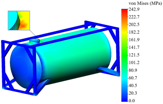
Figure 17.
A stressed state of the analyzed tank container.
The maximum displacements were identified at the end part of the boiler and amounted to 1.45 mm (Figure 18).
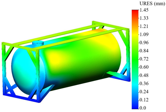
Figure 18.
Displacements in the tank container nodes.
The calculations show that the strength of the tank container is maintained considering the proposed fastening scheme. At the same time, the stresses in the structure are lower by 17% than those that occur when using a typical scheme for transporting tank containers in operation.
The disadvantage of this study is that the computational model of the tank container for strength calculation does not consider welds. Hence, the tank container structure is considered monolithic. The limitation of the study is that the proposed procedure for determining the loading of the tank container during rail transportation considers only the perception of longitudinal loads by the structure. This is explained by the fact that these loads have the greatest impact on the strength of the tank container.
This study has certain advantages compared to previous ones. For example, unlike works [18,19], the authors proposed solutions that allow the transportation of tank containers in open wagons, which increases the efficiency of their operation. Works [20,21] did not study the loading of a tank container under the condition of transportation on an open wagon. The authors of works [22,23,24,25] did not propose solutions to increase the efficiency of the operation of tank containers by involving open wagons in their transportation.
The development of this study is the determination of the tank container loading considering different amounts of underfilling of the boiler with bulk cargo. Moreover, attention needs to be paid to the issue of studying the tank container loading under other operational load schemes. The authors also plan to study the possibility of transporting containers in open wagons with a 1435 mm track gauge. In such a case, European standards will be considered [39].
The studies conducted will contribute to increasing the efficiency of tank container transportation by rail and, therefore, container transportation in general.
5. Conclusions
- A mathematical model of the dynamic load of an open wagon loaded by tank containers was carried out, considering the proposed fastening scheme. It was established that under the condition of 95% loading of the boiler with bulk cargo and the action of a force of 3.5 MN on the open wagon coupler, the accelerations acting on the tank container were about 37 m/s2, and on the open wagon about 36.4 m/s2.
- The strength of the open wagon body when transporting tank containers in it was calculated, considering the proposed interaction scheme. The maximum stresses in the open wagon body arise in the interaction zone of the backbone beam with the pivot beam. And they are 304.4 MPa. The obtained stresses are lower than the permissible ones by 2%. The stresses that arise in the interaction zone of the floor with the body were about 165 MPa. The maximum displacements arise in the middle part of the body and are 2.7 mm.
- The strength indicators of the tank container during transportation on an open wagon were determined. The results of the calculations showed that the maximum stress occurs in the area of the hatch of the tank container boiler and is 242.9 MPa. It should be noted that the stress value obtained is lower than the permissible one by 21.8%. Thus, the strength of the tank container, considering the proposed fastening scheme on an open wagon, is ensured. The maximum displacements were indicated at the end part of the boiler and amounted to the value of 1.45 mm.
Author Contributions
Conceptualization, A.L., J.G. and J.D.; methodology, A.L., J.G. and J.D.; software, A.L., J.D. and P.R.; validation, J.G. and J.D.; formal analysis, A.L. and J.D.; investigation, A.L. and J.D.; resources, A.L. and J.D.; data curation, A.L., J.G. and P.R.; writing—original draft preparation, A.L.; writing—review and editing, J.D.; visualization, A.L. and J.D.; supervision, J.G.; project administration, J.G., J.D. and P.R.; funding acquisition, A.L., J.G. and J.D. All authors have read and agreed to the published version of the manuscript.
Funding
This publication was supported by the Cultural and Educational Grant Agency of the Ministry of Education of the Slovak Republic under the project KEGA 031ŽU-4/2023: Development of key competencies of the graduates of the study program Vehicles and Engines. This research was supported by the Slovak Research and Development Agency of the Ministry of Education, Science, Research and Sport of the Slovak Republic VEGA 1/0308/24 “Research of dynamic properties of rail vehicles mechanical systems with flexible components when running on a track”. “Funded by the EU NextGenerationEU under the Recovery and Resilience Plan for Slovakia under the project No. 09I03-03-V01-00131”.
Institutional Review Board Statement
Not applicable.
Informed Consent Statement
Not applicable.
Data Availability Statement
The data is contained within the article.
Conflicts of Interest
The authors declare no conflicts of interest.
References
- Kučera, P.; Heřmánková, A. The use of automation in rail transport to ensure interchanges in regional passenger transport. Commun.-Sci. Lett. Univ. Zilina 2024, 26, D82–D91. [Google Scholar] [CrossRef]
- Akgun, N.; Campisi, T.; Talha Sunar, M. Generalized ordered logit model with testing assumptions: A case study of using urban light rail in Bursa. Commun.-Sci. Lett. Univ. Zilina 2024, 26, D38–D51. [Google Scholar] [CrossRef]
- Mindur, M.; Mindur, L. The influence of the selected international organizations on the development of transport. Sci. J. Sil. Univ. Technol. Ser. Transp. 2023, 119, 171–187. [Google Scholar] [CrossRef]
- Fischer, S.; Kocsis Szürke, S. Detection process of energy loss in electric railway vehicles. Facta Univ. Ser. Mech. Eng. 2023, 21, 81–99. [Google Scholar] [CrossRef]
- Kruhan, D.; Kovalskyi, D. Quasi-static methods for determining the calculated wheel load on the railway track. Acta Tech. Jaurinensis 2025, 18, 38–45. [Google Scholar] [CrossRef]
- Jover, V.; Fischer, S. Statistical analysis of track geometry parameters on tramway line No. 1 in Budapest. Balt. J. Road Bridge Eng. 2022, 17, 75–106. [Google Scholar] [CrossRef]
- Juricka, M.; Fojtl, L.; Rusnáková, S.; Juřičková, E. Acoustic characteristics of composite structures used in train. Manuf. Technol. 2020, 20, 335–341. [Google Scholar] [CrossRef]
- Tomaschek, T.A.; Selmeczy, A.M. Mobility data for a safer and greener transport. Acta Tech. Jaurinensis 2023, 16, 129–142. [Google Scholar] [CrossRef]
- Rosić, S.; Stamenković, D.; Banić, M.; Simonović, M.; Ristić-Durrant, D.; Ulianov, C. Analysis of the safety level of obstacle detection in autonomous railway vehicles. Acta Polytech. Hung. 2022, 19, 187–205. [Google Scholar] [CrossRef]
- Fischer, S. Investigation of the settlement behavior of ballasted railway tracks due to dynamic loading. Spectr. Mech. Eng. Oper. Res. 2025, 2, 24–46. [Google Scholar] [CrossRef]
- Ezsias, L.; Kozma, K.; Tompa, R.; Fischer, S. Crushed stone supply challenges for infrastructure development in Hungary. Nauk. Visnyk Natsionalnoho Hirnychoho Univ. 2024, 6, 28–37. [Google Scholar] [CrossRef]
- Fischer, S.; Harangozó, D.; Németh, D.; Kocsis, B.; Sysyn, M.; Kurhan, D.; Brautigam, A. Investigation of heat-affected zones of thermite rail welding. Facta Univ. Ser. Mech. Eng. 2024, 22, 689–710. [Google Scholar] [CrossRef]
- Matej, J.; Seńko, J.; Caban, J.; Szyca, M.; Gołȩbiewski, H. Influence of unsupported sleepers on flange climb derailment of two freight wagons. Open Eng. 2024, 14, 20220544. [Google Scholar] [CrossRef]
- Kostrzewski, M.; Abdelatty, Y.; Eliwa, A.; Nader, M. Analysis of modern vs. conventional development technologies in transportation—The case study of a last-mile delivery process. Sensors 2022, 22, 9858. [Google Scholar] [CrossRef] [PubMed]
- Petrović, A.D.; Banić, M.; Simonović, M.; Stamenković, D.; Miltenović, A.; Adamović, G.; Rangelov, D. Integration of computer vision and convolutional neural networks in the system for detection of rail track and signals on the railway. Appl. Sci. 2022, 12, 6045. [Google Scholar] [CrossRef]
- Gerlici, J.; Lovska, A.; Vatulia, G.; Pavliuchenkov, M.; Kravchenko, O.; Solcansky, S. Situational adaptation of the open wagon body to container transportation. Appl. Sci. 2023, 13, 8605. [Google Scholar] [CrossRef]
- Lee, C.Y.; Song, D.P. Ocean container transport in global supply chains: Overview and research opportunities. Transp. Res. Part B Methodol. 2017, 95, 442–474. [Google Scholar] [CrossRef]
- Purnamasari, D.; Tuswan, T.; Muttaqie, T.; Sandjaja, I.E.; Machfudin, A.; Rizal, N.; Alif Rahadi, S.J.; Sasmito, A.; Zakki, A.F.; Mursid, O. Structural assessment of 40 ft mini LNG ISO tank: Effect of structural frame design on the strength performance. Curved Layer. Struct. 2024, 11. [Google Scholar] [CrossRef]
- Tuswan, T.; Andrian, M.; Amiruddin, W.; Muttaqie, T.; Sari, D.S.; Bisri, A.; Yuniati, Y.; Soetarjo, M.; Utina, M.R.; Harmadi, R. Design improvement using topology optimization for the structural frame design of a 40 Ft LNG ISO container tank. Designs 2024, 8, 21. [Google Scholar] [CrossRef]
- Liguori, A.; Formato, A.; Pellegrino, A.; Villecco, F. Study of tank containers for foodstuffs. Machines 2021, 9, 44. [Google Scholar] [CrossRef]
- Lovska, A.; Muradian, A.; Barsukova, H.; Yurchenko, O.; Demydiukov, O. Determining the loading of an improved tank container for railroad transportation. East.-Eur. J. Enterp. Technol. 2025, 1, 90–98. [Google Scholar] [CrossRef]
- Wang, Z.; Qian, C. Strength analysis of LNG tank container for trains underinertial force. J. Phys. Conf. Ser. 2020, 1549, 032107. [Google Scholar] [CrossRef]
- Wang, Z.; Qian, Z.; Wu, Z. Stress analysis and structural improvement of LNG tank container frames under impact from railway transport vehicles. Appl. Sci. 2023, 13, 13335. [Google Scholar] [CrossRef]
- Tretiak, E.V.; Rechkalov, V.S.; Murchkov, S.V. Protsedura otrymannia dynamichnykh kharakterystyk pid chas spivudarian tank-konteinera dlia transportuvannia roslynnykh olii. Reikovyi Rukhomyi Sklad 2020, 21, 44–57. (In Ukrainian) [Google Scholar] [CrossRef]
- Lee, D.-Y.; Jo, S.-J.; Nyongesa, A.J.; Lee, W.-J.; Lee, W.-J. Fatigue Analysis of a 40 ft LNG ISO Tank Container. Materials 2023, 16, 428. [Google Scholar] [CrossRef] [PubMed]
- DSTU 7598:2014; Freight Wagons. General Requirements for Calculations and Design of New and Modernized 1520 mm Gauge Wagons (Non-Self-Propelled). UkrNDNTS: Kyiv, Ukraine, 2015; 250p. (In Ukrainian)
- Panchenko, S.; Lovska, A.; Muradian, A.; Pelypenko, Y.; Rukavishnykov, P.; Demydiukov, O. Identifying possible ways for adapting an open wagon for transporting containers. East.-Eur. J. Enterp. Technol. 2024, 5, 6–14. [Google Scholar] [CrossRef]
- Bogach, I.V.; Krakovetskyi, O.Y.; Kylyk, L.V. Numerical Methods of Solving Differential Equations by Means of MathCad: Study Guide; Vinnytsia National Technical University: Vinnytsia, Ukraine, 2020. (In Ukrainian) [Google Scholar]
- Siasiev, A.V. Introduction to the MathCad System: A Study Guide; Dnipropetrovsk University Publishing House: Dnipropetrovsk, Ukrainian, 2004. (In Ukrainian) [Google Scholar]
- Vatulia, G.L.; Lovska, A.O.; Krasnokutskyi, Y.S. Research into the transverse loading of the container with sandwich-panel walls when transported by rail. IOP Conf. Ser. Earth Environ. Sci. 2023, 1254, 012140. [Google Scholar] [CrossRef]
- Gerlici, J.; Lovska, A.; Kozáková, K. Research into the longitudinal loading of an improved load-bearing structure of a flat car for container transportation. Designs 2025, 9, 12. [Google Scholar] [CrossRef]
- Caban, J.; Nieoczym, A.; Matijošius, J.; Kilikevičius, A.; Drozd, K. Analysis of the construction of the car trailer frame in terms of changing the assembly technology. Sci. J. Sil. Univ. Technol. Ser. Transp. 2024, 124, 47–61. [Google Scholar] [CrossRef]
- Alic, D.; Miltenovic, A.; Banic, M.; Zafra, R.V. Numerical investigation of large vehicle aerodynamics under the influence of crosswind. Spectr. Mech. Eng. Oper. Res. 2025, 2, 13–23. [Google Scholar] [CrossRef]
- Michálek, T.; Kohout, M.; Slapák, J.; Vágner, J.; Pulda, J. Curving and running resistance of freight trains: Current experience with on-track measurements. Veh. Syst. Dyn. 2024, 63, 1983–1997. [Google Scholar] [CrossRef]
- Mikhailov, E.; Semenov, S.; Sapronova, S.; Tkachenko, V. On the issue of wheel flange sliding along the rail. In Proceedings of the 11th International Conference Transbaltica, Vilnius, Lithuania, 2–3 May 2019. [Google Scholar]
- Nozhenko, V.; Kovtanets, M.; Sergienko, O.; Prosvirova, O.; Kovtanets, T.; Boyko, G.; Semenov, S. Method for Determining the Linear Velocity of a Locomotive Development. In Proceedings of the 25th International Scientific Conference Transport Means 2021, Kaunas, Lithuania, 6–8 October 2021. [Google Scholar]
- Mikhailov, E.; Semenov, S.; Dižo, J.; Kravchenko, K. Research of possibilities of reducing the driving resistance of a railway vehicle by means of the wheel construction improvement. Transp. Res. Procedia 2019, 40, 831–838. [Google Scholar] [CrossRef]
- Lovska, A.; Stanovska, I.; Kyryllova, V.; Okorokov, A.; Vernigora, R. Determining the vertical load on a container with a floor made of sandwich panels transported by a flat wagon. East.-Eur. J. Enterp. Technol. 2024, 6, 6–14. [Google Scholar] [CrossRef]
- EN 12663-2:2010; Railway Applications-Structural Requirements of Railway Vehicle Bodies-Part 2: Freight Wagons. European Committee for Standardization: Brussels, Belgium, 2010; 50p.


Disclaimer/Publisher’s Note: The statements, opinions and data contained in all publications are solely those of the individual author(s) and contributor(s) and not of MDPI and/or the editor(s). MDPI and/or the editor(s) disclaim responsibility for any injury to people or property resulting from any ideas, methods, instructions or products referred to in the content. |
© 2026 by the authors. Licensee MDPI, Basel, Switzerland. This article is an open access article distributed under the terms and conditions of the Creative Commons Attribution (CC BY) license.