Abstract
We developed a three-degree-of-freedom touch trigger probe integrated with two optical sensors. The probe includes an XY-axis cantilever stylus and a Z-axis structure supported by four parallel leaf springs. A laser diode combined with 1D and 2D position-sensing detectors (PSDs) detects angular shifts and displacement when the probe tip touches the measured surface. The optical path change amplifies the PSD response, enhancing sensitivity. Finite-element analysis verifies structural performance, and experimental validation shows the probe achieves a unidirectional repeatability of 0.18 μm.
1. Introduction
Recently, there has been rapid progress in ultra-precision manufacturing technologies, accompanied by a strong trend toward miniaturization in both industrial and consumer fields. Consequently, achieving high accuracy in surface measurement has become increasingly critical. This study presents the fabrication process and experimental verification of a stylus probe designed for measuring product surface profiles.
The National Physical Laboratory (NPL) [1] in the United Kingdom developed a capacitive touch probe using three capacitance sensors. In this design, tungsten carbide tubes together with fine beryllium–copper alloy wires surround the probe to create a suspension structure. The probe weighs approximately 370 mg, has a total length of 15 mm, a contact force of 0.2 mN, and a stiffness of 10 N/m. Its resolution is 3 nm, the 3D measurement uncertainty is 50 nm, and the measurement range reaches 20 µm.
Chu and Chiu [2] designed a probe utilizing two commercially available digital video disk (DVD) optical pickup heads. The probe was installed on a cross-shaped frame supported by symmetrically arranged thin steel strips. The system demonstrated a pre-travel variation below 96 nm in all measurement directions and a unidirectional repeatability of 46 nm. The maximum triggering force for any approach angle was measured to be under 0.1 mN.
Meil et al. of METAS in Switzerland [3] incorporated a parallel flexure hinge into the probe design, resulting in a probe capable of horizontal movement along three axes. The probe is magnetically secured beneath the mechanism, facilitating rapid replacement with probes of varying sizes. The probe features a diameter ranging from 0.1 to 0.3 mm, a triggering force below 0.5 mN, repeatability of 0.5 nm, a three-dimensional measurement uncertainty of 30 nm, and a measurement range of 200 μm.
Liebrich et al. of IWF in Switzerland [4] developed a probe equipped with a micro flexure hinge, which was fabricated using laser processing and welding techniques. The hinge was integrated with a base-mounted probe. During measurement, interference fringes generated by a laser interferometer on both the measurement and reference surfaces were captured through image analysis. These fringes corresponded to calculated angular displacements in the XY-axis and vertical displacements in the Z-axis.
According to the literature from various domestic and international research units, most scanning probe designs [5,6,7,8] tend to be complex and expensive. Therefore, this study aims to develop a cost-effective and low-contact probe suitable for large-scale measurements. The proposed design utilizes a modular elastic stylus mechanism to achieve high repeatability and low error. To minimize object deformation during contact and enable independent measurement, the system must accommodate a wide scanning range and eliminate the dynamic errors commonly found in scanning systems.
2. Design of Probe Mechanism
The mechanism design consists of two parts: the XY-axis modular elastic stylus and the Z-axis mechanisms.
2.1. XY-Axis Mechanism
The structure of the XY-axis modular stylus (Figure 1) experiences deformation under the force applied at the probe tip, similar to a cantilever beam. This force induces angular bending in the XY-plane. To ensure uniform deformation in all directions, the six circular tubes must be evenly spaced and designed according to stiffness criteria. Excessive structural rigidity may cause initial elastic deformation followed by angular bending of the overall probe structure, which can lead to large displacements and measurement errors.
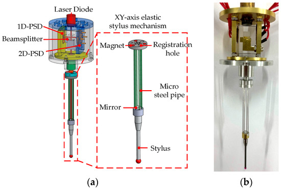
Figure 1.
Structure and schematic view of the XY-axis modular elastic stylus mechanism: (a) structural schematic, (b) photograph of the mechanism.
2.2. Z-Axis Mechanism
The Z-axis mechanism is composed of upper and lower bases linked through four flexible leaf springs, as illustrated in Figure 2. This configuration restricts movement in other axes. When a downward force F is exerted along the Z-axis, the compliant leaf springs guide the mechanism to move mainly in the Z-direction, thereby reducing measurement errors.
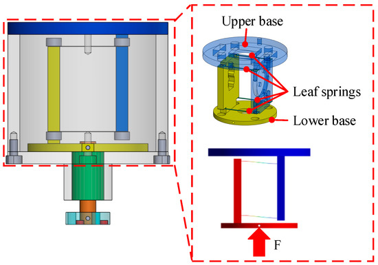
Figure 2.
Illustration of the Z-axis mechanism design and displacement.
3. Finite Element Analysis
A three-dimensional finite element model of the probe was constructed and analyzed in ANSYS. In this analysis, the Solid186 element type, which includes 20 nodes, was applied. The upper and lower bases were modeled using aluminum, the leaf springs were made of SK-2 tool steel, and the microtubes were defined as stainless steel. The corresponding material properties are summarized in Table 1.

Table 1.
Parameters used in ANSYS analysis.
To ensure the probe meets both design and measurement requirements—including deformation rate and yield stress of the pivot spring—the analysis defined a ±1 mm measuring range for the X-, Y-, and Z-axes. A force corresponding to a 1 mm displacement of the probe tip was applied in each axis direction. The resulting data were extracted to verify whether the design criteria were satisfied. Simulation results are shown in Figure 3, Figure 4 and Figure 5, with data summarized in Table 2. The table shows that the maximum stresses on the leaf springs and steel tubes are lower than the material yield strengths, thus avoiding plastic deformation under normal use. Additionally, the pivot spring’s deformation rate is lower than that of typical commercial 3D scanning probes, which reduces deformation of the measured workpiece during contact.
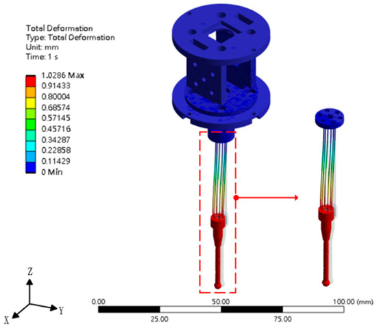
Figure 3.
Analysis of the X-axis’s displacement.
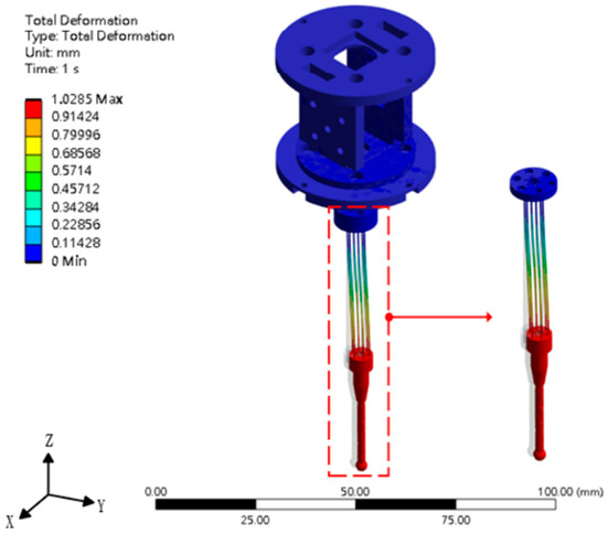
Figure 4.
Analysis of the Y-axis’s displacement.
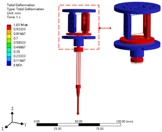
Figure 5.
Analysis of the Z-axis’s displacement.
Table 2.
Simulation results of force, displacement, and stress obtained from ANSYS.
As illustrated in Figure 6, the stylus mechanism can be modeled by analyzing the forces acting on the probe tip. Based on the symmetric structure, the resulting motion can be described under different angular conditions of φ = 90° and θ = 0–90°. Finite-element analysis (FEA) was performed to investigate how a 0.24 N contact force affected the translational and rotational motions of the stylus suspension and probe tip. The corresponding results are presented in Figure 7 and Table 3.
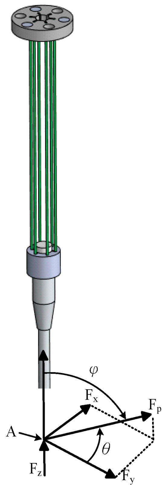
Figure 6.
Free-body diagram of the stylus mechanism.
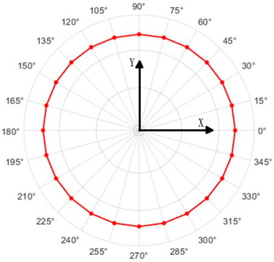
Figure 7.
Axial angle of the probe.
Table 3.
Simulation results of displacement and error obtained from ANSYS (φ = 90°, θ = 0~90°).
4. Measuring System
Given that the structure analyzed in this study possesses only three degrees of freedom, two sensors were employed to capture the variations across these three degrees. The measurement system is illustrated in Figure 8. In the optical design, a laser diode serves as the light source. The emitted light beam is split into two by a beam splitter. One beam is directed onto 1D-PSD. As the 1D PSD is fixed to the lower base, any displacement along the Z-axis produces a voltage variation, which allows detection of Z-axis movement. The other beam is reflected by the probe’s reflector and directed to 2D-PSD. 2D PSD detects changes in the probe’s angular displacement. Both PSDs generate voltage signals when light hits their active sensing areas, allowing determination of the spot position, as shown in Figure 8. For 1D PSD, ends A and B produce voltage signals V1 and V2, respectively, as shown in the equation:
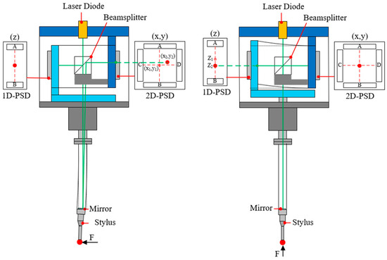
Figure 8.
Design and configuration optical path.
When the conversion relationship is applied, the PSD’s center is taken as the reference origin. As the incident beam shifts, a nonlinear voltage response is generated, from which the beam position can be calculated. Consequently, the displacement along the Z-direction is obtained. Similarly, when the light beam reaches 2D PSD, terminals A, B, C, and D produce corresponding voltage outputs V1, V2, V3, and V4, as given in the following expression:
5. Results
After validating the finite element analysis and verifying that the sensor configuration met the design requirements using ANSYS 2024 R1 software, the key experimental objective was to evaluate the repeatability, which is crucial for precision in probe measurements. The experiment assessed measurement uncertainty, where a lower value indicates higher accuracy. The experimental setup is illustrated in Figure 9. A linear motor, acting as the drive shaft, was used to move the stylus tip horizontally. The displacement of the ball at the tip was measured using a Doppler laser interferometer (Model MCV-500), which provides a resolution of 0.1 nm and is equipped with pressure and temperature compensation to minimize measurement errors. As illustrated in Figure 9, the voltage output was conditioned using an amplifier followed by a signal processing circuit, then digitized using the PCI-6013 data acquisition interface from National Instruments. The data were read and recorded by a computer, which acted as the central unit for the entire measurement system. Initially, the linear motor platform was positioned appropriately, then advanced 10 µm to observe the simultaneous output signals of the probe’s X, Y, and Z axes. When the platform reached the designated position, it triggered the A/D conversion and repeated the measurement. The displacements recorded through this process are listed in Table 4. The results indicate that the probe achieved a unidirectional repeatability of 0.18 µm. Sources of measurement error were the plastic deformation of the leaf spring, the motor’s movement speed, and environmental factors such as temperature and vibration.
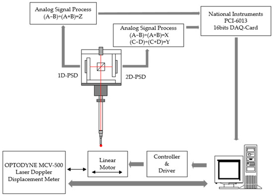
Figure 9.
Experimental setup for testing the measurement capability of the scanning probe.
Table 4.
Unidirectional repeatability.
6. Conclusions
The purpose of this study was to develop a 3D scanning probe with high precision and low contact force. The probe mechanism consisted of a Z-axis module and an XY-axis module, with its degrees of freedom constrained to three. The design was validated using the finite-element software ANSYS, where static analyses were performed to assess the displacements along the Z-axis and the XY-axes, as well as the deformation and maximum stress of the leaf springs to ensure compliance with design requirements. The sensing system utilized a laser diode and position-sensitive detectors (PSDs). Through a well-designed optical path, the system was able to measure angular displacements along the Z and XY axes. The complete measurement system achieved a measurement range of ±1 × ±1 × 1 mm and a unidirectional repeatability of 0.18 μm.
Author Contributions
Conceptualization, C.-L.C.; methodology, C.-L.C.; software, C.-Y.Y.; validation, C.-L.C. and C.-Y.Y.; formal analysis, C.-L.C.; investigation, C.-L.C. and C.-Y.Y.; resources, C.-L.C.; data curation, C.-L.C. and C.-Y.Y.; writing—original draft preparation, C.-L.C. and C.-Y.Y.; writing—review and editing, C.-L.C.; visualization, C.-L.C. and C.-Y.Y.; supervision, C.-L.C.; project administration, C.-L.C.; funding acquisition, C.-L.C. All authors have read and agreed to the published version of the manuscript.
Funding
This research was financially supported by the National Science and Technology Council, Taiwan. (Project No. NSTC 113-2637-E-218-003), for which the authors express their sincere gratitude.
Institutional Review Board Statement
Not applicable.
Informed Consent Statement
Not applicable.
Data Availability Statement
The raw data supporting the conclusions of this article will be made available by the authors on request.
Conflicts of Interest
The authors declare no conflict of interest.
References
- Peggs, G.N.; Lewis, A.J.; Oldfield, S. Design for a Compact High-Accuracy CMM. CIRP Ann. 1999, 48, 417–420. [Google Scholar] [CrossRef]
- Chu, C.-L.; Chiu, C.-Y. Development of a Low-Cost Nanoscale Touch Trigger Probe Based on Two Commercial DVD Pick-up Heads. Meas. Sci. Technol. 2007, 18, 1831–1842. [Google Scholar] [CrossRef]
- Küng, A.; Meli, F.; Thalmann, R. Ultraprecision Micro-CMM Using a Low Force 3D Touch Probe. Meas. Sci. Technol. 2007, 18, 319–327. [Google Scholar] [CrossRef]
- Liebrich, T.; Knapp, W. New Concept of a 3D-Probing System for Micro-Components. CIRP Ann. 2010, 59, 513–516. [Google Scholar] [CrossRef]
- Li, R.-J.; Fan, K.-C.; Huang, Q.-X.; Zhou, H.; Gong, E.-M.; Xiang, M. A Long-Stroke 3D Contact Scanning Probe for Micro/Nano Coordinate Measuring Machine. Precis. Eng. 2016, 43, 220–229. [Google Scholar] [CrossRef]
- Haitjema, H.; Pril, W.O.; Schellekens, P.H.J. Development of a Silicon-Based Nanoprobe System for 3-D Measurements. CIRP Ann. 2001, 50, 365–368. [Google Scholar] [CrossRef]
- Kim, S.-W.; Yang, D.Y. New Design of Precision CMM Based upon Volumetric Phase-Measuring Interferometry. CIRP Ann. 2001, 50, 357–360. [Google Scholar] [CrossRef]
- Fan, K.-C.; Cheng, F.; Wang, W.; Chen, Y.; Lin, J.-Y. A Scanning Contact Probe for a Micro-Coordinate Measuring Machine (CMM). Meas. Sci. Technol. 2010, 21, 054002. [Google Scholar] [CrossRef]


Disclaimer/Publisher’s Note: The statements, opinions and data contained in all publications are solely those of the individual author(s) and contributor(s) and not of MDPI and/or the editor(s). MDPI and/or the editor(s) disclaim responsibility for any injury to people or property resulting from any ideas, methods, instructions or products referred to in the content. |
© 2025 by the authors. Licensee MDPI, Basel, Switzerland. This article is an open access article distributed under the terms and conditions of the Creative Commons Attribution (CC BY) license (https://creativecommons.org/licenses/by/4.0/).