Abstract
Aluminum, one of the most abundant metals found on our planet, plays a crucial role in manufacturing as it is lightweight and resistant to corrosion and has excellent machinability. Of its numerous alloys, Al6061 is one of the most popular alloys used for CNC machining due to its superior mechanical and processing properties. This paper aims to investigate the impact of machining under dry and wet machining conditions. Correspondingly, the impact of dry machining on the material removal rate (MRR) and surface roughness (Ra) of Al6061 was evaluated. Machining was performed on a CNC Lathe. Two rods of Al6061 were used, and a dynamometer was attached to them to measure the radial, thrust, and tangential forces. In wet machining, the coolant used was a mixture of cutting oil and water. Different RPMs, feed rates, and depths of cut were entered into the machine as parameters. And the optimum parameters where found. This research utilizes particle swarm optimization approaches in order to evaluate optimal parameters, in contrast to traditional measurement methods such as contact profilometry or cutting force measurement. The results indicate that surface roughness rises with the depth of cut and feed rate. Ra rises by about 200% when dry machining is conducted at 0.05 mm/rev with increased depths of cut from 0.5 mm to 2.5 mm. In wet machining, the rise is much smaller, approximately 67% at 0.05 mm/rev and 30% at 0.25 mm/rev. Wet machining always produces more finished surfaces, decreasing Ra by 22–25% over dry machining. Wet machining is therefore better suited for achieving high-quality surface finish in Al6061 machining.
1. Introduction
There are various types of metals and non-metals used in different industries. The various types of metals used are iron, steel, copper, brass, titanium lead, aluminum, and more. Different metals have unique properties and are selected according to their application. However, aluminum is widely used due to its excellent mechanical properties, corrosion resistance, good machinability, and recyclability. It is particularly important in applications such as automotive, aerospace, and structural components. By machining this material, we can achieve the high quality of holes, which increases the product quality, surface roughness (Ra), and material removal rate (MRR). Ra is crucial because it determines both the product’s quality and its esthetic appeal. In traditional machining processes, coolant is used to reduce the heat generated, which increases efficiency and reduces tool wear. However, the cost of coolant has increased, and coolant is harmful to both humans and the environment. To make machining processes sustainable, dry machining has been used more in industry. It is eco-friendly and also cost-saving. We will study the effect of dry machining on the Ra and MRR of Al6061, compared to machining with lubricants. This comparison will help evaluate whether dry machining can achieve similar or better performance in terms of surface quality and productivity. Recently, there has been a rise in nature-inspired optimization techniques, such as swarm optimization, which significantly boosts machining efficiency. These approaches are great for picking the best cutting parameters, which in turn improves Ra and the MRR. In this study, we dive into particle swarm optimization (PSO) to find the ideal machining conditions for the Al6061 alloy.
2. Literature Review
In this study, we consider machining parameters, Ra, MRR, and the tool materials typically used in the dry machining and wet machining of Al6061, with references to previous studies. In machining processes, the choice of parameters like cutting speed, feed rate, depth of cut, tool material, and tool geometry is of prime importance in controlling surface roughness and the material removal rate (MRR), especially when making a comparison between dry and wet machining. Lower cutting speeds ranging from 60 to 120 m/min are used in dry machining conditions where heat generation must be controlled due to the lack of coolants. Conversely, wet machining permits faster cutting speeds, normally as high as 180 m/min or greater, due to successful heat dissipation by coolants. One study concluded that dry machining tends to produce higher surface roughness values (Ra, Rz, Rq) and a lower MRR, whereas wet machining enhances surface finish as well as productivity [1,2].
Feed rate is also a determining factor. Feed rates in dry machining are generally in the range of 0.05 to 0.3 mm/rev, and a rise in feed rate tends to produce a rougher surface. Wet machining, however, can better handle larger feed rates (0.1 to 0.3 mm/rev) due to enhanced lubrication and cooling, which preserve surface integrity [3,4,5]. Studies proved that even though higher feed rates could increase the MRR, they could also worsen the surface finish if not well regulated. The depth of cut also affects roughness and productivity in the same manner. Dry machining tends to use smaller cuts (0.5 to 2 mm) to avoid the buildup of heat, while wet machining can use higher cuts (1 to 4 mm) since coolant is available [3,4,5]. In [6], the authors note that a larger depth of cut in wet machining increases the MRR, but if it is too large, it can have a negative impact on the surface finish. Material selection for the tool has a strong influence on the machining results. Dry machining utilizes heat-resistant materials such as carbide, ceramic, or cermet tools, although these become worn out quicker because of increased friction. Wet machining utilizes materials such as HSS, carbide, or coated carbide with the advantage of lower friction and better life for tools. In [7,8], it was established that dry machining resulted in increased tool wear and surface roughness, while the use of coolants in wet machining improved tool life and produced higher surface quality. Finally, the geometry of the tool, such as parameters like rake angle and edge sharpness, plays a significant role, particularly in dry machining where there is greater friction. High rake angle and sharp edge tools reduce heat and increase the surface finish in dry machining. At the same time, geometries optimized for coolant-controlled cutting in wet machining provide greater surface quality and MRR [7,8]. Tool wear and geometry influence surface roughness to a greater extent in dry machining, as demonstrated by [9], whereas wet machining provides more tolerance in terms of cooling and lubrication [9]. Pavement roughness (IRI) in Laos was predicted using the Adaptive Neuro-Fuzzy Inference System (ANFIS) [10]. Fourteen years of data was used to create two models for DBST and AC roads. Compared to conventional regression techniques, ANFIS demonstrated superior prediction accuracy, focusing on using Response Surface Methodology (RSM) and particle swarm optimization (PSO) to optimize face milling parameters for AA6061 [11,12]. PSO seeks to reduce power consumption, cutting force, and surface roughness. The findings demonstrate that PSO performs more accurately and efficiently than conventional desirability techniques. The authors of [13,14,15,16,17,18] predicted the MRR and SR in the wire-cut EDM of Al7075 with 9% activated carbon by comparing GRNN, SVR, and RVM models. The authors of [7,8] reviewed recent developments in cutting tool life modeling and monitoring with an emphasis on increasing manufacturing cost-effectiveness and efficiency. They examined different wear mechanisms as well as conventional and contemporary tool life models [15,16]. Future directions for tool performance prediction are highlighted in this study, including adaptive self-learning systems and hybrid modeling approaches. Dry machining generally results in higher Ra values (Ra, Rz, Rq) due to increased friction, heat, and tool wear. Lower CSs (cutting speeds), IPM (feed rates), and DOCs (depths of cuts) are often used to mitigate these issues. Wet machining significantly improves surface finish and tool life due to the cooling and lubrication effects of the coolant. Higher cutting speeds, feed rates, and depths of cut are achievable without compromising surface quality, resulting in a higher MRR.
3. Methodology
In terms of the mechanical properties of Al6061, it is a lightweight yet strong aluminum alloy with a density of 2.7 g/cm3. It has a tensile strength of 310 MPa and yield strength of 276 MPa, making it suitable for structural applications. The alloy exhibits a Brinell hardness of 95 HB, ensuring wear resistance. It has a modulus of elasticity of 68.9 GPa, providing good stiffness and resistance to deformation. With an elongation of 12%, it maintains a balance between strength and ductility. Its thermal conductivity of 167 W/m·K allows for efficient heat dissipation, making it ideal for heat-sensitive applications. The chemical composition of Al6061 includes aluminum (95.8–98.6%), along with magnesium (0.8–1.2%) and silicon (0.4–0.8%), which improve strength and corrosion resistance. Copper (0.15–0.4%) enhances hardness, while chromium (0.04–0.35%) improves wear resistance. Small amounts of iron, zinc, manganese, and titanium refine the grain structure and enhance machinability. The alloy is heat-treatable, allowing for further strengthening through the T6 tempering process. The Taguchi Orthogonal Array (OA) method is a design of experiments (DOE) technique used for improving processes by minimizing the number of experiments while ensuring reliable results. It was developed by Dr. Genichi Taguchi and is widely applied in manufacturing, machining, and engineering optimization. The authors of studied PSO as a population-based metaheuristic technique motivated by the collective social behavior of birds flocking or fish schooling. PSO has found extensive use in solving continuous optimization problems based on its ease, efficiency, and speed. Each particle in PSO is a potential solution in the search space that shifts according to its own best experience and the swarm’s best-known position. There are some limitations of the current research on the use of PSO in the machining of Al 6061. Most studies have been performed on the base alloy, and there are fewer on the composites that act differently during machining. Adaptive, real-time optimization is hardly covered, and these studies are mostly conducted offline. The goal of multi-objective optimization can be reduced to a single metric instead of investigating compromises between other factors such as surface finish, tool wear, and energy consumption. Unorthodox and hybrid processes (such as ultrasonic-assisted, cryogenic, EDM, and laser-assisted processes) are also still underdeveloped as well. Additionally, there are few comparative studies of PSO against other algorithms in fair terms; experimentation tends to have weak and small-scale validation. These gaps include those in composite machining, real-time applications, true multi-objective approaches, unconventional machining, more rigorous benchmarks, and more rigorous experiments. Overall, mathematical formulas based on inertia, cognition, and social factors are used to alliteratively update each particle’s position and velocity. In order to decrease Ra and increase the MRR in the machining of Al6061, PSO is used in this study to optimize CNC turning parameters, such as cutting speed, feed rate, and depth of cut. The algorithm searches for the ideal parameter combination that offers the best balance between quality and productivity. The PSO parameters used in this study were selected based on literature standards and improved through testing to produce reliable results.
Figure 1 dry machining was performed on a 30 mm diameter and 450 mm long bar, and wet machining was performed on a 30 mm diameter and 240 mm long bar. In each case, 25 readings were taken. The input parameters taken into consideration while machining were spindle speed (RPM) with values of 600, 900, 1200, 1500, and 1800; feed rate with values of 0.25, 0.2, 0.15, 0.1, and 0.05 mm/rev; and depth of cut fixed at 2.5, 2, 1.5, 1, and 0.5 mm.
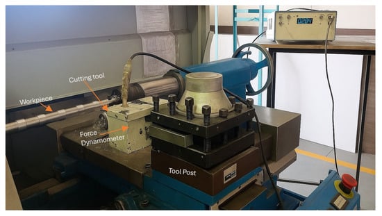
Figure 1.
CNC machining set up.
The output parameters that were quantified included the arithmetic average Ra and MRR. Increasing the RPM (increasing the spindle speed), feed rate (IPM), and depth of cut (DOC) was found to result in an increased MRR. At the same time, however, it caused higher heat generation, faster tool wear, and increased machining instability. It was thus important to balance these parameters to ensure optimum productivity without jeopardizing machining quality.
In wet machining, a coolant composed of a mixture of water and cutting oil was employed. The coolant minimizes cutting temperature and enhances the surface finish. In both dry and wet machining, a digital tool dynamometer was used to record the cutting forces. Three kinds of cutting forces were recorded by the dynamometer: thrust, feed, and radial. These forces showed varying (positive and negative) values with variations in RPM, IPM, and DOC. Chip thickness was found to change with DOC. As the DOC decreased, the chips thinned, and the radial forces decreased.
In dry machining, Ra increases the DOC for different feed rates, as shown in Figure 2. In dry machining at higher IPM, the roughness increases more sharply, and the surface finish tends to worsen as both feed and depth increase.
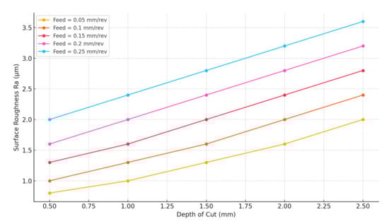
Figure 2.
Ra vs. DOC at various speed rates (dry machining).
In the wet machining graph, lines (solid) are consistently lower than dry machining lines (dashed), as shown in Figure 3. This indicates better surface finish under wet conditions due to reduced depth of cut. The graph shows a general comparison between dry machining and wet machining.
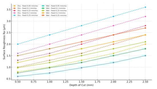
Figure 3.
Ra vs. DOC at various speed rates (wet machining).
The minimum resultant force in dry machining (13.58 N) was achieved at 600 RPM, 0.05 mm/rev feed, and a 0.5 mm depth of cut due to the alignment of minimal mechanical and thermal loads. The minimum spindle speed limits heat generation, whereas the minimum feed rate and low depth of cut reduce the tool’s engagement with the material, thus leading to cutting resistance. These conditions produce finer chips and minimize interface friction. Even in the absence of a coolant, the conservative parameters ensure tool stability and minimize wear, as shown in Table 1. This equilibrium results in very small cutting forces. PSO efficiently determined this set as optimal by assessing trade-offs between force, tool life, and machining stability.

Table 1.
Parameters of dry machining.
The optimal reading for wet machining with the lowest resultant force of 11.57 N was obtained at 600 RPM, 0.05 mm/rev feed, and a 0.5 mm depth of cut based on several factors. Low spindle speed minimizes the generation of heat, and a low depth of cut with slight feed maintains lower material engagement and cutting resistance. The coolant is an important element that reduces friction and efficiently distributes the available heat generated, leading to easier cutting and improved evacuation of chips. These conditions produce even, thin chips and prevent tool overload, as shown in Table 2. In conclusion, the PSO algorithm effectively selected this set of parameters as optimal by analyzing the influence of the machining parameters and coolant on reducing force while ensuring machining stability.
Table 2.
Parameters of wet machining.
4. Results and Discussion
4.1. Dry Machining
The above graph (Figure 4) shows the thrust force as a function of spindle speed (RPM) for each of the five experiments. The blue line shows the steady incremental increase in spindle speed between 600 RPM and 1800 RPM max, as was performed for each of the five trials. The thrust force is shown as a decreasing orange curve from a small positive value to about −100 at the end of the final trial. This implies that spindle speed and thrust force are inversely related, i.e., a lower thrust force is experienced when higher spindle speeds are used in machining.
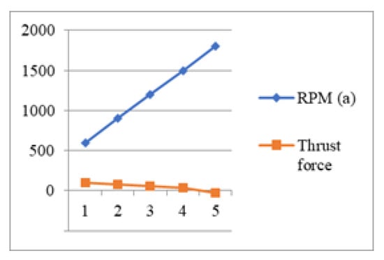
Figure 4.
RPM vs. thrust force.
The above graph (Figure 5) shows the RPM and feed force in the five trials. So, in this case, the spindle speed starts at around 600 RPM and goes to about 1800 RPM in the first five trials, as denoted by the blue graph. In contrast, the feed force (orange) is very different. The RPM (in blue) is nearly stationary (with small positive and negative fluctuations around the center value near zero) with respect to the orange curve. This indicates that in all trials, feed force does not change much even though spindle speed increases a lot, suggesting that the overall feed force is insensitive to spindle speed within the experimental framework.
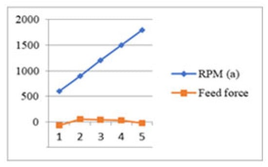
Figure 5.
RPM vs. feed force (dry machining).
Figure 6 illustrates force components (Fx, Fy, Fz) against machining time (seconds). The forces increase first, reach a peak at 20–25 s, and symmetrically decrease afterward, creating a parabolic pattern. Three force components are graphed: Fy (highest peak ~16 N), Fz (middle ~9 N), and Fx (negative, ~–5 N). Both experiment and calculated forces are graphed, with a tight overlap, which reflects a good model fit. The machining operation takes approximately 45 s, and all forces come close to returning to zero at the end.
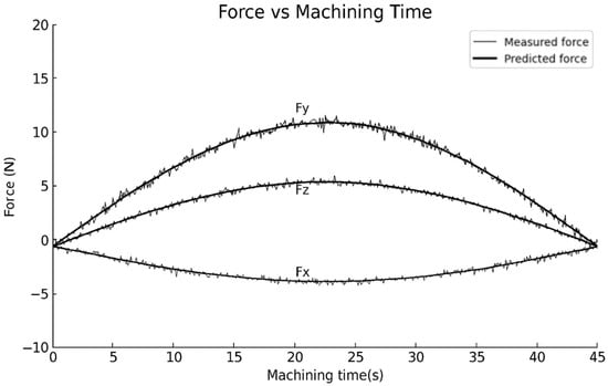
Figure 6.
Force vs. machining time (dry machining).
Figure 7 displays the various force components in the machining process. The Y-axis indicates the force in Newtons, while the X-axis shows the type of force: thrust, feed, or radial. The feed force is the highest at 11.5 N, followed by the thrust force at 6.0 N. The radial force is the lowest at 3.3 N. This comparison helps in assessing tool performance and improving machining parameters.
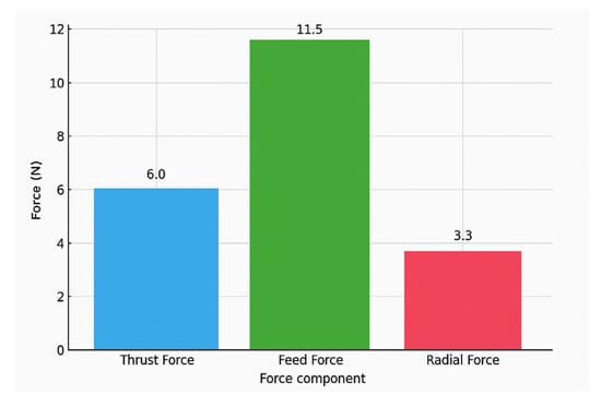
Figure 7.
Force vs. force component (dry machining).
4.2. Wet Machining
Figure 8 presents the variation in RPM and thrust force under five different test conditions. The blue diamond line is for RPM, which rises continuously from about 600 to 1800. The red line with squares represents thrust force, which reduces slowly over the same conditions. Though RPM remains in a linear ascending trend, thrust force demonstrates a minor declining trend. This implies that with an increase in RPM, the thrust force reduces, indicating an inverse proportion.
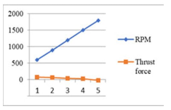
Figure 8.
RPM vs. thrust force (wet machining).
Figure 9 compares RPM and feed force under five test conditions. The blue diamond line indicates that RPM rises linearly from roughly 600 up to 1800. The square orange line represents the feed force, which increases first, reaches its peak at point 3, and decreases afterwards. RPM and feed force show opposite trends after point 3, which may reflect the effect of RPM on reducing feed force. Generally, as RPM increases, feed force increases slightly at first, then decreases, indicating a nonlinear relationship.
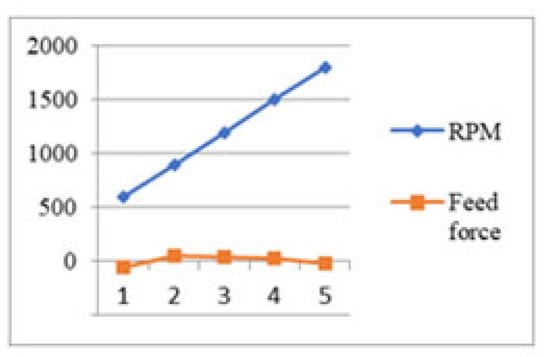
Figure 9.
RPM vs. feed force (wet machining).
Figure 10 shows the change in RPM and radial force in five test conditions. The blue diamond line shows a linear, constant rise in RPM from approximately 600 to 1800. The orange line with squares is representative of radial force, varying a little but staying close to zero. Unlike RPM, radial force shows no clear increasing or decreasing trend, indicating stability. In general, as the RPM rises considerably, the radial force is almost constant with little variation.
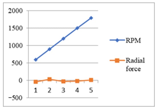
Figure 10.
RPM vs. radial force (wet machining).
Figure 11 illustrates the dynamic behavior of cutting forces (Fx, Fy, Fz) versus machining time, with a comparison between calculated and measured values. Fy (the maximum force) rises slightly until about 15 s and then slowly returns, reaching a peak close to 12 N. Fz is almost unchanged at 5 N with little variation during machining. Fx, the minimum force, varies slightly around −5 N, being relatively stable over time. The narrow overlap of measured and calculated force lines reflects high prediction precision by the model.
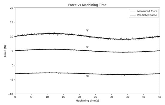
Figure 11.
Force vs. machining time (wet machining).
Figure 12 shows the magnitudes of three machining force components: thrust, feed, and radial forces. Feed force is the largest, with a value of 10 N. Thrust force has a medium value of approximately 5 N, whereas radial force is the smallest with a value of approximately 3 N. It is very clear from the graph that feed force overwhelms the distribution of forces in machining.
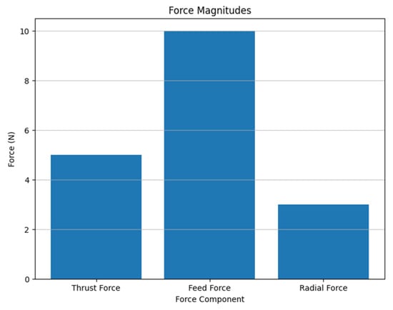
Figure 12.
Force vs. force component (wet machining).
The total resultant force (RF) may be determined from the following formula:
This adds all three force terms into one magnitude.
Dry Machining: Ra rises with the DOC and IPM. At a 0.05 mm/rev feed rate, Ra rises by ~200% when the DOC increases from 0.5 mm to 2.5 mm. This effect is more pronounced at higher IPM. Wet Machining: The same trend is seen but with lower Ra values. At 0.05 mm/rev, Ra rises by ~67%, and at 0.25 mm/rev, it increases by ~30% for the same depth range. Comparison: Wet machining always yields improved surface finish, with a 22–25% decrease in Ra over dry machining under the same conditions.
The experimental findings based on turning show that spindle speed plays a major role in cutting forces. The thrust force and the feed force both diminish with a rise in RPM since the faster movement of the workpiece better enhances efficiency, and there are fewer changes in chip thickness in each revolution, which consequently reduces the force in the cutting and feed route. Radial force is low and varies around zero, which indicates good tool stability and the minimum lateral deflection. Regarding the machining time, forces are greater when the tool enters the workpiece, are at the highest during the mid-cut, and are symmetrically smaller as the operation of the tool reaches the end, in simple terms, forming a parabola pattern. The components of force, feed force, thrust force, and the lowest radial force show that the majority of the cutting power is used in moving the tool into the material, and this also implies that the lateral instabilities are at lower levels, which is a positive indication for dimensional accuracy and surface finish. Based on cutting force distribution with spindle speed, thrust force (Fz) depicts a downward trend with a rise in RPM due to effective chip ejection and minimal spindle contact between the tool and workpiece as a result of adding lubrication. Feed force (Fy) goes up a bit in the mid-RPM range and then levels off or decreases, indicating that feeding force is more smoothly assisted through lubrication. Radial force (Fx) is the lowest with little change, which is evidence that it has great radial stability and few vibrations. This behavior is further confirmed by examining cutting forces versus machining time when there is agreement in the predicted and measured forces. The force is the highest with feed force (~1012 N), intermediate with thrust force (6–7 N), and the smallest with radial force (−5 to −4 N) and shows uniform cutting performance with the minimum deflection of tools. Bar chart data support this trend: feed force (~10 N) is much higher than thrust (~5 N), then radial (~3 N), and this is to be expected when turning, as the chip flow directly opposes feed force. On the whole, wet machining involves cool and lubricating features, which lower the temperature on the tool–chip interface and lead to friction and the possible occurrence of a built-up edge (BUE), particularly in aluminum alloys such as Al6061. The fact that the thrust force decreased as the spindle speed was increased demonstrates the enhanced cutting performance, whereas the generated force profiles remained at the same level, which confirms that the tool wear was minimized. The overriding feed force justifies the necessity to adjust the tool geometry and feed rate to yet again increase the cutting efficiency when turning wet surfaces.
5. Conclusions
Based on this study, it can be concluded that both the feed rate (IPM) and the depth of cut (DOC) have a significant effect on the Ra of Al6061 in dry and wet machining. A greater DOC causes a higher Ra in both processes. Nevertheless, the rise in percentage Ra with an increase in the DOC is comparatively lower in wet machining. Wet machining consistently yields a superior surface finish compared to dry machining, with an improvement of 22–25% in Ra. The influence of the DOC on Ra becomes more pronounced at lower IPM in dry and wet machining.
6. Research Gaps and Opportunities
There is a lack of research on Al6061 machining with PSO in terms of addressing composites, real-time optimization, multi-objective methods, and unconventional processes. Limited comparative studies have been performed with other algorithms and experimental proof. Filling these gaps can further improve the efficacy of PSO and diversify its usage in advanced and smart machining systems.
Author Contributions
Conceptualization, M.U.G. and A.A.S.; methodology, A.M.S. and A.V.L.; software, A.A.S. and A.V.L.; validation, M.G. and A.A.S.; writing—original draft preparation, A.A.S. and M.G.; writing—review and editing, M.U.G., and A.A.S.; visualization, M.U.G.; supervision, A.A.S. and H.M. All authors have read and agreed to the published version of the manuscript.
Funding
This research received no external funding.
Institutional Review Board Statement
Not applicable.
Informed Consent Statement
Not applicable.
Data Availability Statement
New data is not present in this paper.
Conflicts of Interest
The authors declare no conflicts of interest.
References
- Chinchanikar, S.; Choudhury, S.K. Comparative evaluations of nose wear progression and failure modes during hard turning under dry and near-dry cutting conditions. Int. J. Mach. Mach. Mater. 2016, 18, 466–482. [Google Scholar] [CrossRef]
- Somatkar, A.; Dwivedi, R.; Chinchanikar, S. Comparative evaluation of roller burnishing of Al6061-T6 alloy under dry and nanofluid minimum quantity lubrication conditions. Obrab. Met./Met. Work. Mater. Sci. 2024, 26, 57–74. [Google Scholar] [CrossRef]
- Gaikwad, M.U.; Krishnamoorthy, A.; Jatti, V.S. Investigation on effect of process parameter on surface integrity during electrical discharge machining of NiTi 60. Multidiscip. Model. Mater. Struct. 2020, 16, 1385–1394. [Google Scholar] [CrossRef]
- Gupta, M.K.; Sood, P.K. Surface roughness measurements in NFMQL assisted turning of titanium alloys: An optimization approach. Friction 2017, 5, 155–170. [Google Scholar] [CrossRef]
- Somatkar, A.A.; Dwivedi, R.; Chinchanikar, S.S. Enhancing surface integrity and quality through roller burnishing: A comprehensive review of parameters optimization, and applications. Commun. Appl. Nonlinear Anal. 2024, 31, 151–169. [Google Scholar] [CrossRef]
- Dwivedi, R.; Somatkar, A.; Chinchanikar, S. Modeling and optimization of roller burnishing of Al6061-T6 process for minimum surface roughness, better micro hardness and roundness. Met. Work. Mater. Sci. 2024, 26, 52–65. [Google Scholar] [CrossRef]
- Songmene, V.; Khettabi, R.; Zaghbani, I.; Kouam, J.; Djebara, A. Machining and machinability of aluminum alloys. Alum. Alloys Theory Appl. 2011, 377, 400. [Google Scholar]
- Gaikwad, M.U.; A, K.; Jatti, V.S. Estimation of surface integrity parameters in electrical discharge machining (EDM) process-a review. In Proceedings of the 2nd International Conference on Advanced Technologies for Societal Applications, Pandharpur, India, 14–15 December 2018; pp. 601–614. [Google Scholar]
- Khadka, S.; Rahman Rashid, R.A.; Stephens, G.; Papageorgiou, A.; Navarro-Devia, J.; Hägglund, S.; Palanisamy, S. Predicting cutting tool life: Models, modelling, and monitoring. Int. J. Adv. Manuf. Technol. 2025, 136, 3037–3076. [Google Scholar] [CrossRef]
- Yeganefar, A.; Niknam, S.A.; Asadi, R. The use of support vector machine, neural network, and regression analysis to predict and optimize surface roughness and cutting forces in milling. Int. J. Adv. Manuf. Technol. 2019, 105, 951–965. [Google Scholar] [CrossRef]
- Malghan, R.L.; Rao, K.M.; Shettigar, A.K.; Rao, S.S.; D’souza, R.J. Application of particle swarm optimization and response surface methodology for machining parameters optimization of aluminium matrix composites in milling operation. J. Braz. Soc. Mech. Sci. Eng. 2017, 39, 3541–3553. [Google Scholar] [CrossRef]
- Dutta, P.; Majumder, M.; Kumar, A. Parametric optimization of liquid flow process by ANOVA optimized DE, PSO & GA algorithms. Int. J. Eng. Manuf. 2021, 11, 14. [Google Scholar] [CrossRef]
- Gaikwad, M.U.; Gaikwad, P.; Krishnamoorthy, A.; Jatti, V.S.; Ambhore, N.; Oza, A.D.; Kumar, M.; Gupta, M.; Joshi, U. Fatigue analysis of electro discharge machined Nitinol 60. Innov. Emerg. Technol. 2023, 10, 2340009. [Google Scholar] [CrossRef]
- Gaikwad, M.U.; Krishnamoorthy, A.; Jatti, V.S. Implementation of Jaya algorithm for process parameter optimization during EDM processing of NiTi 60 alloy. Mater. Today Proc. 2021, 47, 5701–5708. [Google Scholar] [CrossRef]
- Gaikwad, M.U.; Krishnamoorthy, A.; Jatti, V.S. Investigating the influence of electrical discharge machining process parameter on fatigue strength during machining of titanium grade-2. Mater. Today Proc. 2021, 46, 8951–8957. [Google Scholar] [CrossRef]
- Gaikwad, M.U.; Gaikwad, P.U.; Ambhore, N.; Sharma, A.; Bhosale, S.S. Powder Bed Additive Manufacturing Using Machine Learning Algorithms for Multidisciplinary Applications: A Review and Outlook. Recent Pat. Mech. Eng. 2025, 18, 12–25. [Google Scholar] [CrossRef]
- Singh, N.; Goindi, G. Influence of tool surface texturing on machining performance during turning of aluminium alloy Al6061 under dry conditions. In AIP Conference Proceedings; AIP Publishing LLC.: Melville, NY, USA, 2025; Volume 3218, p. 060005. [Google Scholar]
- Samsuddin, S.; Othman, M.S.; Yusuf, L.M. A review of single and population-based metaheuristic algorithms solving multi depot vehicle routing problem. Int. J. Softw. Eng. Comput. Syst. 2018, 4, 80–93. [Google Scholar] [CrossRef]
Disclaimer/Publisher’s Note: The statements, opinions and data contained in all publications are solely those of the individual author(s) and contributor(s) and not of MDPI and/or the editor(s). MDPI and/or the editor(s) disclaim responsibility for any injury to people or property resulting from any ideas, methods, instructions or products referred to in the content. |
© 2025 by the authors. Licensee MDPI, Basel, Switzerland. This article is an open access article distributed under the terms and conditions of the Creative Commons Attribution (CC BY) license (https://creativecommons.org/licenses/by/4.0/).