Abstract
The difficulty in designing gears to be installed in electric vehicles is caused by the fact that the efficiency of gears is generally treated as a constant value in the entire operating range, while these show significant differences in different operating ranges; therefore, it is necessary to examine the energy and efficiency of the gear, and to create a mathematical model, which can be optimally fitted into the vehicle’s drivetrain in terms of energy. I have performed this modeling in previous years for a single-stage gear unit. However, this model encounters physical limitations, since a larger gear ratio modification cannot be performed in one stage; the number of stages must be increased as the gear ratio increases. As the number of stages increases, the structure of the mathematical model changes, as changes to the gear unit must be incorporated into the model. In this article, an extension of the mathematical model of the gear unit is presented.
1. Introduction
The difficulty in designing drives to be installed in electric vehicles is caused by the fact that the efficiency of the drives is treated as a constant value in the entire operating range, while they show significant differences in different operating ranges; therefore, an energy and efficiency test of the drive is necessary. To carry out this test, it is necessary to create a mathematical model of the drive, with the help of which it can be optimally integrated into the vehicle’s drivetrain in terms of energy [1,2,3].
In the case of drives designed and built in electric vehicles, unlike the drives of vehicles built with conventional internal combustion engines, there is no need for a switchable, gear-changing drive, so a fixed gear ratio must be specified when designing the drivetrain. This ratio and the associated geometric parameters must be specified so that the vehicle operates with minimal energy loss throughout its entire operating range, not only in the gear unit, but also in the entire drivetrain [4,5,6,7].
When implementing a fixed gear ratio, it is important to know how big the gear ratio is, since a small gear ratio can be transmitted in a single-stage gear unit, but in the case of a larger gear ratio, transmission in single-stage gear unit is not possible, because, due to the large gear ratio, the correct tooth contact between the gears cannot be geometrically ensured and therefore, the losses of the gear unit increase. In addition to this, is the disproportionately large size and weight increase in the gear [8,9,10,11,12].
Based on the gear unit construction practice used in the automotive industry, the following applications have been developed:
- Up to 1:6 ratio, one gear is sufficient (imax = 6);
- Two-stage gear units are used for ratios up to 6:36 (imax = 36);
- Three-stage gear units are used for ratios up to 36:216 (imax = 216).
The values listed are not values applied as a scientifically defined rule of thumb but are values of magnitude determined by experience.
2. Presentation of the Concept of the Gear Unit Model
The gear units built into electric cars are usually constant-ratio gears. There are several possible design solutions for their design, such as the following:
- Using externally toothed spur gears;
- Using gears with external–internal teeth contact;
- Using spur gear planetary gear unit.
The modeling procedure was carried out for externally toothed spur gears [13,14,15,16,17,18]. In the first step, a mathematical model of gear units built from conventional gears was created, the physical structure of which is shown in Figure 1.
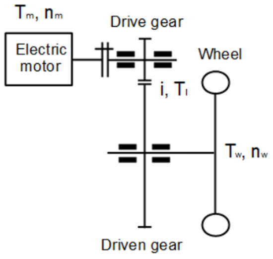
Figure 1.
Physical model of a single-stage external spur gear unit.
The model includes the following:
- The torque (input torque) and speed of the electric motor driving the vehicle;
- The gear units: ideally rigid tooth connection, a flexible shaft and sources of loss;
- The load torque (output torque) results from the vehicle’s traction demand and the rotation of the output shaft.
Drive Unit Parameter Vector Determination
The drive unit model is constructed so that drive unit loss is determined by steady-state examination at work points. This work point examination makes both dynamic and analytical mathematical model application possible during optimization. Parameter determination has key importance in the model’s construction, by which drive unit can be optimized [19]. These parameters are independent variables, which can unambiguously determine a given drive unit [20]. Parameter vectors create a space where drive unit optimization is realized. The drive unit parameter vector is determined as in Equation (1):
where
p[i, m, aw, b, α, β]
- Transmission ratio, [-] → i;
- Module, mm → m;
- Center distance, mm → aw;
- Gear width, mm → b;
- Pressure angle, rad → α;
- Helix angle, rad → β.
3. Extension of the Model to Two-Stage Constant Ratio Gear Units
The first step was to determine the parameter vector of the two-stage gear unit, which can be performed by combining the parameter vectors of the two separate stages in the following way. The first gear stage, which determines the ratio between the motor shaft and the auxiliary shaft, has the following parameter vector and is determined as in Equation (2):
The physical model of a two-stage external spur gear unit is shown in Figure 2.
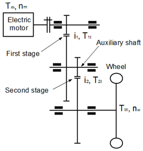
Figure 2.
Physical model of a two-stage external spur gear unit.
The parameter vector of the second stage, which determines the ratio between the auxiliary shaft and the output shaft, is determined as in Equation (3):
The parameter vectors contain the independent design variables that uniquely define a gear unit and since the model will be used for optimization purposes later, in order to simplify the optimization, it is worth organizing the parameter vectors into a vector, which can be given in the following Equations (4) and (5):
The gear unit model determines the losses of the transmission in the form of loss torque (Tl). These loss torques are determined step by step and calculated backwards in the drivetrain, since the operating points characteristic of the vehicle’s operation are available as starting data during the energetic analysis of the transmission. The work points are determined from the vehicle’s given operating point wheel speed and torque (nw, Tw). The first step is to determine the loss torque (T2l) of the second stage, knowing that the drive torque (T2) of the second stage can be calculated using the following Equation (6):
The input torque of the second stage will be the output torque of the first stage, knowing that the loss torque of the first stage (T1l) can be determined and knowing these values, the input torque of the first stage (T1) can be calculated, which is also equal to the load torque (TEm) of the drive electric motor at the given operating point, this can be determined by the following Equation (7):
Knowing the loss torques of the two stages, the total loss torque of the gear at the given operating point can be determined using the following Equation (8):
It is not practical to sum up the losses of the stages in the form of torque, since during the energetic analysis of the gear unit, losses must be determined in the form of power, and since the two different loss torques are associated with two different shaft speeds, it is therefore worth converting the loss torque to loss power (P1l, P2l) for each stage using the following Equations (9) and (10):
- n1: the first gear-stage drive speed;
- n2: the second gear-stage drive speed.
The power losses can now be added using the following Equation (11):
4. Extension of the Model to n-Stage Constant Ratio Gear Units
The loss model of the two-stage gear unit can be extended to n-stage gear units, in such a way that the loss torques are defined for each stage, knowing that the total loss torque of the gear unit at the given operating point can be determined with the following Equation (12):
It is not practical to sum up the losses of the stages in the form of torque, since during the energetic analysis of the gear unit, losses must be determined in the form of power, and since different loss torques are associated with different shaft speeds, it is therefore worthwhile to convert the loss torque to loss power (P1l, …, Pnl) for each stage using the following Equation (13):
The physical model of the n-stage gear units is shown in Figure 3.
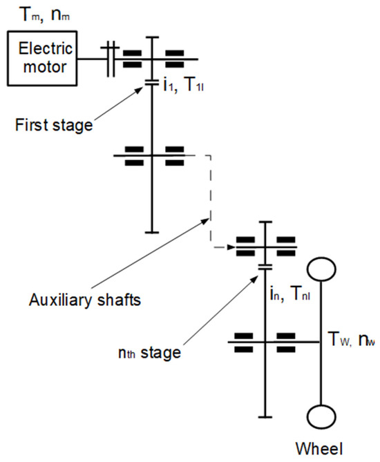
Figure 3.
Extension of the physical model of the gear units from train to n stages.
Then, the relationship between the power losses determined per stage is generalized to gear units with n ratios using the following Equations (14) and (15):
Given the relationships presented in this chapter, the gear unit model can be extended to multi-stage constant-ratio gear units or even planetary gears.
5. Case Study
The parameters of the two-speed model under investigation are given by a Bosch bicycle drive, where the maximum power of the drive is 250 W and the maximum torque is 40 Nm. The drive parameter vector is as shown in Equations (16) and (17):
To determine the efficiency range of the drivetrain, the test range must be defined, which is defined by the operating points describing the operating conditions of a bicycle. A working point is described by the pair of the wheel’s speed and the torque demand from the traction force associated with the working point (nw, Tw), based on which the test was carried out in the range nw = 14… 252 rpm, Tw = 2… 40 Nm.
Figure 4 shows the efficiency field of the tested gear unit.
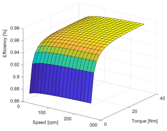
Figure 4.
Efficiency field of the two-stage gear unit under study. (The efficiency of the system improves as it moves from blue to yellow.)
Taking into account the parameters of the two-stage gearbox, a single-stage gearbox has been defined whose gear ratio is equal to the total gear ratio of the two-stage gearbox, which is determined by the following Equation (18):
Knowing this, the parameter vector of the drive is as follows (19):
The result of the run is shown in Figure 5.
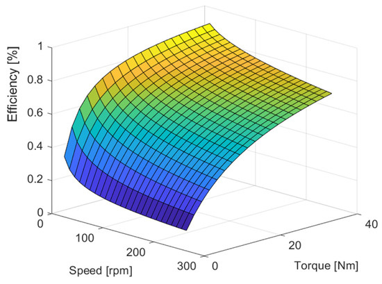
Figure 5.
Efficiency field of the tested single-stage gear unit. (The efficiency of the system improves as it moves from blue to yellow.)
To make the difference between the efficiency ranges of the two gear units easier to interpret, a table (Table 1) has been prepared, which presents the efficiency values at four different boundary points of the operating range.

Table 1.
The efficiency values at four different boundary points of the operating range.
Examining the results obtained at the boundary points, it is clear that the efficiency values of the single-stage gearbox are significantly worse due to the large gear ratio. When examining the efficiency values, it can also be observed that in the case of the results obtained by the single-stage model, the efficiency deterioration is significantly greater at high-speed operating points, which is due to the effect of speed-dependent loss sources [21,22,23].
6. Conclusions
In the case of gear units designed and built in electric vehicles, unlike the gearboxes of vehicles built with traditional internal combustion engines, there is no need for a gear unit that can be switched and can change gears, so a fixed-ratio gear unit must be specified when designing the drivetrain.
In case of lower gear ratios, a single-stage gear unit can be used to achieve torque modification, but in the case of higher gear ratios, multi-stage gear units are needed. In previous years, a model of single-stage gear units was already developed, the extension of which to multi-stage gear units is presented in this article.
When creating the multi-stage gear unit model, the structure of the model, the types and structure of the parameters necessary for testing the gear unit were presented.
With the help of the created model, a comparative study of two gear units was presented through an example, the real basis of which were the parameters of a Bosch two-speed bicycle drive. During the investigation, the overall gear ratio of the gear unit was determined, with which we created a single-stage gear unit. We determined the operating range of the drives, in which we examined the efficiency range of both drives.
By examining the efficiency fields of the gears, it can be concluded that in the case of large ratios, the efficiency of single-stage gears is significantly worse than that of multi-stage ones, which is typically due to friction losses resulting from geometric problems that increase due to the large ratio and increased oil and air turbulence losses.
Funding
The research was supported by the European Union within the framework of the National Laboratory for Autonomous Systems (RRF-2.3.1-21-2022-00002).
Institutional Review Board Statement
Not applicable.
Informed Consent Statement
Not applicable.
Data Availability Statement
The raw data supporting the conclusions of this article will be made available by the authors on request.
Conflicts of Interest
The author declares no conflicts of interest.
References
- Lei, G.; Wang, T.; Zhu, J.; Guo, Y.; Wang, S. System-level design optimization method for electrical drive systems–robust approach. IEEE Trans. Ind. Electron. 2015, 62, 4702–4713. [Google Scholar] [CrossRef]
- Qin, Z.; Wu, Y.T.; Lyu, S.K. A review of recent advances in design optimization of gearbox. Int. J. Precis. Eng. Manuf. 2018, 19, 1753–1762. [Google Scholar] [CrossRef]
- Lakatos, I.; Titrik, Á. Determination of power and torque curves of vehicles based on diagnostic methods. In Proceedings of the 12th International Conference on Heat Engines and Environmental Protection, Budapest, Hungary, 27–29 May 2015; pp. 1–7. [Google Scholar]
- Németh, A.; Fischer, S. Investigation of the glued insulated rail joints applied to CWR tracks. Facta Univ. Ser. Mech. Eng. 2021, 19, 681–704. [Google Scholar] [CrossRef]
- Szalai, S.; Kocsis Szürke, S.; Harangozó, D.; Fischer, S. Investigation of deformations of a lithium-polymer cell using the Digital Image Correlation Method (DICM). Rep. Mech. Eng. 2022, 3, 116–134. [Google Scholar] [CrossRef]
- Horváth, E.; Kőrös, P. Systematic approach to software related tasks in electric fuel-efficiency vehicle development. In Proceedings of the IEEE 19th International Conference on Intelligent Engineering Systems (INES 2015), Bratislava, Slovakia, 3–5 September 2015; pp. 375–378. [Google Scholar]
- Istenes, G.; Pusztai, Z.; Kőrös, P.; Horváth, Z.; Friedler, F. Kriging-assisted multi-objective optimization framework for electric motors using predetermined driving strategy. Energies 2023, 16, 4713. [Google Scholar] [CrossRef]
- Ahssan, M.R.; Ektesabi, M.; Gorji, S. Gear ratio optimization along with a novel gearshift scheduling strategy for a two-speed transmission system in electric vehicle. Energies 2020, 13, 5073. [Google Scholar] [CrossRef]
- Goodarzi, E.; Ziaei, M.; Hosseinipour, E.Z. Introduction to Optimization Analysis in Hydrosystem Engineering; Springer: Berlin/Heidelberg, Germany, 2014; pp. 111–148. [Google Scholar]
- Reitschuster, S.; Illenberger, C.M.; Tobie, T.; Stahl, K. Application of high performance polymer gears in light urban electric vehicle powertrains. Forschung Im Ingenieurwesen 2022, 86, 683–691. [Google Scholar] [CrossRef]
- Prabhakaran, S.; Balaji, D.S.; Joel, C. Stress analysis and effect of misalignment in spur gear. Int. J. Appl. Eng. Res. 2014, 9, 973–4562. [Google Scholar]
- Hoehn, B.R.; Michaelis, K.; Hinterstoiser, M. Optimization of gearbox efficiency. GOMABN 2009, 48, 462–480. [Google Scholar]
- Tudose, L.; Buiga, O.; Jucan, D. Multi-objective optimization in helical gears design. In Proceedings of the Fifth International Symposium about Design in Mechanical Engineering—KOD, Novi Sad, Serbia, 15–16 April 2008; pp. 77–84. [Google Scholar]
- Sanghvi, R.C.; Vashi, A.S.; Patolia, H.P.; Jivani, R.G. Multi-objective optimization of two-stage helical gear train using NSGA-II. J. Optim. 2014, 2014, 670297. [Google Scholar] [CrossRef]
- Patil, M.; Ramkumar, P.; Shankar, K. Multi-objective optimization of the two-stage helical gearbox with tribological constraints. Mech. Mach. Theory 2019, 138, 38–57. [Google Scholar] [CrossRef]
- Bittner, F.; Hahn, I. Kriging-assisted multi-objective particle swarm optimization of permanent magnet synchronous machine for hybrid and electric cars. In Proceedings of the 2013 International Electric Machines & Drives Conference, Chicago, IL, USA, 12–15 May 2013; pp. 15–22. [Google Scholar]
- Bingham, C.; Walsh, C.; Carroll, S. Impact of driving characteristics on electric vehicle energy consumption and range. IET Intell. Transp. Syst. 2012, 6, 29–35. [Google Scholar] [CrossRef]
- Stabile, P.; Ballo, F.; Mastinu, G.; Gobbi, M. An ultra-efficient lightweight electric vehicle—Power demand analysis to enable lightweight construction. Energies 2021, 14, 766. [Google Scholar] [CrossRef]
- Polák, J.; Lakatos, I. Efficiency optimization of electric permanent magnet motor driven vehicle. Mach. Des. 2015, 7, 11–14. [Google Scholar]
- Polák, J.; Lakatos, I. Examination of drive line mathematical model. Mach. Des. 2016, 8, 33–36. [Google Scholar]
- Padilla, G.; Pelosi, C.; Beckers, C.; Donkers, M. Eco-driving for energy efficient cornering of electric vehicles in urban scenarios. IFAC-PapersOnLine 2020, 53, 13816–13821. [Google Scholar] [CrossRef]
- Simon, V.V. Multi-objective optimization of hypoid gears to improve operating characteristics. Mech. Mach. Theory 2020, 146, 103727. [Google Scholar] [CrossRef]
- Eremeev, P.; De Cock, A.; Devriendt, H.; Melckenbeeck, I.; Desmet, W. Single and multi-objective optimization of a gearbox considering dynamic performance and assemblability. Procedia CIRP 2022, 106, 76–83. [Google Scholar] [CrossRef]


Disclaimer/Publisher’s Note: The statements, opinions and data contained in all publications are solely those of the individual author(s) and contributor(s) and not of MDPI and/or the editor(s). MDPI and/or the editor(s) disclaim responsibility for any injury to people or property resulting from any ideas, methods, instructions or products referred to in the content. |
© 2025 by the author. Licensee MDPI, Basel, Switzerland. This article is an open access article distributed under the terms and conditions of the Creative Commons Attribution (CC BY) license (https://creativecommons.org/licenses/by/4.0/).