Abstract
This paper introduces a control-oriented Linear Parameter Varying (LPV) model of an energy-efficient electric vehicle, enhanced to account for wind-induced disturbances. The proposed model structure is designed to support model-based control strategies focused on minimizing energy consumption. In addition to core control inputs—such as torque reference and cornering radius—the model integrates a simulated representation of wind effects on the vehicle’s longitudinal dynamics. To manage the underlying nonlinearities of the vehicle dynamics, a trajectory-based linearization approach was employed to construct the baseline LPV model without wind effects. The accuracy of the extended model was validated using real-world speed profile data. Owing to its modular and control-compatible design, the model provides a solid foundation for testing and developing energy-saving control strategies, making it especially applicable to the design and operation of energy-efficient electric vehicles. The proposed model holds significant potential for further reducing energy consumption, particularly in urban transportation scenarios.
1. Introduction
Vehicle development targeting sustainability is essential, as the transportation sector significantly contributes to global greenhouse gas emissions—accounting for approximately 20% of total global CO2 emissions [1]. The Shell Eco-marathon (SEM) is a prestigious international competition held annually, offering teams from educational institutions the opportunity to showcase innovative, energy-efficient vehicle solutions. During the event, vehicles must complete approximately 16 km within 40 min. The objective is to achieve a valid run in the shortest possible time while consuming the least amount of energy. The investigated vehicle is a Battery Electric Urban Concept vehicle (Figure 1), which achieved first place in the Shell Eco-marathon’s Battery Electric–Urban Concept category in 2024, with a calculated energy consumption of 309 km/kWh. Besides minimizing the losses, following the predetermined driving strategy is key for SEM. The driving strategy is optimized through a measurement-model-based approach using evolutionary algorithms. This process creates an offline strategy, which ensures the least energy consumption on the given track. The only interfering factor in implementing the strategy is the arising external disturbances, such as wind and traffic.
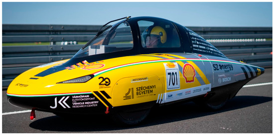
Figure 1.
SZEmission: Battery Electric Urban Concept Vehicle designed for Shell Eco-marathon.
2. Literature Review
The handling and prediction of wind effects are important factors in numerous systems and applications, especially in controlling aerial vehicles (AV), estimating wind velocity can be addressed several ways [2,3,4]. The wind not only affect AV’s but also influence path planning and energy consumption of ground vehicles. Vehicle path prediction accuracy was improved by estimating lateral velocity and external disturbances, including wind effects in [5]. A wind speed prediction method based on the nonlinear Lorenz system is proposed in [6]. Energy-efficient operation of electric vehicles under real-world driving conditions, accurate and control-oriented vehicle models are essential.
The present work introduces a wind-disturbance-integrated Linear Parameter-Varying (LPV) model, specifically designed to support energy-minimizing control strategies. LPV modeling approximates nonlinear dynamics in a linear-like structure by using a time-varying scheduling parameter that captures variations in the nonlinear behavior. This approach allows the model to represent nonlinear vehicle dynamics while retaining the analytical advantages of linear systems. The relevance of this approach is evident in the context of the Shell Eco-marathon, where accurate vehicle modeling is essential to reduce operational energy consumption. At the same time, the LPV formalism entails a low computational burden, which further supports its practical applicability. LPV structures are applicable for modeling a wide range of physical systems and processes, including applications targeting trajectory tracking and control of autonomous vehicles [7,8,9,10]. Extensive research has addressed the development of conversion techniques for reducing nonlinear models into less complex LPV representations [11]. The complete approach is generally avoided because its strong nonlinear dependencies make implementation difficult [12].
Wind disturbances remain a critical factor in civil aviation safety, within this context, LPV-based modeling and robust control frameworks have been proposed [13]. Similarly, in the automotive application, crosswind and road-induced lateral force disturbances have been addressed through an LPV formulation coupled with Moving Horizon Estimation (MHE), enabling effective disturbance estimation under varying speeds [14].
3. Materials and Methods
The linearized model is presented in this section, to provide full overview of the design steps. The experimental energy-efficient electric vehicle is modeled as a nonlinear system, where the powertrain generates the traction force that drives the vehicle. Its longitudinal dynamics can be well approximated by Newton’s second law of motion. A detailed description of the modeling procedure is provided in [8]. Although the measurement-based model is suitable for offline optimization of the driving strategy, it is not practical for real-time control. A general representation of the nonlinear system is given in Equation (1), where represents the system states, the outputs, and the external disturbance.
In the case of the nonlinear model, equilibrium points are defined as those locations in the parameter space where the derivatives of the state variables are zero. In the investigated case the equilibrium points are usually far from the operating points. The introduced shifted variables for states, input and disturbances, respectively, (), represent the deviations from the equilibrium point (), as shown in the following equations:
The system can be described in linearized form with using the state () input () and disturbance () matrices as follows:
In the presented case, a non-equilibrium, trajectory-based linearization approach was applied to model the dynamics of the experimental vehicle, rather than relying on linearization around an equilibrium point. This choice was motivated by the vehicle’s low resistance forces, which resulted in only a narrow portion of the available torque range allowing the formulation of a valid equilibrium equation. Although this method is computationally more expensive, it provides an essential extension for accurately describing the system’s behavior under the given operating conditions.
The general continuous-time state-space representation of LPV systems can be written in the form presented in Equation (4).
The scheduling parameter , is a time-varying system parameter that represents the nonlinear characteristics of the system. LPV modeling provides an effective framework for representing a nonlinear system as linear within a control context. Despite its parameter dependence, this linear structure can be efficiently applied in real-time system modeling. The scheduling parameters were chosen to span the full operating range, as illustrated in Table 1. below across the torque–vehicle speed–cornering radius domain. A more detailed explanation of the linearized model within this operating range is provided in [7].

Table 1.
Range of the scheduling parameters of the LPV system.
The model retains the same state vector and input as the nonlinear formulation (torque and cornering radius); however, for control purposes, the output vector has been augmented with the powertrain efficiency and the actual torque. The actual dimensions of the state (), input (), output () and feedthrough (D) matrices are shown in Equation (5).
4. Results and Discussion
A custom wind measurement unit was employed to record real wind patterns. The device was mounted on a tripod to ensure portability and stable deployment in outdoor conditions. The sensing components were installed on a milled aluminum platform, which included a wind speed sensor (anemometer), a wind direction sensor (anemoscope), and a bubble level to facilitate horizontal alignment on uneven terrain. Signal processing was performed by an onboard microcontroller, which enabled real-time wireless data transmission with a radio communication module. A schematic of the complete measurement setup, along with representative real wind patterns, is shown in Figure 2a.
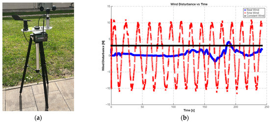
Figure 2.
(a) Custom wind measurement unit. (b) Applied wind patterns as input signals to test the simulation model: red—sine wave pattern with 10 N amplitude and 0.4 rad/s frequency, superimposed with additive Gaussian noise; black—constant headwind; blue—measured wind data from a relatively calm day.
To evaluate the simulation model under varying wind disturbance conditions, multiple input signals were applied (Figure 2b). These included both synthetic signals—such as constant and sinusoidal inputs used to verify the model’s response characteristics—and real wind profiles recorded by the measurement device. This allowed for comprehensive testing of the model’s ability to represent the various environmental effects.
The previously developed LPV model can represent the measurement-based nonlinear vehicle model. However, in its original form, it does not account for wind effects. Wind is a significant factor for this lightweight vehicle, as clearly illustrated by the simulation comparison in Figure 3. The blue curve corresponds to the nonlinear reference simulation, whereas the red curve illustrates the behavior of the LPV model without wind disturbance integration.
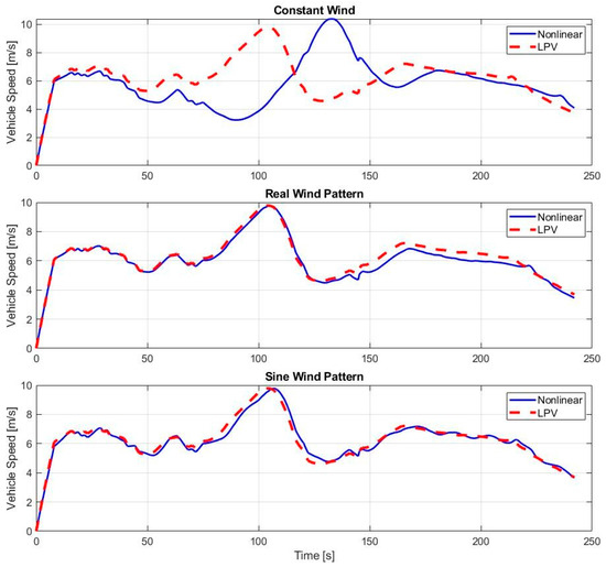
Figure 3.
Simulation of wind effects using multiple wind pattern inputs—without wind extension.
To create a wind disturbance integrated LPV model, the wind effect should be treated as a disturbance input in addition to the control inputs. The set of grid points of the scheduling parameters is denoted by , and its size is defined by Equation (6). Auxiliary matrices are introduced to represent the wind effect on the input, feedthrough, and offset matrices as proposed in Equations (7)–(9).
The augmented matrices are defined as shown in Equations (10)–(12). The presented modification must be applied across the grid points of the scheduling parameters.
After implementing the abovementioned modification, the LPV model can handle the effect of wind, which is handled through disturbance input. The extended model is tested with the same set of wind disturbance pattern as before. The result is shown in Figure 4.
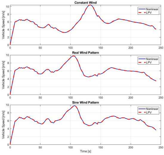
Figure 4.
Simulation of wind effects using multiple wind pattern inputs—with the proposed wind extension.
5. Conclusions
After implementing the proposed extension to the LPV model structure, the wind disturbance input is properly handled with negligible error compared to the nonlinear model. The final evaluation is based on the root mean square error (RMSE) of the simulated vehicle speed, allowing a numerical comparison between the extended LPV and the nonlinear model. RMSE provides a single number that summarizes how far, on average, model predictions are from actual values, making it an intuitive indicator of accuracy. RMSE is computed at each simulation step, with the final value reported in Table 2.
Table 2.
RMSE values of vehicle speed of simulation output.
The constant headwind causes a continuous deviation in vehicle speed, resulting in the highest RMSE value among the tested cases. In contrast, the other signals involve periodically changing wind directions, which lead to lower RMSE values. This difference is clearly visible in Figure 2.
In real-time vehicle control, direct measurement of wind disturbance is highly challenging and, once the model sufficiently accounts for its effects, it becomes unnecessary. After formulating the proposed LPV model, a Kalman filter can be employed to estimate wind disturbance from the observable system states. Building on these estimates, advanced control methods can be designed to compensate for the disturbance while ensuring compliance with previously optimized driving strategies. Such control frameworks are particularly well suited for fixed-route autonomous transportation, for example, in urban delivery shuttles, but they also hold potential for broader applications in conventional urban vehicles. The future work will focus on extending the simulations with real test-field measurements on full-vehicle applications. Prior to this, hardware implementation will be required, including the finalization of real-time control integration within the vehicle control unit.
Author Contributions
Conceptualization, Z.P. and T.L.; methodology, T.L.; software, Z.P.; validation, Z.P., formal analysis, T.L.; writing—original draft preparation, Z.P.; visualization, Z.P.; supervision, T.L. All authors have read and agreed to the published version of the manuscript.
Funding
The research was supported by the European Union within the framework of the National Laboratory for Autonomous Systems (RRF-2.3.1-21-2022-00002).
Institutional Review Board Statement
Not applicable.
Informed Consent Statement
Not applicable.
Data Availability Statement
The datasets presented in this article are not readily available because they are part of an ongoing study.
Acknowledgments
Members of the SZEnergy Team (szenergy.hu) provided internal telemetry data, images, and support during the field test, which the authors gratefully acknowledge.
Conflicts of Interest
The authors declare no conflicts of interest.
References
- Albuquerque, F.D.B.; Maraqa, M.A.; Chowdhury, R.; Mauga, T.; Alzard, M. Greenhouse Gas Emissions Associated with Road Transport Projects: Current Status, Benchmarking, and Assessment Tools. Transp. Res. Procedia. 2020, 48, 2018–2030. [Google Scholar] [CrossRef]
- Borup, K.T.; Stovner, B.N.; Fossen, T.I.; Johansen, T.A. Kalman Filters for Air Data System Bias Correction for a Fixed-Wing UAV. IEEE Trans. Control Syst. Technol. 2020, 28, 2164–2176. [Google Scholar] [CrossRef]
- Asignacion, A.; Suzuki, S.; Noda, R.; Nakata, T.; Liu, H. Frequency-Based Wind Gust Estimation for Quadrotors Using a Nonlinear Disturbance Observer. IEEE Robot. Autom. Lett. 2022, 7, 9224–9231. [Google Scholar] [CrossRef]
- Wang, H.; Li, N.; Wang, Y.; Su, B. Backstepping Sliding Mode Trajectory Tracking via Extended State Observer for Quadrotors with Wind Disturbance. Int. J. Control Autom. Syst. 2021, 19, 3273–3284. [Google Scholar] [CrossRef]
- Lin, C.-F.; Ulsoy, A.G.; LeBlanc, D.J. Vehicle Dynamics and External Disturbance Estimation for Vehicle Path Prediction. IEEE Trans. Control Syst. Technol. 2000, 8, 508–518. [Google Scholar] [CrossRef]
- Zhang, Y.; Zhao, Y.; Pan, G.; Zhang, J. Wind Speed Interval Prediction Based on Lorenz Disturbance Distribution. IEEE Trans. Sustain. Energy 2020, 11, 807–816. [Google Scholar] [CrossRef]
- Fényes, D.; Németh, B.; Gáspár, P. Design of LPV Control for Autonomous Vehicles Using the Contributions of Big Data Analysis. Int. J. Control 2022, 95, 1802–1813. [Google Scholar] [CrossRef]
- Pusztai, Z.; Luspay, T.; Friedler, F. Control-Oriented Model for Energy-Efficient Electric Vehicle. In Proceedings of the 2025 IEEE 23nd World Symposium on Applied Machine Intelligence and Informatics (SAMI), Stará Lesná, Slovakia, 23–25 January 2025. [Google Scholar]
- Alcalá, E.; Puig, V.; Quevedo, J. LPV-MPC Control for Autonomous Vehicles. IFAC-PapersOnLine 2019, 52, 106–113. [Google Scholar] [CrossRef]
- Jacobs, L.; De Preter, A.; Anthonis, J.; Swevers, J.; Pipeleers, G. Trajectory Tracking of AGVs by Linear Parameter-Varying Control: A Case Study. IFAC-PapersOnLine 2018, 51, 43–48. [Google Scholar] [CrossRef]
- Tóth, R. Modeling and Identification of Linear Parameter-Varying Systems. In Lecture Notes in Control and Information Sciences; Thoma, M., Allogower, M., Morari, M., Eds.; Springer: Berlin/Heidelberg, Germany, 2010; Volume 403, ISBN 978-3-642-13811-9. [Google Scholar]
- Tóth, R.; Heuberger, P.S.C.; Van den Hof, P.M.J. Discretisation of Linear Parameter-Varying State-Space Representations. IET Control Theory Appl. 2010, 4, 2082–2096. [Google Scholar] [CrossRef]
- Gao, Z.; Fu, J. Robust LPV Modeling and Control of Aircraft Flying through Wind Disturbance. Chin. J. Aeronaut. 2019, 32, 1588–1602. [Google Scholar] [CrossRef]
- Miyakoshi, M.; Maeda, A.; Kawano, Y.; Yano, Y.; Adachi, T.; Wada, N. Estimation of Crosswind Disturbances for a Vehicle by LPV-MHE and Its Application to Disturbance Cancellation. IEEJ Trans. Electr. Electron. Eng. 2024, 19, 1690–1700. [Google Scholar] [CrossRef]


Disclaimer/Publisher’s Note: The statements, opinions and data contained in all publications are solely those of the individual author(s) and contributor(s) and not of MDPI and/or the editor(s). MDPI and/or the editor(s) disclaim responsibility for any injury to people or property resulting from any ideas, methods, instructions or products referred to in the content. |
© 2025 by the authors. Licensee MDPI, Basel, Switzerland. This article is an open access article distributed under the terms and conditions of the Creative Commons Attribution (CC BY) license (https://creativecommons.org/licenses/by/4.0/).