Abstract
This study investigates hydrogen storage enhancement through adsorption in porous materials by coupling the Dubinin–Astakhov (D-A) adsorption model with H2 conservation equations (mass, momentum, and energy). The resulting system of partial differential equations (PDEs) was solved numerically using the finite element method (FEM). Experimental work using activated carbon as an adsorbent was carried out to validate the model. The comparison showed good agreement in terms of temperature distribution, average pressure of the system, and the amount of adsorbed hydrogen (H2). Further simulations with different adsorbents indicated that compact metal–organic framework 5 (MOF-5) is the most effective material in terms of H2 adsorption. Additionally, the pair (273 K, 800 s) remains the optimal combination of injection temperature and time. The findings underscore the prospective advantages of optimized MOF-5-based systems for enhanced hydrogen storage. These systems offer increased capacity and safety compared to traditional adsorbents. Subsequent research should investigate multi-objective optimization of material properties and system geometry, along with evaluating dynamic cycling performance in practical operating conditions. Additionally, experimental validation on MOF-5-based storage prototypes would further reinforce the model’s predictive capabilities for industrial applications.
1. Introduction
In recent decades, the dependence on fossil fuels has revealed critical limitations, including the rapidly increasing global energy demand, the progressive depletion of conventional reserves, and the volatility of petroleum-based energy costs. These challenges have strongly accelerated the transition toward renewable energy resources, which are not only abundant but also environmentally benign.
The storage of compressed hydrogen typically requires high pressures ranging from 350 to 700 bar, most commonly achieved using advanced composite cylinders. This technology is widely employed in various applications, particularly in fuel cell electric vehicles (FCEVs) [1]. This technology is well-established and commercially available; however, it requires highly durable containment systems and incurs significant energy costs for compression. In contrast, liquid hydrogen storage relies on cryogenic liquefaction at −253 °C. While this method provides a higher volumetric energy density, it is associated with considerable energy penalties consuming up to 30% of the usable energy content of hydrogen as well as inevitable boil-off losses during storage and handling [2].
Solid-state storage in the form of metal hydrides, nanoporous materials, or metal–organic frameworks (MOFs) has been extensively investigated for its potential to reversibly absorb and release hydrogen at moderate pressures and temperatures [3]. These materials provide enhanced safety and operate at comparatively lower pressures. However, their large-scale implementation remains constrained by high material costs, limited gravimetric storage capacity, and challenges associated with kinetics and thermal management. To overcome these barriers, extensive research efforts have been undertaken, which can broadly be categorized into several core themes.
Systematic process optimization represents a crucial approach for addressing these challenges. Current research focuses on coupling advanced material characterization including adsorption isotherms, microstructural analysis, and thermal stability with optimization of key operational parameters such as pressure, temperature, and flow rate [4,5]. Such integrated approaches identify the optimal conditions to maximize storage capacity, kinetics, and cyclic stability in porous material-based hydrogen storage systems. Zelenak and Saldan review [6] the strategies to enhance H2 uptake including optimizing surface area, pore volume, and isosteric enthalpy and proposes nanoconfinement of metal hydrides in MOFs as a breakthrough approach, with MOF-metal nanocomposites emerging as key future candidates.
The exothermic nature of hydrogen adsorption in porous materials like MOFs and activated carbon generates substantial heat, which increases the bed temperature and drives the system away from its optimal adsorption regime, consequently impairing storage efficiency [7]. Phase change materials (PCMs) offer an effective thermal management solution by absorbing excess heat during adsorption as they undergo a solid-to-liquid phase transition. During desorption, as the PCMs revert to their solid state, they release the stored latent heat, thereby mitigating temperature fluctuations. This thermal buffering effect maintains the adsorbent within an optimal temperature range, ultimately enhancing hydrogen uptake capacity and improving cycling stability [8]. Yao et al. [9] show enhanced hydrogen storage efficiency up to and reduced absorption time by incorporating phase change material. Ye et al. [10] show that sandwiched MH-PCM units offer superior performance and an increase in desorption rate.
The incorporation of fins and cooling structures is a primary and highly effective engineering strategy to address the critical challenge of heat management during the exothermic adsorption and endothermic desorption of hydrogen. Wang et al. [11] integrate high-thermal-conductivity fins into conventional CAH2 tanks to enhance heat and mass transfer and reduce localized heat accumulation. Huang et al. [12] present a thermal management method combining central/spiral cooling tubes with vacuum insulation to enhance temperature uniformity in cryo-adsorption hydrogen storage.
Process optimization efforts were specifically focused on geometry enhancements; Peng et al. [13] demonstrates that triply periodic minimal surface (TPMS) structures significantly enhance hydrogen storage performance in metal hydride (MH) adsorbent beds compared to conventional finned designs.
The performance of a hydrogen storage system based on adsorption is not solely determined by the intrinsic properties of the adsorbent material but is deeply influenced by its integration within broader hydrogen infrastructure. Specifically, coupling adsorption-based storage with hydrogen purification units and fuel cell systems [14,15] creates a synergistic relationship that significantly enhances the efficiency, capacity, and practical utility of the adsorption process itself. In this field Shabbani et al. [16] investigates hydrogen purification from a surrogate gas using spent coffee grounds as an adsorbent. Results demonstrate that a rectangular non-adiabatic plate column significantly enhances hydrogen purity and recovery compared to a conventional cylindrical column. Mahmoudi and Rahimi [17] studied experimentally and numerically the thermal performance of a metal hydride tank coupled with a fuel cell. Results show that the boiling limit as a key factor in heat pipe performance.
Computational fluid dynamics (CFD) is a powerful tool for capturing spatial variations in the flow fields of hydrogen gas through porous adsorbent beds, such as temperature gradients caused by exothermic adsorption or mass transfer limitations within adsorbent particles and across interfaces. In this field numerous studies have been conducted, notably by Xiao et al. [18,19,20], who carried out a series of numerical investigations, primarily based on the finite element method. Their work focused on modeling temperature and pressure fields, the amount of adsorbed hydrogen, as well as various parameters influencing the adsorption process.
Melideo et al. [21] focus on optimizing thermal and hydrogen flow distribution during the filling process of a cold-adsorbed hydrogen (CAH2) storage tank at low pressures (<100 bar). Their results confirm that MOF-5 exhibited a slower dynamic response and a lower potential maximum saturation compared to AC. Klepp [22] develops a hybrid modeling approach for hydrogen storage in porous materials, combining physics-based CFD with machine learning-derived source terms. The resulting framework enables efficient simulation of temperature/concentration distributions during tank cycling while identifying performance-limiting phenomena.
The lumped parameter model (LPM) offers significant advantages for studying and optimizing hydrogen (H2) adsorption systems by simplifying complex physical systems through justified assumptions, such as uniform temperature, pressure, and concentration distributions within each control volume. Wang and Brinkerhoff [23] present a low-cost (LPM) for simulating hydrogen storage in solid-state materials. The LPM predicts key thermofluidic parameters with error while drastically reducing computational cost and time. Xiao et al. [24] develop an LPM for cryo-adsorptive hydrogen storage. The model effectively predicts charge–discharge behavior and enables performance optimization under varying flow rates.
Singh et al. [25] developed a 3D model and prototype of a cylindrical hydrogen storage device with annular finned-tube heat exchangers for LaNi5 metal hydride; parametric analyses of fin geometry and cooling conditions demonstrate their critical impact on sorption kinetics.
Wang et al. [26] propose a combined solution (pre-cooling, fins, and targeted cooling tubes) that cuts adsorption time by and boosts storage capacity by through optimizing heat/mass transfer and avoiding efficiency reduction due to localized hot spots in hydrogen adsorption tanks.
Arslan et al. [27] experimentally investigates hydrogen charge/discharge in a LaNi5-based metal hydride reactor with and without integrated phase change material (PCM). Their results show that the hybrid MH-PCM system enhances thermal management and hydrogen storage performance, offering potential for mobile hydrogen storage applications.
This review highlights the considerable advancements in hydrogen storage technologies in porous material, with a focus on improvements in material performance using metal–organic frameworks (MOFs), metal hydrides, and activated carbons. Additionally, enhancing thermal management through the integration of phase change materials (PCM), various fin designs, and thermoplastic polyurethane/metal substrate (TPMS) structures. Lumped parameter models (LPMs) and computational fluid dynamics (CFD) simulations are useful tools. However, challenges persist in balancing storage capacity, kinetics, and system cost, as well as limitations in scalability for advanced materials such as MOFs.
Overall, optimizing hydrogen storage methods remains essential for unlocking hydrogen’s full potential within energy systems, particularly for mobile and distributed applications. Previous optimization studies have frequently overlooked the explicit maximization of adsorbed hydrogen mass, especially concerning the selection of adsorbent materials and key operational parameters. This study aims to address this research gap by performing a systematic optimization focused on maximizing adsorbed H2 mass. Three representative porous materials are evaluated under identical operating conditions, with particular emphasis on the synergistic effects of temperature and injection flow rate. Owing to the specific focus on adsorption performance, the analysis is concentrated on the adsorption phase and subsequent dormancy period.
2. Computational Domain and Mathematical Formulation
The process of hydrogen adsorption in porous materials entails the diffusion of free H2 molecules into the pore network, where they interact with the internal surfaces. This interaction leads to the adherence of H2 molecules to the pore walls through physisorption forces. The high surface area of the porous structure enhances the adsorption capacity. Various factors such as temperature, pressure, and material properties play a role in influencing this adsorption process.
2.1. Experimental Procedure Description
The computational domain replicates the experimental configuration reported in [28]. Consisting of a cylindrical vessel with a volume of , an internal radius of , and a height of , the vessel is enclosed by a -thick steel wall and submerged in a water bath at . A small pipe, positioned at the upper end of the cylinder, serves as the hydrogen inlet during charging and the outlet during discharging, with a radius of and a height of . The simulation begins with the injection of of hydrogen over a loading phase, followed by a dormancy period to allow the system to establish adsorption equilibrium.
2.2. Governing Equation
The following assumptions were adopted in the computational model [18,29]:
- Hydrogen gas is considered as ideal gas;
- The mass source term, , indicates the amount of hydrogen undergoing a phase change, from the adsorbed phase to the bulk phase;
- Flow through the porous medium is described by Darcy’s law;
- No volume changes during the process;
- Local thermal equilibrium is assumed between the solid adsorbent and the gas phase;
- The flow regime is laminar.
Thus, the governing equations for the hydrogen adsorption process during charging and dormancy are formulated as follows:
- a
- Mass conservation
Considering and , respectively, the density of hydrogen gas and the bed porosity, the mass conservation equation in hydrogen tank is as follows:
is the Darcy flow and is the source term representing the mass of hydrogen per unit volume per second converted from gas state to the adsorbed state.
where is the adsorbent bed density related to the particle density as follows: . is the mass ratio of hydrogen to adsorbent and is expressed as follows: . The final form of the source term is as follows:
- b
- Momentum conservation
Momentum conservation equation used in the current model is simplified as Darcy’s Law:
is the dynamic viscosity of H2, and is the bed permeability expressed as follows:
where is the mean diameter of adsorbent particles.
- c
- Energy Equation:
Neglecting the compression work and the viscous dissipation, the energy equation of adsorption process can be expressed as follows:
The coefficient of the transient term is the effective heat capacity and expressed as follows:
represents the effective thermal conductivity of the adsorbent porous bed:
is the source term in energy equation and represents the adsorption heat (heat released during adsorption):
(J/mol) is the isosteric heat of adsorption which relates to the absolute adsorption.
The standard thermophysical properties of hydrogen were adopted in this study, specifically the following: (i.e.: ).
Among the wide variety of metal–organic frameworks, the prototypical MOF-5 stands out as a highly promising porous material for hydrogen storage due to its exceptional tunability, high surface area, and reversible physisorption properties [30]. Consequently, alongside conventional activated carbon, this investigation utilizes both powdered and compacted configurations of MOF-5 as adsorbent materials to enable comprehensive comparative analysis. The powdered MOF-5 represents the as-synthesized state of the metal–organic framework, characterized as a fine, loose powder of microcrystalline particles with sizes ranging from to . The compacted MOF-5 form is produced by applying significant mechanical pressure to the pristine powder, a process that yields dense pellets, granules, or monolithic structures with enhanced volumetric density and mechanical stability for practical application.
The corresponding material properties of the adsorbent are summarized in Table 1.

Table 1.
Material properties of adsorbents.
2.3. Initial and Boundary Conditions
The initial and boundary conditions are determined by the physical constraints of the system and the specific conditions of the experiment. These conditions are crucial for the accurate representation of the studied phenomenon and are inherent to the resolution of the system of Equations (1), (4) and (6). The applied boundary conditions as illustrated in Figure 1 consist of the following:
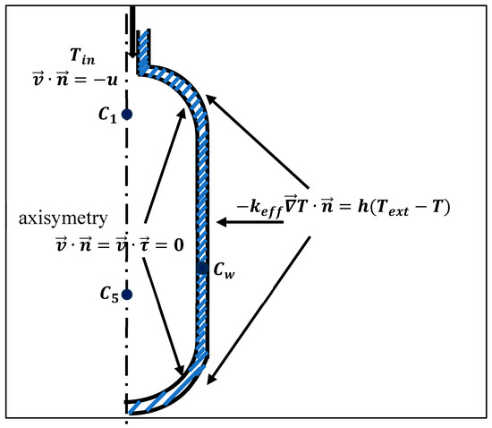
Figure 1.
Experimental locations and boundary conditions associated with the system of equations.
- Fluid inlet (top boundary): Dirichlet conditions for velocity and temperature.
- Hydrogen–steel interface: Continuity of thermal flux and no-slip condition for the gas phase velocity.
- Outer cylinder: Convective heat flux boundary condition.
Experimental studies aimed at setting the hydrogen injection velocity or flow rate have shown that precise control remains challenging, as reflected in the complexity of the flow rate expressions. However, empirical data consistently reveal a linear pressure profile during the injection phase. Based on these observations, the mass flow rate of injection is defined according to the following Equation (10):
where is the total mass of injected hydrogen and is the injection duration. This approach offers both practical utility and theoretical coherence by ensuring a controlled, uniform injection process consistent with empirical pressure observations. Furthermore, it constitutes a methodological contribution to the field of hydrogen adsorption research, introducing a simplified yet robust framework for defining injection parameters that enhances experimental reproducibility and facilitates direct comparison of results.
2.4. Modified Dubinin–Astakhov (DA) Model for Hydrogen Adsorption
To close the system of Equations (1), (4), and (6) the adsorbed amount calculated from the Dubinin–Astakhov isotherm model provides the necessary source terms for the species and energy transport equations, coupling the thermodynamic adsorption behavior with the macroscopic flow dynamics. The D-A model describes H2 adsorption in microporous materials (e.g., activated carbons, MOFs) by correlating the adsorbed amount with temperature and pressure . The principal modification to the original D-A model is that the parameter named as characteristic free energy of adsorption, usually symbolized with e, was replaced with the expression [31]:
- : Adsorbed amount (mol/kg);
- : Maximum adsorption capacity (saturation limit);
- : Material-specific constants (linked to adsorbent–adsorbate interactions);
- : Universal gas constant;
- Saturation pressure of .
The coefficient is material-dependent and can be adjusted according to the specific MOF under investigation. Notably, has been established as the optimal value for modeling hydrogen adsorption in both MOF-5- and activated carbon, consistent with prior experimental validations [18,32].
The values of , , , and are summarized in Table 2 for each adsorbent bed employed in this work.
Table 2.
Dubinin–Astakhov model parameters.
Based on the modified Dubinin–Astakhov model, the isosteric heat of adsorption is calculated as follows [18]:
3. Numerical Method, Grid Invariance, and Validation
3.1. Numerical Method
The coupled partial differential equations governing hydrogen adsorption were solved using Comsol Multiphysics 5.6 based on the Finite Element Method (FEM) with specialized discretization schemes. Temperature was approximated using linear Lagrange elements (), while quadratic elements () were employed for pressure discretization to better capture its sharper gradients. The global system was solved using a scaled approach with a tolerance factor of 0.1 for convergence criteria. Time integration was performed via the Backward Differentiation Formula (BDF) method with free order selection, allowing adaptive temporal resolution. A fully coupled Newton–Raphson scheme was implemented with a constant damping factor of to ensure robust convergence. The Jacobian matrix was updated at each timestep to maintain numerical accuracy throughout the transient solution. The resulting linear systems were handled by the MUMPS (MUltifrontal Massively Parallel Sparse) direct solver, chosen for its stability with ill-conditioned systems typical of adsorption problems. Initial conditions were implemented as nodal values corresponding to the pre-adsorption state , while the boundary conditions included the following: (1) Dirichlet conditions for hydrogen supply, (2) Neumann flux conditions for temperature , and (3) symmetry conditions where applicable. This numerical framework successfully captured the strong thermophysical coupling between the adsorbed phase (described by the modified Sips isotherm) and free gas dynamics while maintaining mass and energy balance.
3.2. Grid Invariance and Validation
The computational mesh consists of 3581 elements, comprising 1574 triangles and 2007 quadrangular elements, with the quadrangular elements predominantly situated at the interface and outer cylinder. A mesh refinement consisting of eight layers and stretching factor of 1.2 was applied at the hydrogen–stainless steel interface (Figure 2). This mesh represents the optimal configuration identified, balancing element count and result invariance.
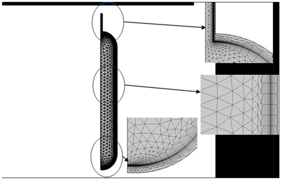
Figure 2.
Finite element mesh of hydrogen storage tank.
The numerical model of hydrogen adsorption was rigorously validated against experimental data from Xiao et al. (2013) [32]. Six thermocouples were placed along the axisymmetric axis , with two additional thermocouples positioned at the wall and midway between the axis and the wall to monitor the temporal evolution of temperature. With the exception of the point nearest the inlet (), the five remaining points exhibit identical temperature profiles. For this reason, only three measurement locations were selected: , , and , including mean system pressure and temperature , adsorbed mass values , and free hydrogen gas mass . The experimental conditions are presented in Table 3. Since the work focuses mainly on the mass of H2 adsorbed, only the injection and dormancy stages will be considered.
Table 3.
Experimental conditions of the process.
Table 4 presents a quantitative comparison between the experimental data and simulation results for key parameters of the adsorption process. The root mean square error (RMSE), mean absolute percentage error (MAPE), and the maximum relative error were used as indicators of model accuracy.
Table 4.
Quantitative comparison between experimental and simulated results.
For the adsorbed hydrogen mass , the model shows strong agreement with experiments, with an RMSE of , a MAPE of , and a maximum relative error of Similarly, the free gas mass was well predicted, although slightly higher deviations were noted (MAPE of , max error ).
A qualitative and quantitative comparison is illustrated in Figure 3 and Table 4 respectively. The average temperature and wall temperature were both accurately captured, with RMSE values of and , and extremely low MAPE values ( and , respectively). The pressure () predictions were also reliable, with a MAPE of 2.34% and a maximum error of 4.42%.
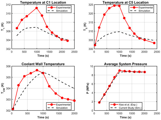
Figure 3.
Model validation (temperature field and pressure).
As for the local temperatures at two selected points, and , the model yielded RMSE values of and , and MAPE values of and , respectively, indicating slightly larger but still acceptable discrepancies, particularly at .
Overall, for a study aimed at evaluating global quantities such as , , and , the agreement between the model and experimental results is satisfactory (Figure 4). The discrepancies observed in local temperature values can be attributed to the simplified velocity model adopted, specifically the use of Darcy’s law for flow prediction in the porous medium.
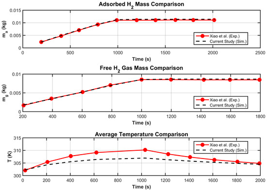
Figure 4.
Model validation (adsorbed and free H2 and average temperature).
Overall, the results confirm the robustness of the CFD model in reproducing the experimental behavior across thermal, mass, and pressure variables, validating its suitability for further optimization and design analyses.
4. Parametric Study
4.1. Effect of Material Properties
Simulation results for H2 storage using two MOF-5 configurations (powdered and compacted forms) are presented herein, with material characteristics provided in Table 2. Consistent with the activated carbon trials, identical boundary conditions were applied. The time-dependent profiles of system pressure and adsorbed H2 mass appear in Figure 5 and Figure 6.
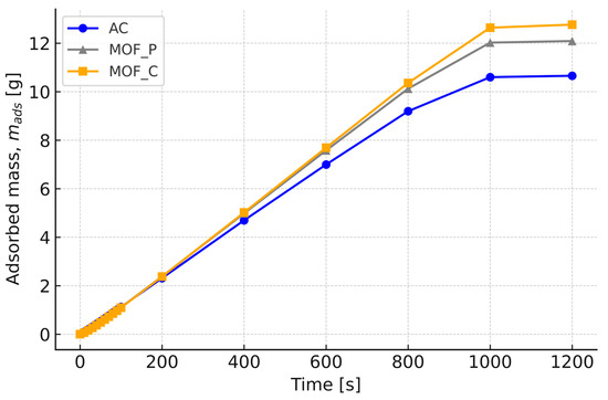
Figure 5.
H2 mass adsorbed for compact and powder MOF-5 and carbon.
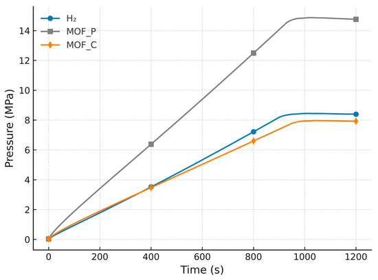
Figure 6.
Pressure profile comparison between compact and powder MOF-5 and carbon.
The results demonstrate that compact MOF-5 (MOF-5_C) achieves the highest H2 uptake (12 g) while operating at the lowest equilibrium pressure (7 MPa), outperforming both powder MOF-5 (MOF-5_P) and AC . This superior performance stems from MOF-5_C’s optimized pore hierarchy, which balances high capacity with efficient mass transport, unlike MOF-5_P, where kinetic limitations arise from particle diffusion resistance. Notably, MOF-5_C’s 20% higher capacity than MOF-5_P and 40% lower pressure requirement than AC challenge conventional assumptions, favoring powdered adsorbents. The compacted MOF-5’s structural integrity also offers practical advantages, including reduced energy penalties for compression (~25% savings vs. MOF-5_P) and mitigated particle fluidization risks, critical for industrial applications. These findings position MOF-5_C as the optimal candidate for systems prioritizing volumetric efficiency.
4.2. Effect of “Temperature and Flow Rate” Injection
The superior performance demonstrated in 4.1 motivated the selection of comapctMOF-5 for systematic optimization of hydrogen adsorption through parametric variation in injection conditions , targeting maximal H2 uptake.
The results are summarized in Table 5. The data reveal that adsorption capacity remains relatively stable () across all tested conditions, with maximal value attributed to couple , indicating limited sensitivity to and variations within these ranges. However, subtle trends emerge: (1) shorter injection times paired with lower temperatures tend to marginally enhance adsorption ), while (2) longer durations at higher temperatures also achieve comparable performance . Notably, the weak correlation between and operational parameters suggests that MOF-5C’s adsorption is predominantly governed by intrinsic material properties (e.g., pore structure, surface chemistry) rather than injection conditions in these ranges. For practical applications, this implies flexibility in system design, e.g., prioritizing faster cycles at ambient temperatures without significant capacity loss. Further optimization should focus on material modification (e.g., doping, activation) rather than operational parameter tuning alone.
Table 5.
Mass adsorbed of hydrogen for different temperature and time injection.
5. Conclusions and Perspectives for Future Work
A CFD model of hydrogen adsorption in porous materials is presented. It is based on the conservation equations (mass, momentum, and energy) coupled with a modified Dubinin–Astakhov model to describe adsorption kinetics. The system was solved using the finite element method. Model validation showed good agreement between simulation results and experimental data. The optimization phase focused on selecting suitable adsorbent materials and identifying the optimal injection conditions to ; that maximize the adsorbed hydrogen mass. The obtained results showed that MOF-5 achieves the highest H2 uptake while operating at the lowest equilibrium pressure (7 MPa). yielded the highest adsorbed hydrogen mass, reinforcing previous studies that recommend conducting the adsorption process at low temperatures. This result confirms the strong influence of thermal conditions on adsorption performance and supports the strategic design of operating parameters to enhance storage efficiency, MOF-5_C safety, and operational cost reduction, though further research is needed to validate long-term cycling stability and scale-up feasibility. For future work, exploring binder-enhanced MOF-5_C formulations and hybrid MOF-5-AC systems could unlock additional performance gains.
Author Contributions
Conceptualization, A.O. and B.M.; software, A.O.; validation, A.O.; formal analysis, A.O. and B.M.; writing—original draft preparation, A.O. and B.M.; writing—review and editing, A.O.; visualization, A.O. All authors have read and agreed to the published version of the manuscript.
Funding
This research received no external funding.
Data Availability Statement
The references for all the data used are cited in the article.
Conflicts of Interest
The authors declare no conflict of interest.
Nomenclature
| specific heat capacity | |
| particle diameter of adsorbent | |
| heat transfer coefficient | |
| thermal conductivity | |
| molecular mass of hydrogen | |
| mass of adsorbed phase hydrogen | |
| mass of gas phase hydrogen | |
| total mass of hydrogen in tank | |
| absolute adsorption amount per unit adsorbent | |
| limit adsorption amount per unit adsorbent | |
| pressure | |
| limited pressure | |
| adsorption heat | |
| universal gas constant | |
| rate, of hydrogen transfer from gas phase to adsorbed phase | |
| temperature | |
| Darcy velocity vector | |
| isosteric heat of adsorption | |
| Greek symbols | |
| enthalpic factor | |
| entropic factor | |
| density | |
| permeability of porous material | |
| dynamic viscosity | |
| bed porosity | |
| Subscript | |
| A | adsorbent |
| Ext | exterior or ambient |
| Int | initial |
| Inj | injection |
| Eff | effective |
| P | particles |
| G | gas phase |
References
- Arsad, A.Z.; Hannan, M.A.; Al-Shetwi, A.Q.; Begum, R.A.; Hossain, M.J.; Ker, P.J.; Mahlia, T.I. Hydrogen electrolyser technologies and their modelling for sustainable energy production: A comprehensive review and suggestions. Int. J. Hydrogen Energy 2023, 48, 27841–27871. [Google Scholar] [CrossRef]
- Al Ghafri, S.Z.; Munro, S.; Cardella, U.; Funke, T.; Notardonato, W.; Trusler, J.P.M.; Leachman, J.; Span, R.; Kamiya, S.; Pearce, G.; et al. Hydrogen liquefaction: A review of the fundamental physics, engineering practice and future opportunities. Energy Environ. Sci. 2022, 15, 2690–2731. [Google Scholar] [CrossRef]
- Nalla, A.A.; Nachtane, M.; Gu, X.; El Alami, M.; Gounni, A. Advances in numerical modeling and experimental insights for hydrogen storage systems: A comprehensive and critical review. J. Energy Storage 2025, 128, 117206. [Google Scholar] [CrossRef]
- Harrat, S.; Briki, C.; Sahli, M.; Settar, A.; Chetehouna, K.; Jemni, A. Experimental investigation of the hydrogen storage capacity in LaNi3.6Al0.4Mn0.3Co0.7 alloy. Int. J. Hydrogen Energy 2024, 77, 33–39. [Google Scholar] [CrossRef]
- Chen, L.; Ting, V.P.; Zhang, Y.; Deng, S.; Li, S.; Yin, Z.; Wang, F.; Wang, X. Modeling adsorption-based hydrogen storage in nanoporous activated carbon beds at moderate temperature and pressure. Int. J. Hydrogen Energy 2025, 122, 159–179. [Google Scholar] [CrossRef]
- Zeleňák, V.; Saldan, I. Factors affecting hydrogen adsorption in metal-organic frameworks: A short review. Nanomaterials 2021, 11, 1638. [Google Scholar] [PubMed]
- Umar, A.A.; Hossain, M.M. Hydrogen storage via adsorption: A review of recent advances and challenges. Fuel 2025, 387, 134273. [Google Scholar] [CrossRef]
- Chibani, A.; Boucetta, C.; Haddad, M.A.N.; Merouani, S.; Adjel, S.; Merabet, S.; Laidoudi, H.; Bougriou, C. Effect of fin material type and reactor inclination angle on hydrogen adsorption process in large-scale activated carbon-based heat storage system. J. Energy Storage 2024, 98, 113091. [Google Scholar] [CrossRef]
- Yao, J.; Zhu, P.; Guo, L.; Duan, L.; Zhang, Z.; Kurko, S.; Wu, Z. A continuous hydrogen absorption/desorption model for metal hydride reactor coupled with PCM as heat management and its application in the fuel cell power system. Int. J. Hydrogen Energy 2020, 45, 28087–28099. [Google Scholar] [CrossRef]
- Ye, Y.; Ding, J.; Wang, W.; Yan, J. The storage performance of metal hydride hydrogen storage tanks with reaction heat recovery by phase change materials. Appl. Energy 2021, 299, 117255. [Google Scholar] [CrossRef]
- Wang, J.; Melideo, D.; Ferrari, L.; Pardelli, P.T.; Desideri, U. Study on the influence mechanism of fin structure on the filling performance of cold adsorption hydrogen storage tank. Int. J. Hydrogen Energy 2024, 94, 897–911. [Google Scholar] [CrossRef]
- Huang, X.; Jin, S.; Yu, M.; Li, Y.; Li, M.; Chen, J. Numerical studies of a new device for a cryo-adsorption hydrogen storage system. Int. J. Hydrogen Energy 2024, 82, 1051–1059. [Google Scholar] [CrossRef]
- Peng, C.; Long, R.; Liu, Z.; Liu, W. Improving adsorption hydrogen storage performance via triply periodic minimal surface structures with uniform and gradient porosities. Int. J. Hydrogen Energy 2024, 53, 422–433. [Google Scholar] [CrossRef]
- Briki, C.; Dunikov, D.; Almoneef, M.M.; Romanov, I.; Kazakov, A.; Mbarek, M.; Abdelmajid, J. Experimental and Theoretical Studies of Hydrogen Storage in LaNi4.4Al0.3Fe0.3 Hydride Bed. Materials 2023, 16, 5425. [Google Scholar] [CrossRef]
- Elkhatib, R.; Louahlia, H. Metal hydride cylindrical tank for energy hydrogen storage: Experimental and computational modeling investigations. Appl. Therm. Eng. 2023, 30, 120756. [Google Scholar] [CrossRef]
- Shabbani, H.J.K.; Abd, A.A.; Hasan, M.M.; Helwani, Z.; Kim, J.; Othman, M.R. Effect of thermal dynamics and column geometry of pressure swing adsorption on hydrogen production from natural gas reforming. Gas Sci. Eng. 2023, 116, 205047. [Google Scholar] [CrossRef]
- Mahmoodi, F.; Rahimi, R. Experimental and numerical investigating a new configured thermal coupling between metal hydride tank and PEM fuel cell using heat pipes. Appl. Therm. Eng. 2020, 178, 115490. [Google Scholar] [CrossRef]
- Xiao, J.; Hu, M.; Cossement, D.; Bénard, P.; Chahine, R. Finite element simulation for charge–discharge cycle of cryo-adsorptive hydrogen storage on activated carbon. Int. J. Hydrogen Energy 2012, 37, 12947–12959. [Google Scholar] [CrossRef]
- Xiao, J.; Peng, R.; Cossement, D.; Bénard, P.; Chahine, R. CFD model for charge and discharge cycle of adsorptive hydrogen storage on activated carbon. Int. J. Hydrogen Energy 2013, 38, 1450–1459. [Google Scholar] [CrossRef]
- Xiao, J.; Peng, R.; Cossement, D.; Bénard, P.; Chahine, R. Heat and mass transfer and fluid flow in cryo-adsorptive hydrogen storage system. Int. J. Hydrogen Energy 2013, 38, 10871–10879. [Google Scholar] [CrossRef]
- Melideo, D.; Ferrari, L.; Pardelli, P.T. CFD simulation of hydrogen storage: Adsorption dynamics and thermal management in cryogenic tanks. Int. J. Hydrogen Energy 2025, 179, 149261. [Google Scholar] [CrossRef]
- Klepp, G. Modelling activated carbon hydrogen storage tanks using machine learning models. Energy 2024, 306, 132318. [Google Scholar] [CrossRef]
- Wang, C.-S.; Brinkerhoff, J. Low-cost lumped parameter modelling of hydrogen storage in solid-state materials. Energy Convers. Manag. 2022, 251, 115005. [Google Scholar] [CrossRef]
- Xiao, J.; Li, Q.; Cossement, D.; Bénard, P.; Chahine, R. Lumped parameter simulation for charge-discharge cycle of cryo-adsorptive hydrogen storage system. Int. J. Hydrogen Energy 2012, 37, 13400–13408. [Google Scholar] [CrossRef]
- Singh, A.; Maiya, M.P.; Murthy, S.S. Effects of heat exchanger design on the performance of a solid state hydrogen storage device. Int. J. Hydrogen Energy 2015, 40, 9733–9746. [Google Scholar] [CrossRef]
- Wang, J.; Melideo, D.; Ferrari, L.; Pardelli, P.T.; Desideri, U. Integrated targeted pre-cooling tubes and fins for enhanced hydrogen adsorption in activated carbon storage tank. Int. J. Hydrogen Energy 2025, 146, 149942. [Google Scholar] [CrossRef]
- Arslan, B.; Ilbas, M.; Celik, S. Experimental analysis of hydrogen storage performance of a LaNi5–H2 reactor with phase change materials. Int. J. Hydrogen Energy 2023, 48, 6010–6022. [Google Scholar] [CrossRef]
- Richard, M.A.; Cossement, D.; Chandonia, P.A.; Chahine, R.; Mori, D.; Hirose, K. Preliminary evaluation of the performance of an adsorption-based hydrogen storage system. AIChE J. 2009, 55, 2985–2996. [Google Scholar] [CrossRef]
- Nicolas, V.; Sdanghi, G.; Mozet, K.; Schaefer, S.; Maranzana, G.; Celzard, A.; Fierro, V. Numerical simulation of a thermally driven hydrogen compressor as a performance optimization tool. Appl. Energy 2022, 323, 119628. [Google Scholar] [CrossRef]
- Lopez, L.J.; Morales-Ospino, R.; Castro-Gutiérrez, J.; Sumbhaniya, H.O.; Sdanghi, G.; Dalí, S.G.; Celzard, A.; Fierro, V. Boosting hydrogen storage and release in MOF-5/graphite hybrids via in situ synthesis. Int. J. Hydrogen Energy 2025, 173, 151272. [Google Scholar] [CrossRef]
- Richard, M.A.; Bénard, P.; Chahine, R. Gas adsorption process in activated carbon over a wide temperature range above the critical point. Part 1: Modified Dubinin-Astakhov model. Adsorption 2009, 15, 43–51. [Google Scholar] [CrossRef]
- Xiao, J.; Hu, M.; Bénard, P.; Chahine, R. Simulation of hydrogen storage tank packed with metal-organic framework. Int. J. Hydrogen Energy 2013, 38, 13000–13010. [Google Scholar] [CrossRef]
Disclaimer/Publisher’s Note: The statements, opinions and data contained in all publications are solely those of the individual author(s) and contributor(s) and not of MDPI and/or the editor(s). MDPI and/or the editor(s) disclaim responsibility for any injury to people or property resulting from any ideas, methods, instructions or products referred to in the content. |
© 2025 by the authors. Licensee MDPI, Basel, Switzerland. This article is an open access article distributed under the terms and conditions of the Creative Commons Attribution (CC BY) license (https://creativecommons.org/licenses/by/4.0/).