Abstract
The use of liquid hydrogen (LH2) as an energy carrier is gaining traction across sectors such as aerospace, maritime, and large-scale energy storage due to its high gravimetric energy density and low environmental impact. However, the cryogenic nature of LH2, with storage temperatures near 20 K, poses significant thermodynamic and safety challenges. This review consolidates the current state of modelling approaches used to simulate LH2 behaviour during storage and transfer operations, with a focus on improving operational efficiency and safety. The review categorizes the literature into two primary domains: (1) thermodynamic behaviour within storage tanks and (2) multi-phase flow dynamics in storage and transfer systems. Within these domains, it covers a variety of phenomena. Particular attention is given to the role of heat ingress in driving self-pressurization and boil-off gas (BoG) formation, which significantly influence storage performance and safety mechanisms. Eighty-one studies published over six decades were analyzed, encompassing a diverse range of modelling approaches. The reviewed literature revealed significant methodological variety, including general analytical models, lumped-parameter models (0D/1D), empirical and semi-empirical models, computational fluid dynamics (CFD) models (2D/3D), machine learning (ML) and artificial neural network (ANN) models, and numerical multidisciplinary simulation models. The review evaluates the validation status of each model and identifies persistent research gaps. By mapping current modelling efforts and their limitations, this review highlights opportunities for enhancing the accuracy and applicability of LH2 simulations. Improved modelling tools are essential to support the design of inherently safe, reliable, and efficient hydrogen infrastructure in a decarbonized energy landscape.
1. Introduction
In response to growing global energy demands and the urgent need for low-carbon solutions, hydrogen has emerged as a pivotal energy carrier in the transition toward sustainable systems. Hydrogen (H2) offers distinct advantages due to its high gravimetric energy density (120 MJ/kg) and relatively low environmental impact [1]. Compared to compressed gaseous hydrogen (CGH2 at 700 bar), LH2 provides superior volumetric energy density (8 MJ/L vs. 5.6 MJ/L), making it particularly attractive for applications in aerospace, maritime transport, and large-scale energy storage [2]. Despite these benefits, the cryogenic nature of LH2—requiring storage at approximately 20 K (−253 °C)—introduces significant thermodynamic and safety challenges [3]. These include complex heat and mass transfer processes, phase transitions, and pressure dynamics, all of which are further complicated by LH2’s chemical properties such as high diffusivity, low ignition energy, and wide flammability limits. As a result, the safe and efficient handling, storage, and transfer of LH2 demand a deep understanding of interdependent physical phenomena and robust modelling approaches. Table 1 provides a comparison of key properties of different fuels, including CGH2 at 700 bar, LH2, natural gas (NG) at 250 bar, liquefied natural gas (LNG), and gasoline.

Table 1.
Comparison of safety- and efficiency-relevant properties of some energy carriers [1,2,4].
To date, no comprehensive review has systematically examined the modelling techniques used to simulate LH2 behaviour across its storage and transfer lifecycle. Existing studies often focus on isolated phenomena—such as heat ingress, boil-off gas (BoG) formation, or sloshing—without fully addressing the interconnected nature of these processes. This fragmentation limits the development of integrated models capable of supporting the design of inherently safe and efficient LH2 infrastructure.
This literature review aims to fill that gap by consolidating and critically analyzing modelling approaches across two principal domains:
- Thermodynamic behaviour within LH2 storage tanks;
- Multi-phase flow dynamics in storage and transfer systems.
Within these domains, the review explores seven focus areas: heat transfer, mass transfer (evaporation/condensation), thermal stratification and pressurization, venting and depressurization, sloshing, LH2 transfer operations, and flash boiling with pressure recovery. These phenomena are not independent; rather, they interact dynamically, influencing system performance and safety outcomes. Recognizing and modelling these interdependencies is essential for accurate simulation and practical application.
The objectives of this review are as follows:
- Map the current landscape of LH2 modelling techniques;
- Evaluate the extent of model validation against experimental data;
- Identify persistent knowledge gaps;
- Provide guidance for future research and model development.
By synthesizing insights from over six decades of research, this review contributes to the advancement of LH2 technologies and supports the development of safer, more reliable, and economically viable hydrogen systems in a decarbonized energy future.
2. State of the Art
This section provides an overview of insulation techniques of LH2 storage and transfer systems, followed by an introduction to the focus areas that are subject to the reviewed literature and the corresponding simulation models. Each focus area and the connected phenomena are thereafter presented in more detail. One of the main concerns when handling LH2 is the evaporation of the liquid phase due to unavoidable heat ingress. The evaporated LH2 is called boil-off gas (BoG) and is a driving factor of pressurization. Cryogenic tanks, commonly used to store substances such as LH2 or LNG, are typically constructed as double-walled containers. In the case of LH2 transfer pipes, this concept extends to double-walled piping. The space between the inner and outer wall (annular space) is filled with insulation material and, depending on the insulation material, maintained under vacuum. An overview of the different insulation materials is provided in a work by Claussner et al. [5]. The performance of the various insultation materials can be supplemented with additional efforts. A popular method to further improve the insulation characteristics is the deployment of vapour-cooled shields (VCS). A VCS is a thermal shield placed inside the multi-layer insulation (MLI) of a cryogenic tank [6]. It uses cold hydrogen vapour, which is already evaporating from the stored LH2, to intercept and absorb some of the incoming heat before it reaches the inner wall of the cryotank. Studies show VCS can cut heat flux by up to 70%. While multiple VCS layers can improve performance, the benefits diminish beyond two shields [6]. A practical drawback of VCS is increased complexity of tank design. This will affect developmental and manufacturing costs. Further investigation is needed to determine whether this additional cost could be offset—or even surpassed—by savings resulting from improved dormancy behaviour, including a review of experimental studies. Active cooling of an LH2 tank can be achieved through a two-stage cryocooler setup. A prototype by NASA uses a first stage, a 90 K cryocooler, that is paired with a tube-on-shield (TOS) broad-area cooling (BAC) heat exchanger that intercepts and removes incoming heat before it reaches the propellant tank [7]. The second stage employs a 20 K cryocooler and a tube-on-tank (TOT) heat exchanger to extract heat directly from the LH2 liquid and ullage space, maintaining stable pressure and preventing boil-off [7].
Seven focus areas were identified during the review process. These individual areas were not strictly equivalent to one specific thermodynamic phenomenon but rather defined by the objective of the authors. In some cases, the area of focus incorporates many thermodynamic phenomena to explain a more complex condition or operational scenario.
The focus areas were divided into two main groups, thermodynamic behaviour of the storage tank and multi-phase flow in storage tank and pipelines:
- Thermodynamic behaviour of the storage tank:
- ○
- Heat transfer;
- ○
- Mass transfer including evaporation/condensation;
- ○
- Thermal stratification and pressurization;
- ○
- Venting and depressurization.
- Multi-phase flow:
- ○
- Sloshing;
- ○
- LH2 transfer;
- ○
- Flash boiling and pressure recovery.
Figure 1 shows the thermodynamic phenomena inside of LH2 storage tanks corresponding to the focus areas.
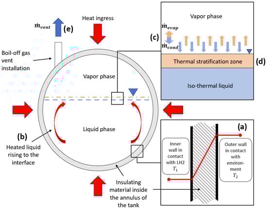
Figure 1.
Thermodynamic behaviour of LH2 storage tank and corresponding phenomena: (a) heat transfer into the tank through conduction; (b) heat transfer through natural convection; (c) evaporation and condensation at the interface; (d) thermal stratification, (e) venting and tank depressurization.
2.1. Heat Transfer
Heat transfer into the LH2 storage and transfer equipment plays a central role in leading to adverse effects limiting operability. Even though heat transfer is omnipresent in LH2 applications, this section focuses on the heat transfer into a storage tank. Heat transfer occurs through conduction, radiation, and convection. Heat conduction is the transfer of heat through direct molecular interactions. In fluids, it occurs via inelastic collisions in nonconducting solids through molecular (lattice) vibrations, and in metals via electron movement (conduction electrons) and molecular collisions [8]. It is the primary heat transfer mechanism in opaque solids, while transparent solids may also transfer heat via radiation. Conduction is quantified using Fourier’s law, with thermal conductivity determining efficiency. The law is based on two key quantities: temperature and heat flow, expressed as
where represents the rate of heat transfer across a temperature gradient , determined by thermal conductivity [9]. To calculate heat transfer by conduction through a plane wall, Fourier’s law of heat conduction applies where is the thickness of the wall:
The surface area of heat transfer is given by , and the wall temperatures at the inner and outer side are given by and , respectively. refers to the wall thickness. Figure 1a shows a schematic of the heat ingress into an LH2 tank, mainly through conduction. For LH2 applications, conduction heat transfer occurs through the wall of a tank or a pipe, even though the annulus contains insulation material. Furthermore, the support structure of the inner tank and cables for level and temperature sensors act as thermal bridges. Insulating materials like foams and fibres can reduce heat transfer by increasing path length and decreasing cross-sectional area [8]. In VMLI (vacuum multi-layer insulation) of LH2 tanks, spacers between the layers of insulation material are made from materials with low conductivity.
Convection is described as heat transfer involving both molecular motion and fluid transport. It is governed by Newton’s law of cooling and depends on the heat transfer coefficient, which is influenced by fluid properties, velocity, and flow shape [9]. Convection occurs through diffusion (due to gradients) and advection (bulk fluid motion). It can be natural (driven by density differences) or forced (using fans or pumps). Convection plays a crucial role in heating, cooling, and phase-change processes [9]. Newton’s law of cooling is described as
where represents the convection heat transfer coefficient [10], denotes the surface area exposed to the fluid, influencing the total heat exchange, and is the temperature difference between the surface and the surrounding fluid, which drives the heat transfer process [10]. Convection is part of the heat transfer inside the tank between the fluid in different sections of the tank, especially between the liquid and the vapour phases as interface-to-liquid and interface-to-vapour heat transfer [11]. The liquid in contact with the inner tank wall increases in temperature, decreases in density, and flows up toward the liquid–vapour interface as consequence of the gained buoyancy. The internal convection can be minimized if the insulating properties of the tank shell (inner wall, outer wall, and insulation inside the annulus) are enhanced. Figure 1b shows the schematic of an LH2 storage tank in which heat ingress resulted in natural convection from the bulk liquid to the liquid–vapour interface. Heat transfer through natural convection [12] may provoke thermal stratification (see Section 2.3).
Radiation heat transfer occurs as all materials emit energy in all directions, requiring no medium, unlike conduction and convection [9]. This allows energy transfer through a vacuum. Governed by the Stefan–Boltzmann law, radiation depends on surface properties like emissivity, absorptivity, transmissivity, and reflectivity. The heat transfer rate (power) by emitted radiation is determined by
where represents the Stefan–Boltzmann constant, the variable denotes the surface area of the object, is its absolute temperature in K, and represents the emissivity of the object, indicating how efficiently it emits radiation. Radiation spans different wavelengths, shifting to shorter, higher-energy wavelengths as temperature increases [9]. In LH2 applications, radiation manifests through the tank shell. External heat sources, such as the sun or accidental fires, can heat up the outer wall of an LH2 tank which then starts emitting heat radiation towards the inner wall through the insulation. The insulation plays a crucial role in minimizing heat transfer through radiation. Common practices to reduce heat ingress through radiation include the use of reflecting materials in the insulation. In the case of cryogenic LH2 tanks, radiation and conduction are the dominant forms of heat ingress, since heat transfer through convection is limited by the vacuum inside the annulus of the tank. The heat transfer mechanisms described here are not isolated; they directly influence mass transfer, thermal stratification, and pressurization, underscoring the need for integrated modelling approaches.
2.2. Mass Transfer Including Evaporation and Condensation
Depending on the filling level of the LH2 tank, as well as on the internal temperature and pressure, the LH2 is usually present in two phases: a gaseous and a liquid phase. The gaseous phase is often described as vapour phase or ullage. Due to thermodynamic processes, mainly resulting from heat ingress into the tank, condensation and evaporation at the vapour–liquid interface occur. This mass transfer happens simultaneously in both directions. Figure 1c shows a schematic of mass transfer at the vapour–liquid interface of an LH2 tank. D. Lee [13] developed a model for evaporation and condensation, assuming that phase change occurs based on a relaxation process. In this model, the mass transfer rate for evaporation is described as [13]:
The mass transfer rate for condensation is described as [13]:
where and represent the mass transfer rates due to evaporation and condensation, respectively. The parameter is the mass transfer coefficient, expressed with unit , and is often referred to as the relaxation parameter [13]. Furthermore, and denote the densities of the liquid and vapour phases. is the local temperature, while is the saturation temperature at which phase change occurs [13].
2.3. Thermal Stratification and Tank Pressurization
Thermal stratification in a cryogenic tank refers to the temperature distribution within the liquid column and the ullage space [14]. Thermal stratification and pressurization are emergent phenomena resulting from the interplay of heat and mass transfer, making their accurate prediction dependent on understanding these underlying processes. Thermal stratification of LH2 in cryogenic tanks occurs due to heat ingress into the tank over time. As heat enters, it forms a natural convection boundary layer in the liquid near the tank wall. This causes warmer liquid to rise from the bulk region near the tank walls to the liquid–vapour interface due to buoyant forces, creating a distinct warm liquid zone at the top of the iso-thermal bulk liquid [14]. The gradual increase in the thickness of this warm zone leads to an vertical temperature gradient in the liquid, known as thermal stratification [15]. Figure 1d shows a schematic of a thermal stratification layer build-up in an LH2 tank. The warmer upper layer of the liquid phase starts to evaporate to reach thermodynamical equilibrium, transferring mass and heat into the vapour phase. However, heat and mass are transferred in parallel from the vapour phase to the liquid in the form of condensation. LH2 tanks for large-scale storage can be considered closed systems when all valves and ports are closed, which results in pressurization when the contents of the tank are warming up and starting to expand. Furthermore, pressurization leads to more condensation at the interface where the vapour is colder than the rest of the vapour space. Due to the vertical temperature gradient, it is very difficult to accurately predict temperature and pressure evolution over time. In stationary tanks, temperature stratification cannot be avoided. However, the formation can be slowed down by limiting heat ingress by improving the tanks insulation. Tanks with installations for active cooling could utilize spray-cooling to constantly introduce subcooled droplets of LH2 at the top of the tank into the vapour phase. LH2 is subcooled when the temperature is below the saturation point at a certain pressure [16]. Mobile tank systems could take advantage of the effects of sloshing, constantly mixing the fluid inside of the tank to avoid the formation of stratified layers. However, the efficiency of measures to avoid stratification should be subject to investigations with the purpose of evaluating economic viability.
2.4. Venting and Tank Depressurization
Venting (releasing hydrogen from its containment into the atmosphere) is initiated when the internal tank pressure has increased above the set pressure of the release device, which can be achieved by an actively controlled or a passively activated pressure-release valve (PRV). Venting can be the result of self-pressurization or active pressurization through the introduction of gas or through heating [17]. Filling procedures can make active venting necessary when the filled hydrogen is not subcooled or the receiving tank’s initial internal temperature is too high, thus making excessive evaporation unavoidable. In both cases, excess gas needs to be released to lower the internal pressure and temperature and to continue with the filling procedure. In summary, discharge of LH2 from the tank leads to depressurization and to cooling. Figure 1e shows a schematic of the upper section of an LH2 tank with a vent mast and the corresponding mass flow during venting operation. Understanding venting is relevant for the operation of LH2 tanks, not just for safety reasons, but also for the efficient transfer process when receiving or supplying LH2. This concept extends to the depressurization behaviour, which is relevant during outflow when LH2 consumers, such as fuel cells or internal combustion engines, are actively draining the supplying tanks content.
2.5. Sloshing
Sloshing is the movement of fluids, such as cryogenic propellants, within a storage tank, which becomes more pronounced in low-gravity environments. Sloshing can be caused by slight vibrations due to the low viscosity of LH2 and it disturbs the thermodynamic equilibrium within the tank by mixing high-temperature vapour with subcooled fluid. This can cause a rapid pressure drop and ullage collapse [18]. In space travel, it affects the control of pressurants. A pressurant is intentionally evaporated cryogenic fuel that is used to move the liquid propellant and to keep the internal pressure of a tank high enough to operate the consumers, such as rocket engines [19]. Sloshing, however, can lead to changes in temperature and pressure due to gas condensation on the vapour–liquid interface and increases in BoG formation [20]. Sloshing increases BoG formation in two main ways:
- Heat transfer—Sloshing dissipates kinetic energy into the tank system, transferring heat and accelerating fuel evaporation.
- Increased surface area—The motion increases the liquid–vapour interface, enhancing evaporation.
Sloshing effects in LH2 are not well studied compared to LNG, where previous research has linked sloshing to pressure and temperature variations. To limit the negative effects of sloshing, the movement of the tank should be kept minimal. However, for mobile applications, this is not feasible. Instead, so-called baffles are installed inside the tank to slow down fluid movement. Baffles can, under certain circumstances, act as thermal bridges, accelerating heat ingress into the tank and therefore promoting stratification, particularly in operational scenarios in which the tank is not moving. However, this depends on the insulation design of the tank. Furthermore, the initial chill-down of a warm tank can be more time- and energy-intensive due to the additional thermal capacity of the baffles. The thermodynamic effects of sloshing on LH2 are underexplored, making it a critical area for further research, especially in designing fuel-efficient and cost-effective LH2 carriers [21]. Figure 2 shows a schematic cross section of an LH2 tank with baffles to mitigate sloshing of the liquid phase inside.
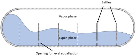
Figure 2.
Schematic cross section of an LH2 tank with sloshing liquid and installed baffles.
2.6. LH2 Transfer Operations
LH2 transfer operations refer to the processes of flowing LH2 from one container to another, typically involving pipelines, storage tanks, or transport vessels. Transfer operations involve complex multi-phase flow, where heat ingress, evaporation, and pressure changes interact dynamically, requiring holistic modelling to capture these interdependencies. There are several methods for transferring LH2 efficiently. Pump transfer relies on cryogenic pumps to move LH2 under controlled pressure, while pressure-driven transfer utilizes differential pressure to push LH2 from one vessel to another. If the transferred fluid consists of a gas phase and a liquid phase, the flow is considered as multi-phase. Especially at the beginning of a transfer process, when the pipe is not entirely cooled down yet, multi-phase flow occurs due to evaporation. This formation of gas has a significant negative impact on the filling procedure of a receiving tank, since the presence of a gas phase leads to necessary venting or energy consumption through active cooling. Furthermore, the geometry of LH2-containing transfer components influences vapour formation. Generally, turbulence and thereby friction can be promoted by certain geometries, causing pressure drop and heat ingress and therefore enhancing evaporation. To what extend existing models underpredict the influence of pipe geometry should be subject to separate analysis. Figure 3 shows a schematic cross section of an LH2 transfer pipe with a developed multi-phase-flow.
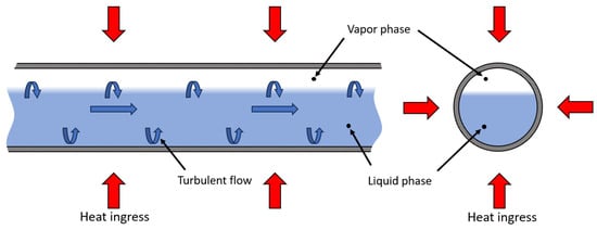
Figure 3.
Schematic cross section of an insulated pipe with a turbulent two-phase flow of LH2 inside.
2.7. Flash Boiling and Pressure Recovery
Flashing, or flash evaporation, occurs when a liquid boils due to a sudden reduction in pressure. Several key factors influence this phenomenon, including the initial temperature, overheating temperature, pressure reduction rate, and liquid level [22]. Thermal stratification plays a significant role in flashing, with the hot gas–liquid interface boiling first, followed by vapour generation at the bottom of the vessel. This process pushes up the liquid surface, ultimately leading to pressure recovery [22]. Figure 4 shows the phase diagram of H2, with the red arrow indicating a sudden pressure drop at equilibrium leading to evaporation.
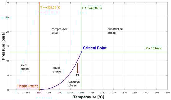
Figure 4.
Phase diagram of H2.
3. Methodology
A narrative literature review approach was selected in this study to provide an overview of existing modelling approaches to simulate LH2 thermo- and fluid dynamics in storage and transfer components. A narrative literature review is a versatile methodology widely used in research to synthesize existing literature, provide overviews, and critique findings in a coherent manner. It is particularly effective when addressing complex or multifaceted topics that require flexibility and interpretative depth [23]. This literature review was carried out following the key steps introduced in Figure 5.
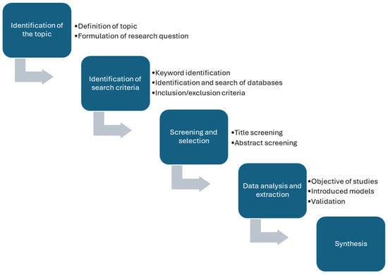
Figure 5.
Key steps adapted to conduct a narrative review.
The key steps were derived from Pickering and Byrne [24] and adapted for the purpose of conducting a structured narrative review. As a first step, a topic was selected and related research questions were considered. The topic was defined as “Review of Modelling Approaches for LH2 Thermodynamics during Storage and Transfer”. The objective was to provide an overview of relevant thermodynamic phenomena, problems, and different modelling approaches for LH2 dynamics in the corresponding systems and components. This review addresses the following research questions:
- What thermodynamic phenomena are covered by the existing literature for LH2?
- What are the proposed modelling approaches to simulate these phenomena?
- Are the proposed approaches validated?
- Why are certain models not validated/is there an identifiable knowledge gap or need for data?
The literature review utilized a comprehensive search strategy across multiple scientific databases to ensure a broad overview. Key sources included Scopus, Google Scholar, and the NASA archive, the latter offering access to an extensive collection of studies dating back to the 1960s, many of which are not available elsewhere. The search terms and keywords focused on topics central to the research:
- Liquid hydrogen or LH2;
- Model or Modelling;
- Simulation;
- Pressurization;
- Storage;
- Tank;
- Thermodynamic;
- Fluid dynamics.
Studies were included or excluded based on specific criteria:
- Publications in languages other than English and German were excluded;
- Models referring to substances other than LH2 were excluded;
- Excluded subject areas included the following terms:
- a.
- Medicine;
- b.
- Chemistry;
- c.
- Computer science;
- d.
- Social science;
- e.
- Pharmacology;
- f.
- Environmental science;
- g.
- Biology.
- Excluded keywords included the following terms:
- a.
- Combustion;
- b.
- Diffusion;
- c.
- Oxygen;
- d.
- Helium;
- e.
- Rocket engine;
- f.
- Ballistics;
- g.
- Viscosity;
- h.
- Cavitation;
- i.
- Catalyst.
The criteria presented in this section applied to the use of Scopus as search tool exclusively. Literature found in the other databases or sources was screened for exclusion criteria via title and abstract screening. The screening and selection process involved several systematic steps. Initially, title screening was conducted to filter out unrelated studies. This was followed by an abstract screening to determine the purpose and scope of the studies, assessing whether they introduced simulation models and to make sure that none of the exclusion criteria were met. The full-text analysis, extraction, and synthesis process began with an initial document overview, where each paper was scanned to identify its key focus by reviewing the abstract, introduction, and conclusion. Following this, a focused reading was conducted, analyzing specific sections relevant to the research question. After focused reading, the synthesis stage categorized studies based on the thermodynamic phenomena they addressed. For each phenomenon, relevant papers were assigned, and their modelling approaches were examined in detail, including simulation techniques, software used, and LH2 storage components such as tanks or pipes. Lastly, the models were screened for whether they were validated or not, and if a model lacked validation, an effort was made to determine the reason. Identified knowledge gaps, theoretical advances, and consequently recommendations for future research were included.
4. Modelling of LH2 Thermal Dynamic Behaviour
In total, 81 papers that focus on one or more of the seven topics described in Section 2 were identified and included in this study. The analyzed sources have been published over a period of 64 years, with the oldest work dating back to 1961. In Figure 6, an overview of the distribution of the analyzed papers over the years is provided. The literature review was concluded in January 2025. In recent years, there has been a trend of an increasing number of publications connected to the topic of this review. This growing interest in LH2 modelling underscores the relevance of LH2 thermodynamics and corresponding modelling approaches.
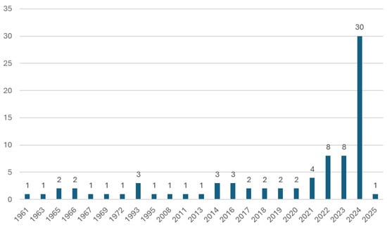
Figure 6.
Number of papers over the years falling within the seven focus areas described in Section 2.
Most of the papers (56) focused on the modelling of thermodynamic behaviour of LH2 in storage tanks; 24 papers focused on the modelling of the behaviour during multi-phase flow and in pipelines. Figure 7 presents the numbers of papers for each focus area, indicating how many of the corresponding models were validated.
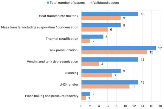
Figure 7.
Number of models and validated models per focus area.
The analyzed literature revealed a wide range of modelling approaches:
- General analytical models;
- Lumped-parameter models (0D/1D models);
- Empirical and semi-empirical models;
- Computational fluid dynamics (CFD) models (2D/3D);
- Machine learning (ML) and artificial neural network (ANN) models;
- Numerical multidisciplinary simulation models.
Figure 8 provides an overview of the amount of different modelling approaches that were found in the analyzed papers.
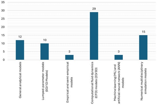
Figure 8.
Amount of different modelling approaches.
Some of the presented models are combinations or the paper introduces multiple approaches. Therefore, the summed-up number of modelling approaches does not fit the total number of papers.
4.1. Models Focusing on Thermodynamic Behaviour in Storage Tanks
4.1.1. Models Focusing on Heat Transfer
Huntley et al. [25] conducted research on the thermal behaviour of LH2 in a tank when subjected to heating from the wall and bottom. They introduced an experimental and analytical model combined with dimensionless parameterization. The models were compared with each other. This experimental study on LH2 behaviour in a heated tank at constant pressure revealed several key findings. A predictive analysis successfully estimated temperature stratification trends with increasing wall heat flux [25]. L. Wang et al. [26] conducted a axisymmetric CFD investigation on how varying gravity conditions influence the thermodynamic characteristics of LH2 tanks. The developed CFD model incorporates multicomponent effects and phase-change dynamics using the Schrage equation and Dalton’s law. Due to lack of data, the model was not validated [26]. J. W. Jiang et al. [6] simulated the transient behaviour of a MLI LH2 tank coupled with a VCS. The model accounted for heat transfer into the tank, pressurization, and the effects of active cooling. The model was validated using experimental data from NASA’s Multipurpose Hydrogen Test Bed (MHTB) [27]. A CFD model based on the VoF method (volume of fluid method) to determine phase-change coefficients for evaporation and condensation was developed by R. Lv et al. [28]. The study explores scale effects on self-pressurization in LH2 tanks under normal- and microgravity. Grid-independence tests confirm grid selection for 16 cases, ensuring numerical reliability and efficiency [28]. F. Ustolin et al. [29] developed an analytical model based on thermodynamic equations to estimate the time to failure for a cryogenic LH2 tank exposed to fire [29]. The model accounts for the heat transfer into the tank, the pressurization behaviour, the mass transfer at the liquid–vapour interface, and the release rate of the BOG. It was validated against experimental results. Due to missing experimental details, assumptions were made regarding the pressure-relief valve section area and MLVI thermal conductivity [29]. Furthermore, F. Ustolin et al. [30] developed a 2D CFD model to analyze the thermal behaviour of an LH2 tank exposed to an external fire. The heat transfer into the tank, the mass transfer at the liquid–vapour interface, and the pressurization behaviour were investigated [30]. The model was validated against experimental data, showing reasonable agreement despite measurement uncertainties [31]. Sun et al. [32] developed a model to analyze the heat transfer into an LH2 storage tank including mass transfer at the liquid–vapour interface, tank self-pressurization, and the evaporation rate. The model is a numerical quasi-2D model, which is essentially a hybrid approach where heat transfer is modelled as one-dimensional (1D) in certain directions and two-dimensional (2D) in others, simplifying full 3D modelling. The validation was conducted by comparing the model predictions with experimental data from four distinct cryogenic storage tanks [32]. Wang et al. [11] modelled and compared the thermodynamic behaviour of LH2 tanks for maritime transport with different insulation types at varying filling levels. Therefore, an analytical model was presented. The model was validated through comparisons with experimental data from LH2 and liquefied natural gas (LNG) tanks. Key parameters affecting pressure rise and vapour temperature predictions were adjusted to match experimental results. The model showed good agreement with vapour temperature measurements across different filling levels, though initial pressure rise predictions were slightly overestimated at higher fill levels [11]. For heat transfer in insulation, the model was compared against a chill-down experiment conducted on a 208 m3 LH2 spherical tank at Los Alamos National Laboratory [11]. Parello et al. [33] conducted research on design and integration of LH2 tanks for aircraft by developing a multi-phase thermodynamic model using phyton, which accounts for heat transfer into the tank and the resulting boil-off. The model integrates thermodynamic and structural analyses to assess tank performance during mid-range missions. The model was not validated because the components that were simulated were not built yet [33]. Alipour Bonab and Yazdani-Asrami [16] utilized a cascading feed-forward neural network (CFNN) approach to estimate the heat transfer coefficient of subcooled liquid hydrogen (sLH2) for transportation applications. The study employs 4-fold cross-validation for the CFNN model, which features five hidden layers with 20 neurons each, the Levenberg–Marquardt optimization algorithm, and Logsig-Purelin activation functions [16]. Z. Xu et al. [34] presented a numerical multipurpose simulation model that accounts for phase change at the liquid–vapour interface, pressurization, and heat transfer of cryogenic tanks for LH2-powered hybrid trains. The study examines a thermal management strategy to ensure stable hydrogen flow while maintaining tank safety. The findings provide insights into optimizing hydrogen storage and supply [34]. The model was not validated. Numerical formulations were presented by H. Lv et al. [35] to analyze heat transfer into a composite multilayer insulated tank with a vapour-cooled shield and the dormancy behaviour of the stored LH2. The model was not validated [35]. K. Li et al. [36] developed a numerical heat and mass transfer model of the fluid domain and a heat conduction model of VMLI coupled with a VCS in an LH2 tank. The heat and mass transfer model accounts for active cooling, mass transfer at the liquid–vapour interface, and the overall heat ingress into the tank. It identifies optimal positions and operating conditions for single and double VCS to maximize dormancy extension [36]. The heat conduction model was validated through experimental comparisons and conservation verification for mass and energy. The numerical model of VMLI coupled with VCS and the heat and mass transfer model were verified using NASA’s experimental data [27]. Table 2 provides an overview of models focusing on heat transfer.
Table 2.
Overview of models focusing on heat transfer.
4.1.2. Models Focusing on Mass Transfer Including Evaporation and Condensation
W. A. Olsen [37] conducted an analytical investigation into heat and mass transfer at the liquid–vapour interface inside of an LH2 tank. It was found that the rapid pressurization of a two-phase hydrogen tank without mixing leads to significant heat transfer to the liquid due to condensation, which must be considered in stratification studies [37]. The analytical model was not validated. C. Lin et al. [38] conducted research on mixing and transient interface condensation inside LH2 tanks. An empirical model was developed to account for heat transfer into the tank and mass transfer at the liquid–vapour interface. No validation was carried out. R. B. Schweickart [39] analyzed a demonstration concept for CPST (Cryogenic Propellant Storage and Transfer). Simulations of CPST operations, including microgravity cryogenic fuel transfers and long-term storage, were conducted using a validated thermal and thermodynamic analysis tool. A model running in SINDA/FLUINT software and accounting for heat transfer into the tank and the mass transfer at the liquid–vapour interface was introduced. At the time of publication, no validation was carried out [39]. A 1D model equation that emphasizes heat and mass transfer at the interface was developed by M. Stewart [40]. The equation was incorporated into a CFD simulation, and the results were compared with experimental data. The numerical challenge addressed in the paper is the physics of the liquid–vapour interface, particularly focusing on the interfacial temperature gradient and heat transfer mechanisms. The paper resolves this challenge by utilizing a sub-grid interface model [40]. The validation against experimental data revealed that the model accurately predicted interface temperature jumps, heat flux distributions, and condensation effects. H. Wang et al. [41] investigated heat leakage distribution between the liquid and the vapour phases in LH2 tanks. Therefore, a heat leakage distribution model (HDM) was developed under consideration of experimental data. The model accounts for mass and heat transfer at the liquid–vapour interface, as well as for heat leakage into the tank and for self-pressurization. For validation purposes, experimental data from NASA were used. The HDM was validated using three experimental datasets, showing improved pressure prediction accuracy. Compared to TMZM (thermodynamic multi-zone model) and CFD models, the HDM-coupled TMZM had better agreement with experiments. A CFD simulation model utilizing the VoF method was developed by Y. Jiang [42]. The objective was to account for heat transfer and phase-change characteristics of LH2 in cryogenic tanks under microgravity conditions. Multi-phase flow, phase-change dynamics, turbulence, and evaporation and condensation processes were simulated. The phase-change model for an LH2 storage tank was validated by comparing simulated and experimental results. To compare the thermal performance of cylindrical and spherical LH2 tanks, Z. Wang and W. Mérida [43] developed a numerical non-equilibrium thermodynamic model. The model accounts for heat transfer into the tank, mass transfer at the liquid–vapour interface, and boil-off-rates [43]. The numerical validation of the non-equilibrium thermodynamic model was conducted using experimental data from NASA on both cylindrical and spherical LH2 tanks. D. Choi [44] developed a numerical, physical-based model and conducted an energy–mass balance analysis to model heat transfer into an LH2 fuel tank, the phase change at the liquid–vapour interface, and pressure changes due to fuel consumption and self-pressurization. The proposed thermodynamic model was validated by comparing its predictions with experimental data for LH2 vaporization and fuel emission [44]. H. Wang et al. [45] conducted a literature review on the fluid-dynamic behaviour of LH2 during non-vented storage. The review highlights experimental and computational studies on LH2 storage [45]. A simulation approach was presented, which utilizes the VoF method for CFD modelling of phase change at the liquid–vapour interface and heat transfer into the tank. NASA test data aided CFD model validation [45]. Table 3 provides an overview of models focusing on mass transfer.
Table 3.
Overview of models focusing on mass transfer.
4.1.3. Models Focusing on Thermal Stratification
To simulate thermal stratification and self-pressurization in a closed LH2 tank, R. W. Arnett and R. O. Voth [46] proposed mathematical formulation of boundary layer equations, particularly for turbulence. The model was not validated. A 3D fluid-dynamic model using Flow-3D (1992) software was presented by Grayson [47]. The objective was to present a coupled thermodynamic–fluid-dynamic solution for liquid-hydrogen tank behaviour with a focus on temperature stratification. The model enabled combined propellant sloshing and thermal stratification analysis [47]. There was no validation carried out due to a lack of data. M. J. Daigle et al. [48] developed a dynamical model of a cryogenic fuel tank that accounts for temperature stratification and non-equilibrium condensation–evaporation at the liquid–vapour interface [48]. The model was not validated. To model the effects of insulation thickness on self-pressurization rate and thermal stratification in LH2 tanks, J. Joseph et al. [15] used a transient two-phase thermodynamic lumped model [15]. The numerical model was validated against experimental data from a cryogenic tank pressurization test with liquid nitrogen. Simulations accurately captured pressure evolution, liquid stratification, and temperature changes, closely matching experimental data [15]. Z. Liu et al. [49] conducted a study on thermal stratification in LH2 tanks under different gravity levels. A CFD model, utilizing the VoF method, was developed to study the thermal processes in a cryogenic LH2 tank, analyzing fluid temperature distribution, thermal stratification, and surface tension effects [49]. The model was validated against experimental data through parameter calibration. Table 4 provides an overview of models focusing on thermal stratification.
Table 4.
Overview of models focusing on thermal stratification.
4.1.4. Models Focusing on Tank Pressurization
A model for predicting LH2 self-pressurization proposed by Aydelott [50] based on analytical equations was validated with experimental data. A series of 21 self-pressurization tests were conducted on a 9-inch spherical dewar partially filled with LH2, ending at 100 psi (6.89 bar) absolute pressure. The tests varied filling degree, heat transfer rate, and heater configuration [50]. Gursu et al. [51] introduced three different pressure rise models to analyze LH2 thermal stratification, self-pressurization, and boil-off-rates in cryogenic vessels. The models are a homogeneous model, a surface-evaporation model, and a thermal stratification model. The homogeneous and surface-evaporation models assumed uniform temperature within the cryogenic vessel, while the thermal stratification model accounted for temperature gradients. The modelling approach is validated in the second part of the paper [52]. To simulate the self-pressurization of a partially filled LH2 tank in normal gravity, Barsi and Kassemi [53] developed a two-phase lumped-vapour CFD model. Validation against experimental data showed reasonable accuracy in predicting pressure rise across various fill levels. O. V. Kartuzova et al. [54] conducted a simulation of self-pressurization and spray-cooling, a process where droplets of subcooled liquid are introduced into the vapour phase, in LH2 storage tanks. They accounted for heat transfer into the tank, as well as for heat and mass transfer at the liquid–vapour interface. A two-phase CFD compressible VOF model was developed to study self-pressurization and pressure control in cryogenic storage [54]. The model was validated using pressurization and pressure-control test results from the MHTB at NASA Marshall Space Flight Centre. Kassemi and Kartuzova [55] presented two-phase CFD models for cryogenic tank self-pressurization and pressure control. Pressure control, mass transfer at the liquid–vapour interface, heat ingress into the tanks, active cooling, and multi-phase flow were also subject of the research. Therefore, a sharp-interface CFD model was developed. The model utilized the VoF method and was validated against experimental data obtained from the NASA MHTB [55]. With the help of a CFD model using ANSYS Fluent version 16.0, Stewart and Moder [56] described the self-pressurization of a flight-weight LH2 tank. The model accounts for self-pressurization, mass transfer at the liquid–vapour interface, and the heat ingress into the tank. The paper highlights the challenges posed by experimental measurement accuracy, saturation pressure uncertainty, and velocity variations at the interface [56]. The simulation results were compared with experimental data for validation purposes. A notable pressure difference was observed between iso-thermal and steady boil-off cases [56]. A multimode model for simulating the self-pressurization of a cryogenic tank was developed by Majumdar et al. [57] using the Generalized Fluid System Simulation Program (GFSSP). Additionally, the model accounted for heat transfer through MLI, SOFI (spray-on foam insulation), and the metal wall into the tank, heat and mass transfer at the liquid–vapour interface, and pressure regulation through a vent system. Validation was not conducted [57]. Y. Liu et al. [58] modelled the heat transfer and the resulting boil-off gas formation analytically to optimize a type-C tank for LH2 marine transport. The study evaluated insulation strategies and materials. Three insulation strategies, involving varying positions of the VCS, were analyzed, showing significant reductions in heat transfer and boil-off rate [58]. The thermodynamic model developed in this research was validated using results from other publications. Ahluwalia et al. [59] investigated para-ortho hydrogen conversion, the resulting dormancy behaviour, and fractions of LH2 stored in a cryogenic tank for heavy-duty trucks. The objective was to develop a model accounting for the BOG formation in the tank [59]. A numerical model utilizing the Adams–Bashford–Molton method and the Benedict–Webb–Rubin (BWR) equation of state was developed using REFPROP. The approach was not validated [59]. Metveev and Leachman [60] simulated the effect of the tank size on self-pressurization and venting rate of an LH2 tank. A simplified lumped-element model was developed to simulate thermal processes in stationary LH2 tanks. The model efficiently simulates multi-day processes and was validated for self-pressurization [60]. The model was validated using experimental data from the MHTB tank’s self-pressurization process [60]. S. Jeong et al. [61] described a 3D CFD model incorporating the VoF method to simulate self-pressurization, heat transfer and phase change at the liquid–vapour interface inside of a partially filled LH2 tank. The model, validated against experimental and computational data, accurately captured pressurization rates, interfacial mass transfer, and heat flow [61]. H. R. Wang et al. [62] modelled the pressurization rate, the heat ingress, the mass transfer at the interface, and thermal stratification in LH2 tanks. A modified TMZM model was developed to predict pressure build-up in LH2 tanks and validated using MHTB experimental data [62]. The TMZM model was validated using experimental data from a MHTB tank under four conditions showing a maximum relative error of 4.67%. Furthermore, the TMZM outperformed a CFD model in predicting pressure rise, confirming its reliability [62]. Anas. A. Rahman et al. [63] developed a prediction model for pressure evolution in non-venting LH2 tanks, accounting for heat flux into the tank and thermal stratification. Therefore, an artificial neural network (ANN) model was configured as a four-layered feed-forward network with a back-propagation algorithm [63]. The ANN model was validated using regression and error histogram plots, showing a strong fit between predicted and actual results [63]. H. Wang et al. [64] describe the use of thermal models for predicting the self-pressurization process in LH2 tanks: TEMs (thermodynamic equilibrium models), SEM (surface-evaporation model), TMZM, TSM (thermal stratified model), TMNM (thermal multi-node model), and a CFD model. These models are assessed based on their comprehensiveness, calculation speed, and precision [64]. The validation was conducted by comparing the predictions of various thermal models, including TEMs, SEM, TMZM, TSM, TMNM, and CFD, against experimental data [65]. J. Wang et al. [66] conducted modelling of LH2 thermodynamics for maritime export. The study assesses the use of double-wall vacuum insulation in pressurized spherical tanks, with a new analytical model predicting heat ingress, pressure rise, and BOG generation [66]. Validation was undertaken against experimental data. It predicted a pressure rise of 3.95 kPa/h, closely matching experimental results. Insulation heat transfer validation aligned with NASA data, predicting a boil-off rate (BOR) of 1.48 m3/day. Boil-off validation showed general agreement with cumulative BOR but underpredicted late-stage boiling due to liquid stratification simplifications [66]. T. Yu and Y. Lim [67] developed a lumped-element model to predict changes in holding time and to assess the influence of LH2 filling ratio, heat transfer, and the shape of the tank. Four case studies showed that low liquid levels lead to faster pressure build-up during laden voyages, while ballast voyages generate more boil-off gas [67]. Validation was conducted against experimental data by NASA with the MHTB [67]. Table 5 provides an overview of models focusing on tank pressurization.
Table 5.
Overview of models focusing on tank pressurization.
4.1.5. Models Focusing on Venting and Tank Depressurization
To investigate the LH2 tank pressurization during outflow in space travel, Mandell and Roudebush [68] developed a dimensionless, simplified model, relying on modified Stanton numbers [68]. Roudebush and Mandell [69] furthermore conducted research focused on important parameters relevant for the outflow problem in LH2 tanks. Experimental data from Lewis and Lockheed-Georgia experiments were used to validate the model [69]. Aydelott and Spuckler [17] presented an analytical equation to account for BOG formation and the losses occurring during H2 venting. In a series of venting tests on a 22-inch spherical tank partially filled with LH2, the mass vented was analyzed as a function of energy input. The model was not validated [17]. Winters and Houf [70] simulated small-scale releases from LH2 storage systems. The study uses turbulent entrainment models to predict characteristics of hydrogen leaks. The COLDPLUME code models the leak stream’s behaviour, accounting for both thermal and solutal buoyancy effects [70]. The model was not validated. To accurately predict and minimize the losses that occur due to the cryogenic nature of LH2, Petitpas [71] presented a thermodynamic model. The model is a modified 0D thermodynamic code for simulating the LH2 pathway from liquefaction to refuelling stations. BOG losses were estimated, with key findings including negligible venting during liquefaction, significant losses during transfer to receiving vessels, and varying losses depending on vessel pressure and filling methods [71]. BOG losses at refuelling stations were found to decrease with higher delivery capacities. The approach was not validated due to a lack of data [71]. Zuo et al. [72] conducted a numerical investigation into the venting process of LH2 in an on-orbit storage tank. The authors utilized the VoF method to develop a full procedural thermodynamic venting system model which additionally accounts for evaporation and condensation at the liquid–vapour interface, pressurization, and depressurization. The model was validated through mesh independence testing and by comparing simulated self-pressurization rates against experimental tank data [72]. A 6 × 10⁵ elements mesh was chosen for its balance between accuracy and computational efficiency. Self-pressurization simulations were compared to experimental data, showing good agreement with an evaporation intensity factor of 8.5 s−1. Lower values led to unrealistic evaporation resistance [72]. Al Ghafri et al. [73] estimated the BOG losses from LH2 storage as well as the heat transfer into the tank. Therefore, a superheated vapour (SHV) model implemented in BoilFAST using a non-equilibrium approach was developed. The BoilFAST simulation tool shows strong agreement with experimental data across various conditions. The SHV model was validated against experimental data for liquid nitrogen, LNG mixtures, and self-pressurization tests, showing good agreement with the literature sources [73]. Hamacher et al. [74] conducted modelling of the thermodynamic behaviour of CcH2 (cryo-compressed hydrogen) tanks for trucks. The tank behaviour regarding dormancy, phase change, pressurization during discharge, and refuelling was investigated. The model utilized a DAE approach and was not validated [74]. H. Chen et al. [75] researched venting systems of LH2 tanks under microgravity conditions. Of central interest was the control strategy to manage pressurization and depressurization during venting of LH2. For simulation purposes, a lumped-vapour model was coupled with a CFD simulation in Ansys FLUENT [75]. The model was not validated. Stops et al. [76] conducted modelling of LH2 storage tanks for truck applications. The developed model accounted for heating requirements, dormancy behaviour, and depressurization at discharge. The presented model is a Differential-Algebraic System of Equations (DAE) which is implemented into a decision logic for different operational modes. Validation was not carried out. Dutta and Mukhopadhyay [77] developed a thermodynamic model of storage and discharge of LH2 and LOX (liquid oxygen). They simulated the heat transfer into the tank, the phase change, and primarily the behaviour during outflow. The numerical formulations utilized the fourth-order Runge–Kutta method [77]. The model was not validated [77]. Okpeke et al. [78] presented an analytical modelling approach to assess BOG losses and their cost during LH2 tank filling with and without precooling. The study analyzed LH2 tank filling with and without precooling, considering two tank materials. The model was not validated [78]. Kumar and Sleiti [79] investigated modelling and analysis of the effect of LH2 tank geometries and relief pressure on BOG losses. Therefore, the heat transfer into the tank, phase change at the vapour–liquid interface, and BOG dynamics were modelled. The objective was to optimize the design and operational efficiency of LH2 tanks [79]. The numerical model was implemented using BoilFAST [79]. The simulation results were not validated. Table 6 provides an overview of models focusing on venting and tank depressurization.
Table 6.
Overview of models focusing on venting and tank depressurization.
4.2. Models Focusing on Multi-Phase Flow in Storage Tanks and Pipelines
4.2.1. Models Focusing on Sloshing
Z. Liu et al. [18] presented a numerical model with a coupled motion–mesh and VoF method to simulate fluid sloshing inside an LH2 tank [18]. The model was validated against experimental data. The validation study compared three k-ε turbulence models for predicting fluid sloshing, using experimental data from other sources. To simulate the heat transfer into an LH2 tank and the mass transfer at the liquid–vapour interface, as well as the BOG formation rate, Smith et al. [21] proposed a numerical thermodynamic model utilizing the first law of thermodynamics. Modelling of sloshing is relevant for the design of future LH2 carriers [21]. Therefore, thermodynamic modelling with empirical data on ship motion and sloshing effects was integrated. Initially calibrated for LNG carriers, the model was adapted for LH2. Due to a lack of data, the model was not validated [21]. S. Li et al. [80] conducted numerical simulation of the thermodynamic behaviour of LH2 tanks for trailers focusing on multi-phase flow, phase change, and sloshing. The model in use is a multi-phase turbulent flow CFD model utilizing the VoF method [80]. The numerical model was validated using NASA’s 1960s self-pressurization experiment data of a spherical LH2 tank. Initial conditions and self-pressurization simulations were performed in two steps. The results showed a 0.74% temperature difference for bulk LH2, with temperature and pressure trends closely matching experimental data, confirming the model’s reliability within a 10% error margin for pressure [80]. A CFD model for tank pressurization with gaseous hydrogen and subsequent sloshing was developed by Kartuzova et al. [20]. The model first simulated autogenous pressurization. Sloshing simulations followed, comparing two cases: one described as moderate sloshing with a slight pressure drop and one described as violent sloshing causing a sharp pressure decrease [20]. The model was validated against the beforementioned two cases [20]. W. Kang et al. [81] conducted research on the effect of sloshing on the properties of LH2 inside the tank of an LH2 carrier. Therefore, a multi-phase 3D CFD model utilizing the VoF method was developed. The model accounts for the sloshing dynamics, heat ingress into the tank, and the phase change [81]. The model was validated against experimental data. Validation against other oscillatory flow experiments showed strong agreement, with a pressure drop delay but a relative error below 5% after stabilization [81]. To analyze the thermodynamic behaviour of LH2 under sinusoidal sloshing, H. Lv et al. [82] developed a numerical simulation model, examining the effects of baffles, amplitude, frequency, and storage pressure. The model was developed in Ansys FLUENT 2022. It was found that baffles reduce fluid fluctuations but accelerate evaporation by acting as thermal bridges [82]. The CFD model was validated by comparing pressurization rates and sloshing behaviour in LH2 tanks with reference studies. Pressurization rates under stationary conditions matched well with an average absolute error of 339 Pa and a relative error of 0.32% [82]. Sloshing behaviour was also verified, showing strong agreement. A mesh independence study determined that a 2.96 × 10⁶ elements mesh ensures accuracy while optimizing computational resources [82]. Furthermore, H. Lv et al. [83] developed a CFD code with implemented fluid–structure-interaction (FSI) to simulate the thermo-hydrodynamic response of LH2 in tankers equipped with baffles during the braking process. The model accounts for phase change, heat transfer into the tank, and pressurization. The model’s pressurization predictions were validated against experimental data. Sloshing behaviour was further verified through comparisons with experimental results [83]. J. Zhang et al. [84] developed a numerical model utilizing the VoF method together with a SST k-omega turbulence model to account for sloshing behaviour of LH2 on floating storage platforms. C-type and Moss-type LH2 storage tanks under extreme sea conditions were compared [84]. Self-pressurization, heat transfer into the storage tank, and phase change were subject to the investigation [84]. Validation was not carried out. Z. Xinjia [85] conducted research on condensation heat transfer and sloshing in LH2 tanks. A modified thermal stratified model was developed to account for thermal stratification, mass transfer at the liquid–vapour interface, and heat transfer into the tank, with the focus being on sloshing behaviour [85]. The model was validated against experimental data [85]. Table 7 provides an overview of models focusing on sloshing.
Table 7.
Overview of models focusing on sloshing.
4.2.2. Models Focusing on Multi-Phase Flow During LH2 Transfer Operations
To investigate the requirements for the pressurized transfer of LH2, Gluck and Kline [86] presented an analytical model based on system parameters and experimentally determined interfacial mass transfer and gas-phase heat transfer [86]. A developed correlation accurately predicted gas-phase heat transfer within the experimental range. The analytical model successfully estimated gas requirements and provided qualitative insights into the effects of system parameters [86]. Heat transfer correlations were developed and compared with experimental data, yielding reasonable agreements [86]. Campi et al. [87] developed a numerical lumped-parameter model to account for two-phase flow characteristics, chill-down, and heat transfer of LH2. The model was validated against experimental results [87]. Rame et al. [88] investigated the flow behaviour of LH2 during line chill-down tests. The focus was on modelling the heat transfer through the pipe wall and the fluid dynamics inside of the pipe. By analyzing video recordings alongside stream temperature data, they identified correlations between temperature variations and flow regime changes [88]. A simple plug flow model was proposed to explain temperature humps in a fluid-filled pipe. It assumes uniform velocity, negligible radial conduction, and axial conduction in the wall. The model suggests that as liquid fraction increases, the heat transfer coefficient rises, briefly raising fluid temperature before it decreases to a steady state [88]. The model was not validated. Darr and Hartwig [89] developed a numerical lumped-node heat transfer model to simulate the chill-down and mass and heat transfer during two-phase convection inside LH2 pipes. The model outputs were compared to experimental data [89]. The results validated the correlation for actual quality, heat transfer across all boiling regimes, and dividing points like Leidenfrost and DNB temperatures (departure from nucleate boiling temperature) [89]. Kang et al. [90] developed a transient thermal fluid simulation model that utilized the VoF method. The model was developed to investigate the loading process of LH2 tanks for mobile applications. The model accounts for multi-phase flow, but also for phase-change dynamics and losses through BoG venting [90]. The simulation analyzed variations in volume fraction, pressure, mass flow rate, and temperature. Validation was conducted through a grid-dependency test, where simulations with different mesh densities were compared to ensure consistent LH2 volume fraction trends, leading to the selection of a sufficiently fine and computationally efficient grid [90]. Mangold et al. [91] investigated the refuelling process of LH2-powered aircraft, emphasizing safety and economic efficiency. The model accounted for heat transfer into an LH2 tank and between the liquid and vapour phase, pressurization, and the chill-down of the tank. The model consists of analytical equations and was not validated [91]. To investigate multi-phase thermal flow dynamics in vacuum-insulated LH2 pipelines for hydrogen-fuelled vessels, Seo et al. [92] developed a numerical multi-phase thermal flow simulation model focusing on phase-change phenomena. It evaluates insulation performance using a composite vacuum system and compares it to polyurethane foam [92]. Results closely matched experimental data, with errors between 0.3% and 1.4%, confirming the model’s reliability for LH2 multi-phase thermal flow simulations [92]. Chung et al. [93] presented a numerical FVM (finite volume method) approach for analyzing fluid flow in an LH2 tank for liquefied hydrogen carriers, using a CFD model implemented in STAR-CCM+. The model incorporates fluid dynamics, turbulence, multi-phase flow, heat transfer, and BOR [93]. The multi-phase thermal analysis was validated by comparing BOR estimations for a type-C LN2 (liquefied nitrogen) storage tank with experimental data. Results showed that the simulations provided accurate BOR predictions, with good agreement to experimental results, highlighting the effectiveness of the FVM approach for cryogenic storage analysis [93]. Y. Liu et al. [94] simulated the flow dynamics of LH2 in pipelines under the influence of external forces, focusing on both the fluid behaviour and the structural response of the pipe using a 3D CFD model [94]. The developed model is validated using experimental data for LH2 flow under superheat conditions. Simulation results closely match experiments, with a maximum relative error below 15%. Deviations stem from complex two-phase flow behaviours and minor sensor errors [94]. Numerical models of flow boiling in heated tubes were developed by LeClair et al. [95] using a GFSSP approach utilizing a finite-volume flow network solver to evaluate fluid flow, heat transfer into the pipe, and pressure drop correlations [95]. The model was validated. Pesich et al. [96] conducted a CFD validation study simulating the no-vent filling and chilling process of LH2 tanks using three different commercial CFD codes: STAR-CCM+, Fluent, and Flow3D. The models were validated using LH2 no-vent fill test data from Moran et al. [97], specifically, Test 9093G with upward pipe discharge. Due to missing injector and tank lid details, assumptions were made about pipe dimensions. Experimental uncertainties included inlet conditions, trapped helium, and time-dependent mass flow rate variations [96]. Molkov et al. [98] investigated the behaviour of sLH2 during the refuelling process at a hydrogen refuelling station (HRS). The study develops a two-phase CFD model, incorporating a new correlation for the Nusselt number that accounts for condensation heat transfer, filling ratio, and HLR (heat loss rate). The results have been validated against data from a conceptual refuelling procedure [98]. Alipour Bonab and Yazdani-Asrami [99] focused on predicting the heat transfer coefficient (HTC) in flow boiling of LH2, which is intended to be used as both fuel and cryogenic coolant for future hydrogen-powered airplanes [99]. They developed a cascade-forward neural network (CFNN) model, achieving 99.88% accuracy. Cross-validation was applied to assess the CFNN model’s performance by dividing the dataset into three folds. The model was trained and tested on each fold, averaging results to reduce overfitting [99]. Table 8 provides an overview of models focusing on multi-phase flow during transfer operations.
Table 8.
Overview of models focusing on multi-phase flow during transfer operations.
4.2.3. Models Focusing on Flash Boiling and Pressure Recovery
A CFD analysis was undertaken by K. Tani et al. [22] to investigate into the pressure recovery and flashing phenomenon during a pressure reduction experiment in large-scale LH2 tanks. A flashing experiment at a high liquid level in a 30 m3 tank was conducted [22]. The model was not validated. Kangwanpongpan et al. [100] presented a two-phase LES turbulent model of flash boiling and pressure recovery for release scenarios from large-scale LH2 tanks. The model was validated against a large-scale LH2 flash boiling experiment at JAXA, and successfully predicted pressure recovery and gaseous hydrogen temperature trends [100]. Table 9 provides an overview of models focusing on flash boiling and pressure recovery.
Table 9.
Overview of models focusing on flash boiling and pressure recovery.
5. Discussion
Thermodynamic phenomena related to LH2 storage and transfer are often interdependent. Therefore, a comprehensive understanding of multiple phenomena is essential for accurate modelling. Experimental data are either scarce or entirely missing in several key areas of LH2 thermodynamics research, limiting model validation and accuracy. For instance, studies on gravity’s influence on LH2 tanks have relied on FLUENT-CFD simulations, but due to a lack of experimental validation, the accuracy of these models remains uncertain. Similarly, aircraft LH2 tank design models could not be validated because the simulated components have not yet been constructed. Thermal behaviour under fire exposure is another area requiring further experimental investigation. A CFD model analyzing LH2 tanks subjected to external fire indicated the need for additional experiments to refine understanding and improve validation. Likewise, research on cryogenic tank venting and depressurization relies on assumptions due to missing experimental data for insulation thermal conductivity. In terms of boiling heat transfer, some LH2 thermodynamic models do not incorporate this phenomenon due to the absence of experimental data. This limitation extends to large-scale LH2 storage, where models assessing pressurization and boil-off gas formation for maritime export lack sufficient large-scale validation. Similarly, thermal stratification in low-gravity conditions presents challenges, as CFD models investigating LH2 tank behaviour under varying gravitational forces have shown significant deviations from experimental pressure data, requiring parameter calibration due to missing data. Lastly, models for cryogenic hydrogen transfer in space remains largely unvalidated, as experimental testing under relevant space conditions has not yet been conducted. To support validation efforts, the generation of more experimental data should be pursued. This concerns mainly data for pressure and temperature inside LH2 storage tanks during filling or phases of self-pressurization, and inside LH2 pipes during transfer operations.
Improved insulation extends dormancy, reducing heat ingress, pressure build-up, and subsequently energy loss through H2 venting. Advancements in thermal management, including active cooling and optimized venting, enhance operational reliability. Insights gained through multi-phase flow modelling contribute to improving pipeline and transfer line design to optimize flow conditions and to reduce phase separation. Models that are backed through validation against experimental or real-life data particularly support safety and effectiveness. By providing predictive insights into thermodynamic phenomena relevant for LH2 storage and transfer, validated modelling approaches directly inform the design of safety systems and operational protocols. In this way, modelling is not only a tool for efficiency optimization but also a critical enabler of inherently safer LH2 storage and transfer infrastructure. The most common type of model found in the literature was the CFD model. CFD models provide detailed insights but are computationally expensive, limiting real-time application. The trade-off between accuracy and feasibility requires further analysis. This constraint highlights the importance of developing advanced reduced-order models (ROMs) to achieve a balance between accuracy and computational efficiency, as emphasized in the future research agenda.
While the narrative review approach provides flexibility to synthesize diverse modelling studies, it also carries the risk of selection bias. This limitation underscores the importance of complementing narrative reviews with systematic meta-analyses in the future to ensure balanced coverage and to strengthen the reliability of safety- and efficiency-related insights. Additionally, limited discussion of safety risks, including high-pressure transfer and leaks, highlights a need for further exploration in practical LH2 deployment. Future research should prioritize large-scale experimental validation to enhance model reliability. Collaboration with industry stakeholders can establish standardized testing protocols, while dedicated sensor technologies could provide real-time heat transfer and pressurization data. Computational efficiency improvements, including reduced-order models (ROMs) and artificial intelligence (AI) integration, could balance prediction speed and accuracy. Further research is needed on LH2 storage in extreme environments, such as microgravity and maritime transport, to understand phase behaviour and sloshing effects. CFD studies of scenarios under microgravity should furthermore be investigated regarding sensitivity to mesh refinement. Venting and BOG management should be optimized through re-liquefaction technologies and predictive strategies to minimize hydrogen losses. Systematic meta-analyses of LH2 modelling approaches can assess accuracy and efficiency, reducing potential biases. Addressing these gaps through interdisciplinary research will improve the safety, efficiency, and economic feasibility of LH2 storage and transport.
Models, whether mathematical or computational, typically serve three fundamental purposes: prediction, design, and control. Predictive models aim to anticipate system behaviour under specific conditions or project future states. Design-oriented models help explore design spaces, evaluate concepts, and guide innovation, while control models support decision-making and operational strategies for managing complex systems. In this context, the interpretation of “lack of validation” requires careful nuance, particularly for models developed for foresight or exploratory analysis. Although validation is essential when experimental data exists, some models are intentionally created for purposes where validation is not yet feasible. These include exploratory prediction of prospective system behaviour, concept evaluation for technologies still in early development, and design-space mapping to identify promising directions before prototypes or empirical datasets become available. Therefore, the absence of validation does not necessarily indicate a methodological weakness. Rather, it reflects the epistemic nature of the model’s intended purpose: to inform thinking, guide research priorities, and frame possibilities, rather than to provide definitive, empirically confirmed outcomes.
6. Conclusions
This structured narrative review has examined 81 studies spanning over six decades, focusing on modelling approaches for LH2 thermodynamics during storage and transfer. By categorizing the literature into two primary domains—thermodynamic behaviour within storage tanks and multi-phase flow dynamics in transfer systems—the review identified seven key focus areas and evaluated the extent of model validation across them. The analysis reveals that while a wide range of modelling techniques have been developed—including analytical, CFD, and machine learning-based models—many remain unvalidated due to the scarcity of experimental data, especially under extreme or large-scale conditions. This limits their predictive reliability and practical applicability. In mapping the current research landscape, this review contributes a consolidated reference for future model developers and researchers. It highlights the need for integrated modelling approaches that account for the interdependence of heat transfer, mass transfer, stratification, pressurization, and flow dynamics. It also underscores the importance of validation against experimental or operational data to ensure safety and efficiency in LH2 infrastructure. Despite the progress made, several limitations persist. These include insufficient modelling of coupled phenomena, limited data on accident scenarios, and a lack of large-scale experimental validation.
Future research should prioritize the following:
- Development of reduced-order and hybrid models for real-time applications;
- Experimental campaigns under microgravity and maritime conditions;
- Integration of AI and sensor technologies for dynamic system monitoring;
- Systematic meta-analyses to assess model accuracy and generalizability.
In the frame of this review and due to the high number of different approaches found in the literature, it is not feasible to present each modelling approach in greater detail. For future reviews, the scope should therefore be limited to one focus area, possibly an operational scenario, highlighting key differences, innovations, or contradictions between models. The analyzed models should be discussed regarding reliability and applicability by comparing accuracy, modelling assumptions, and computational efficiency.
By addressing these gaps, the scientific community can advance the design of inherently safe, efficient, and scalable LH2 systems and support the broader transition to a clean hydrogen economy.
Author Contributions
Conceptualization, L.M.C. and F.U.; Methodology, L.M.C.; Writing—Original Draft Preparation, L.M.C.; Writing—Review & Editing, F.U. and G.E.S.; Visualization, L.M.C.; Supervision, F.U. and G.E.S.; Project Administration, F.U. All authors have read and agreed to the published version of the manuscript.
Funding
This research was funded by the ELVHYS project grant number 101101381.
Data Availability Statement
No new data were created or analyzed in this study.
Acknowledgments
This work was undertaken as part of the ELVHYS project No. 101101381 supported by the Clean Hydrogen Partnership and its members and the European Union. UK participants in Horizon Europe Project ELVHYS are supported by UKRI grant numbers 10063519 (University of Ulster) and 10070592 (Health and Safety Executive). Funded by the European Union. Views and opinions expressed are, however, those of the authors only and do not necessarily reflect those of the European Union or Clean Hydrogen JU. Neither the European Union nor the granting authority can be held responsible for them. During the preparation of this manuscript, the authors used Microsoft Copilot (M365 Copilot, Version number: bizchat.20251204.45.4) for the purposes of language editing. The authors have reviewed and edited the output and take full responsibility for the content of this publication.
Conflicts of Interest
The authors declare no conflict of interest.
References
- Hydrogen Storage. Available online: https://www.energy.gov/eere/fuelcells/hydrogen-storage (accessed on 2 May 2025).
- Møller, K.T.; Jensen, T.R.; Akiba, E.; Li, H. Hydrogen—A Sustainable Energy Carrier. Prog. Nat. Sci. Mater. Int. 2017, 27, 34–40. [Google Scholar] [CrossRef]
- NIST Chemistry WebBook Hydrogen. Available online: https://webbook.nist.gov/cgi/cbook.cgi?Name=hydrogen&Units=SI (accessed on 10 December 2023).
- Vudumu, S.K. Experimental and Computational Investigations of Hydrogen Safety, Dispersion and Combustion for Transportation Applications. Ph.D. Thesis, Missouri University of Science and Technology, Rolla, MI, USA, 2010. [Google Scholar]
- Claussner Lucas, M.; Ustolin, F.; Scarponi, G.E. Design and Operation of Liquid Hydrogen Storage Tanks. Chem. Eng. Trans. 2024, 111, 31–36. [Google Scholar] [CrossRef]
- Jiang, W.; Sun, P.; Li, P.; Zuo, Z.; Huang, Y. Transient Thermal Behavior of Multi-Layer Insulation Coupled with Vapor Cooled Shield Used for Liquid Hydrogen Storage Tank. Energy 2021, 231, 120859. [Google Scholar] [CrossRef]
- Stephens, J.R.; Belcher, T.; Furby, J.; Giddens, P.; Hamill, B.; Nguyen, S.; Pedersen, K.; Smith, J.; Tashakkor, S.; Valenzuela, J.G.; et al. Long Duration Storage of Liquid Hydrogen via Two-Stage Active Cooling Hardware Characterization and Test Planning. In Proceedings of the AIAA SCITECH 2024 Forum, Orlando, FL, USA, 8–12 January 2024; American Institute of Aeronautics and Astronautics: Orlando, FL, USA, 2024. [Google Scholar]
- Wooldridge, M.; Luebbers, R. Heat Transfer; McGraw Hill: Columbus, OH, USA, 2020; Available online: https://www.accessscience.com/content/article/a311100 (accessed on 30 November 2025).
- Matsuno, K.; Nemoto, A. Quantum as a Heat Engine—The Physics of Intensities Unique to the Origins of Life. Phys. Life Rev. 2005, 2, 227–250. [Google Scholar] [CrossRef]
- Barron, R.F.; Nellis, G.F. Cryogenic Heat Transfer; CRC Press: Boca Raton, FL, USA, 2016. [Google Scholar]
- Wang, J.; Webley, P.A.; Hughes, T.J. Thermodynamic Modelling of Low Fill Levels in Cryogenic Storage Tanks for Application to Liquid Hydrogen Maritime Transport. Appl. Therm. Eng. 2024, 256, 124054. [Google Scholar] [CrossRef]
- Zheng, L.; Zhang, X. Numerical Methods. In Modeling and Analysis of Modern Fluid Problems; Elsevier: Amsterdam, The Netherlands, 2017; pp. 361–455. ISBN 978-0-12-811753-8. [Google Scholar]
- Lee, W.H. A Pressure Iteration Scheme for Two-Phase Flow Modeling. Tech. Rep. LA-UR 79-975 1980, 1, 407–431. [Google Scholar]
- Xavier, M.; Edwin Raj, R.; Narayanan, V. Thermal Stratification in LH2 Tank of Cryogenic Propulsion Stage Tested in ISRO Facility. IOP Conf. Ser. Mater. Sci. Eng. 2017, 171, 012063. [Google Scholar] [CrossRef]
- Joseph, J.; Agrawal, G.; Agarwal, D.K.; Pisharady, J.C.; Sunil Kumar, S. Effect of Insulation Thickness on Pressure Evolution and Thermal Stratification in a Cryogenic Tank. Appl. Therm. Eng. 2017, 111, 1629–1639. [Google Scholar] [CrossRef]
- Alipour Bonab, S.; Yazdani-Asrami, M. Investigation on the Heat Transfer Estimation of Subcooled Liquid Hydrogen for Transportation Applications Using Intelligent Technique. Int. J. Hydrogen Energy 2024, 84, 468–479. [Google Scholar] [CrossRef]
- Aydelott, J.C.; Spuckler, C.M. Venting of Liquid Hydrogen Tankage; National Aeronautics and Space Administration: Washington, DC, USA, 1969. [Google Scholar]
- Liu, Z.; Feng, Y.; Lei, G.; Li, Y. Fluid Sloshing Dynamic Performance in a Liquid Hydrogen Tank. Int. J. Hydrogen Energy 2019, 44, 13885–13894. [Google Scholar] [CrossRef]
- Inman, A.E.; Muehlbauer, J.G. Shuttle Performance Augmentation with the Titan Liquid Boost Module; National Aeronautics and Space Administration: Washington, DC, USA, 1980. [Google Scholar]
- Kartuzova, O.V.; Kassemi, M.; Hauser, D. Validation of a Two-Phase CFD Model for Predicting Propellant Tank Pressurization and Pressure Collapse in The Ground-Based K-Site Hydrogen Slosh Experiment. NASA Glenn Res. Cent. 2024, 15, 0547. [Google Scholar]
- Smith, J.R.; Gkantonas, S.; Mastorakos, E. Modelling of Boil-Off and Sloshing Relevant to Future Liquid Hydrogen Carriers. Energies 2022, 15, 2046. [Google Scholar] [CrossRef]
- Tani, K.; Himeno, T.; Sakuma, Y.; Watanabe, T.; Kobayashi, H.; Toge, T.; Unno, S.; Kamiya, S.; Muragishi, O.; Kanbe, K. Pressure Recovery During Pressure Reduction Experiment with Large-Scale Liquid Hydrogen Tank. Int. J. Hydrogen Energy 2021, 46, 29583–29596. [Google Scholar] [CrossRef]
- Xiao, Y.; Watson, M. Guidance on Conducting a Systematic Literature Review. J. Plan. Educ. Res. 2019, 39, 93–112. [Google Scholar] [CrossRef]
- Pickering, C.; Byrne, J. The Benefits of Publishing Systematic Quantitative Literature Reviews for PhD Candidates and Other Early-Career Researchers. High. Educ. Res. Dev. 2014, 33, 534–548. [Google Scholar] [CrossRef]
- Huntley, S.C.; Gauntner, J.W.; Anderson, B.H. Wall and Bottom Heating of Liquid Hydrogen in a Propellant Tank; National Aeronautics and Space Administration: Washington, DC, USA, 1966. [Google Scholar]
- Wang, L.; Yan, T.; Wang, J.; Ye, S.; Li, Y.; Zhuan, R.; Wang, B. CFD Investigation on Thermodynamic Characteristics in Liquid Hydrogen Tank During Successive Varied-Gravity Conditions. Cryogenics 2019, 103, 102973. [Google Scholar] [CrossRef]
- Martin, J.J.; Hastings, L. Large-Scale Liquid Hydrogen Testing of a Variable Density Multilayer Insulation with a Foam Substrate; National Aeronautics and Space Administration: Washington, DC, USA, 2001. [Google Scholar]
- Lv, R.; Huang, Y.; Wu, J. Thermodynamic Analysis of Partially Filled Hydrogen Tanks in a Wide Scale Range. Appl. Therm. Eng. 2021, 193, 117007. [Google Scholar] [CrossRef]
- Ustolin, F.; Iannaccone, T.; Cozzani, V.; Jafarzadeh, S.; Paltrinieri, N. Time to Failure Estimation of Cryogenic Liquefied Tanks Exposed to a Fire. In Proceedings of the 31st European Safety and Reliability Conference (ESREL 2021), Angers, France, 19–23 September 2021; Research Publishing Services: Singapore, 2021; pp. 935–942. [Google Scholar]
- Ustolin, F.; Scarponi, G.E.; Iannaccone, T.; Cozzani, V.; Paltrinieri, N. Cryogenic Hydrogen Storage Tanks Exposed to Fires: A CFD Study. Chem. Eng. Trans. 2022, 90, 535–540. [Google Scholar] [CrossRef]
- Pehr, K. Experimental Examinations on the Worst-Case Behaviour of LH2/LNG Tanks for Passenger Cars. In Proceedings of the 11th World Hydrogen Energy Conference, Stuttgart, Germany, 23–28 June 1996; 1996; pp. 2168–2187. [Google Scholar]
- Sun, Z.; Li, M.; Qu, Z.; Tian, D.; Zhang, J. A Quasi-2D Thermodynamic Model for Performance Analysis and Optimization of Liquid Hydrogen Storage System with Multilayer Insulation and Vapor-Cooled Shield. J. Energy Storage 2023, 73, 109128. [Google Scholar] [CrossRef]
- Parello, R.; Defoort, S.; Benard, E.; Gourinat, Y. Design and Integration of a Liquid Hydrogen Tank on an Aircraft. In Proceedings of the AIAA SCITECH 2024 Forum, Orlando, FL, USA, 8–12 January 2024; American Institute of Aeronautics and Astronautics: Orlando, FL, USA, 2024. [Google Scholar]
- Xu, Z.; Zhang, Y.; Zhao, N.; Li, S.; Yan, Y.; Hillmansen, S. Optimal Thermal Management on the Storage Vessle for Cryogenic Hydrogen-Powered Hybrid Train. In Proceedings of the 2024 IEEE Vehicle Power and Propulsion Conference (VPPC), Washington DC, USA, 7–10 October 2024; IEEE: Washington, DC, USA, 2024; pp. 1–6. [Google Scholar]
- Lv, H.; Zhang, Z.; Chen, L.; Zhang, Z.; Chen, S.; Hou, Y. Thermodynamic Analysis of Vapor-Cooled Shield with Para-to-Ortho Hydrogen Conversion in Composite Multilayer Insulation Structure for Liquid Hydrogen Tank. Int. J. Hydrogen Energy 2024, 50, 1448–1462. [Google Scholar] [CrossRef]
- Li, K.; Wen, J.; Xin, B.; Zhou, A.; Wang, S. Transient-State Modeling and Thermodynamic Analysis of Self-Pressurization Liquid Hydrogen Tank Considering Effect of Vacuum Multi-Layer Insulation Coupled with Vapor-Cooled Shield. Energy 2024, 286, 129450. [Google Scholar] [CrossRef]
- Olsen, W.A. Experimental and Analytical Investigation of Interfacial Heat and Mass Transfer in a Pressurized Tank Containing Liquid Hydrogen; National Aeronautics and Space Administration: Washington, DC, USA, 1966. [Google Scholar]
- Lin, C.; Hasan, M.; Nyland, T. Mixing and Transient Interface Condensation of a Liquid Hydrogen Tank. In Proceedings of the 29th Joint Propulsion Conference and Exhibit, Monterey, CA, USA, 28–30 June 1993; American Institute of Aeronautics and Astronautics: Monterey, CA, USA, 1993. [Google Scholar]
- Schweickart, R.B. Thermodynamic Analysis of a Demonstration Concept for the Long-Duration Storage and Transfer of Cryogenic Propellants. Cryogenics 2014, 64, 283–288. [Google Scholar] [CrossRef]
- Stewart, M. Pressurization of a Flightweight, Liquid Hydrogen Tank: Evaporation & Condensation at the Liquid/Vapor Interface. In Proceedings of the 53rd AIAA/SAE/ASEE Joint Propulsion Conference, Atlanta, GA, USA, 10–12 July 2017; American Institute of Aeronautics and Astronautics: Atlanta, GA, USA, 2017. [Google Scholar]
- Wang, H.; Wang, B.; Li, R.; Shen, X.; Wu, Y.; Quanwen, P.; Yuanxin, H.; Weiming, Z.; Zhihua, G. Theoretical Investigation on Heat Leakage Distribution between Vapor and Liquid in Liquid Hydrogen Tanks. Int. J. Hydrogen Energy 2023, 48, 17187–17201. [Google Scholar] [CrossRef]
- Jiang, Y.; Yu, Y.; Wang, Z.; Zhang, S.; Cao, J. CFD Simulation of Heat Transfer and Phase Change Characteristics of the Cryogenic Liquid Hydrogen Tank Under Microgravity Conditions. Int. J. Hydrogen Energy 2023, 48, 7026–7037. [Google Scholar] [CrossRef]
- Wang, Z.; Mérida, W. Thermal Performance of Cylindrical and Spherical Liquid Hydrogen Tanks. Int. J. Hydrogen Energy 2024, 53, 667–683. [Google Scholar] [CrossRef]
- Choi, D.; Lee, S.; Kim, S. A Thermodynamic Model for Cryogenic Liquid Hydrogen Fuel Tanks. Appl. Sci. 2024, 14, 3786. [Google Scholar] [CrossRef]
- Wang, H.; Wang, B.; Sun, J.; Pan, Q.; Luo, G.; Tao, X.; He, Y.; Pfotenhauer, J.; Jin, T.; Gan, Z. Experimental and Computational Fluid Dynamic Investigation on Thermal Behaviors of Liquid Hydrogen During the No-Vented Storage Process: A Literature Review. Int. J. Hydrogen Energy 2024, 57, 822–843. [Google Scholar] [CrossRef]
- Arnett, R.W.; Voth, R.O. A Computer Program for the Calculation of Thermal Stratification and Self-Pressurization in a Liquid Hydrogen Tank; National Aeronautics and Space Administration: Washington, DC, USA, 1972. [Google Scholar]
- Grayson, G.D. Coupled Thermodynamic-Fluid-Dynamic Solution for a Liquid-Hydrogen Tank. J. Spacecr. Rockets 1995, 32, 918–921. [Google Scholar] [CrossRef]
- Daigle, M.J.; Smelyanskiy, V.N.; Boschee, J.; Foygel, M. Temperature Stratification in a Cryogenic Fuel Tank. J. Thermophys. Heat Transf. 2013, 27, 116–126. [Google Scholar] [CrossRef]
- Liu, Z.; Li, Y.; Zhou, G. Study on Thermal Stratification in Liquid Hydrogen Tank Under Different Gravity Levels. Int. J. Hydrogen Energy 2018, 43, 9369–9378. [Google Scholar] [CrossRef]
- Aydelott, J.C. Self Pressurization of Liquid Hydrogen Tankage. Master’s Thesis, Cornell University, Ithaca, NY, USA, 1967. [Google Scholar]
- Gursu, S.; Sherif, S.A.; Veziroglu, T.N.; Sheffield, J.W. Analysis and Optimization of Thermal Stratification and Self-Pressurization Effects in Liquid Hydrogen Storage Systems—Part 1: Model Development. J. Energy Resour. Technol. 1993, 115, 221–227. [Google Scholar] [CrossRef]
- Gursu, S.; Sherif, S.A.; Veziroglu, T.N.; Sheffield, J.W. Analysis and Optimization of Thermal Stratification and Self-Pressurization Effects in Liquid Hydrogen Storage Systems—Part 2: Model Results and Conclusions. J. Energy Resour. Technol. 1993, 115, 228–231. [Google Scholar] [CrossRef]
- Barsi, S.; Kassemi, M. Numerical and Experimental Comparisons of the Self-Pressurization Behavior of an LH2 Tank in Normal Gravity. Cryogenics 2008, 48, 122–129. [Google Scholar] [CrossRef]
- Kartuzova, O.V.; Kassemi, M.; Moder, J.P.; Agui, J.H. Self-Pressurization and Spray Cooling Simulations of the Multipurpose Hydrogen Test Bed (MHTB) Ground-Based Experiment. In Proceedings of the 50th AIAA/ASME/SAE/ASEE Joint Propulsion Conference, Cleveland, OH, USA, 28–30 July 2014; American Institute of Aeronautics and Astronautics: Cleveland, OH, USA, 2014. [Google Scholar]
- Kassemi, M.; Kartuzova, O. Effect of Interfacial Turbulence and Accommodation Coefficient on CFD Predictions of Pressurization and Pressure Control in Cryogenic Storage Tank. Cryogenics 2016, 74, 138–153. [Google Scholar] [CrossRef]
- Stewart, M.; Moder, J.P. Self-Pressurization of a Flightweight, Liquid Hydrogen Tank: Simulation and Comparison with Experiments. In Proceedings of the 52nd AIAA/SAE/ASEE Joint Propulsion Conference, Salt Lake City, UT, USA, 25–27 July 2016; American Institute of Aeronautics and Astronautics: Salt Lake City, UT, USA, 2016. [Google Scholar]
- Majumdar, A.; Valenzuela, J.; LeClair, A.; Moder, J. Numerical Modeling of Self-Pressurization and Pressure Control by a Thermodynamic Vent System in a Cryogenic Tank. Cryogenics 2016, 74, 113–122. [Google Scholar] [CrossRef]
- Liu, Y.; Zhou, P.; Jeong, B.; Wang, H. Design and Optimization of a Type-C Tank for Liquid Hydrogen Marine Transport. Int. J. Hydrogen Energy 2023, 48, 34885–34896. [Google Scholar] [CrossRef]
- Ahluwalia, R.K.; Peng, J.-K.; Roh, H.-S.; Papadias, D.; Wang, X.; Aceves, S.M. Liquid Hydrogen Storage System for Heavy Duty Trucks: Capacity, Dormancy, Refueling, and Discharge. Int. J. Hydrogen Energy 2023, 48, 34120–34131. [Google Scholar] [CrossRef]
- Matveev, K.I.; Leachman, J.W. The Effect of Liquid Hydrogen Tank Size on Self-Pressurization and Constant-Pressure Venting. Hydrogen 2023, 4, 444–455. [Google Scholar] [CrossRef]
- Jeong, S.; Lee, S.; Moon, S. CFD Thermo-Hydraulic Evaluation of a Liquid Hydrogen Storage Tank with Different Insulation Thickness in a Small-Scale Hydrogen Liquefier. Fluids 2023, 8, 239. [Google Scholar] [CrossRef]
- Wang, H.R.; Wang, B.; Pan, Q.W.; Wu, Y.Z.; Jiang, L.; Wang, Z.H.; Gan, Z.H. Modeling and Thermodynamic Analysis of Thermal Performance in Self-Pressurized Liquid Hydrogen Tanks. Int. J. Hydrogen Energy 2022, 47, 30530–30545. [Google Scholar] [CrossRef]
- Rahman, A.A.; Wang, H.; Wang, B.; Xu, T.; Li, J.; He, Y.; Jin, T.; Gan, Z. Prediction of Pressure Evolution in Non-Venting Self-Pressurized Liquid Hydrogen Tanks Using Artificial Neural Network Approach. Int. J. Hydrogen Energy 2024, 68, 428–439. [Google Scholar] [CrossRef]
- Wang, H.; Wang, B.; Xu, T.; Shen, X.; He, Y.; Zhou, W.; Pfotenhauer, J.; Jin, T.; Gan, Z. Thermal Models for Self-Pressurization Prediction of Liquid Hydrogen Tanks: Formulation, Validation, Assessment, and Prospects. Fuel 2024, 365, 131247. [Google Scholar] [CrossRef]
- Blatt, M.H. Impirical Correlations for Pressure Rise in Closed Cryogenic Containers. JSR Spacecr. Rockets 1968, 5, 733–735. [Google Scholar] [CrossRef]
- Wang, J.; Webley, P.A.; Hughes, T.J. Thermodynamic Modelling of Pressurised Storage and Transportation of Liquid Hydrogen for Maritime Export. Int. J. Hydrogen Energy 2024, 62, 1273–1285. [Google Scholar] [CrossRef]
- Yu, T.; Lim, Y. Changes in Holding Time Depending Liquid Filling Ratio, Heat Transfer Parameters, and Shape of the Tank. Int. J. Hydrogen Energy 2024, 82, 836–852. [Google Scholar] [CrossRef]
- Mandell, D.A.; Roudebush, W.H. Parametric Investigation of Liquid Hydrogen Tank Pressurization During Outflow; NASA: Washington, DC, USA, 1965. [Google Scholar]
- Roudebush, W.H.; Mandell, D.A. Analytical Investigation of Some Important Parameters in the Pressurized Liquid Hydrogen Tank Outflow Problem; NASA: Washington, DC, USA, 1965. [Google Scholar]
- Winters, W.S.; Houf, W.G. Simulation of Small-Scale Releases from Liquid Hydrogen Storage Systems. Int. J. Hydrogen Energy 2011, 36, 3913–3921. [Google Scholar] [CrossRef]
- Petitpas, G. Boil-Off Losses Along LH2 Pathway; Lawrence Livermore National Laboratory: Livermore, CA, USA, 2018; p. LLNL-TR-750685. [Google Scholar]
- Zuo, Z.; Jiang, W.; Qin, X.; Huang, Y. Numerical Investigation on Full Thermodynamic Venting Process of Liquid Hydrogen in an On-Orbit Storage Tank. Int. J. Hydrogen Energy 2020, 45, 27792–27805. [Google Scholar] [CrossRef]
- Al Ghafri, S.Z.S.; Swanger, A.; Jusko, V.; Siahvashi, A.; Perez, F.; Johns, M.L.; May, E.F. Modelling of Liquid Hydrogen Boil-Off. Energies 2022, 15, 1149. [Google Scholar] [CrossRef]
- Hamacher, J.; Stary, A.; Stops, L.; Siebe, D.; Kapp, M.; Rehfeldt, S.; Klein, H. Modeling the Thermodynamic Behavior of Cryo-Compressed Hydrogen Tanks for Trucks. Cryogenics 2023, 135, 103743. [Google Scholar] [CrossRef]
- Chen, H.; Li, X.; Zhang, H.; Yang, P.; Liu, Y.; Ye, W.; Yan, C.; Wang, X. Control Strategy Optimization of Thermodynamic Venting System in Liquid Hydrogen Storage Tank Under Microgravity. Microgravity Sci. Technol. 2024, 37, 1. [Google Scholar] [CrossRef]
- Stops, L.; Siebe, D.; Stary, A.; Hamacher, J.; Sidarava, V.; Rehfeldt, S.; Klein, H. Generalized Thermodynamic Modeling of Hydrogen Storage Tanks for Truck Application. Cryogenics 2024, 139, 103826. [Google Scholar] [CrossRef]
- Dutta, J.; Mukhopadhyay, A. Thermodynamic Model of Storage and Discharge of Liquid Hydrogen and Oxygen in Pressure Vessels Under Cryogenic Conditions. In Advances in Energy and Sustainability; De, S., Roy, P.C., Eds.; Lecture Notes in Mechanical Engineering; Springer Nature: Singapore, 2024; pp. 171–184. ISBN 978-981-97-7307-7. [Google Scholar]
- Okpeke, B.E.; Ait Aider, C.; Baetcke, L.; Ehlers, S. Assessment of Boil-Off Losses and Their Cost Implication during Liquid Hydrogen Tank Filling with and without Precooling. Energies 2024, 17, 4092. [Google Scholar] [CrossRef]
- Kumar, L.; Sleiti, A. Modeling and Analysis of Effect of Various Tank Geometries and Relief Pressure on Liquid Hydrogen (LH2) Boil-Off Losses. Energy Proc. 2024, 44, 1–7. [Google Scholar] [CrossRef]
- Li, S.; Yan, Y.; Wei, W.; Wang, Z.; Ni, Z. Numerical Simulation on the Thermal Dynamic Behavior of Liquid Hydrogen in a Storage Tank for Trailers. Case Stud. Therm. Eng. 2022, 40, 102520. [Google Scholar] [CrossRef]
- Kang, W.; Gao, B.; Fan, X. Numerical Study of the Effect of Sloshing on the Properties of Fluids in Tanks of Liquid Hydrogen Carriers. In Proceedings of the Ninth International Symposium on Energy Science and Chemical Engineering (ISESCE 2024), Nanjing, China, 22–24 March 2024; Ensafi, A., Abdullah, A.Z., Aruna, K.K., Eds.; SPIE: Nanjing, China, 2024; p. 30. [Google Scholar]
- Lv, H.; Chen, L.; Zhang, Z.; Chen, S.; Hou, Y. Numerical Study on Thermodynamic Characteristics of Large-Scale Liquid Hydrogen Tank with Baffles Under Sloshing Conditions. Int. J. Hydrogen Energy 2024, 57, 562–574. [Google Scholar] [CrossRef]
- Lv, H.; Zhang, Z.; Chen, L.; Chen, S.; Yang, T.; Zhang, K.; Hou, Y. Study on Thermohydrodynamic Responses of Liquid Hydrogen in Baffled Tankers During Braking Process. Int. J. Heat Fluid Flow 2024, 110, 109612. [Google Scholar] [CrossRef]
- Zhang, J.; Shi, S.; Yuan, H.; Yang, K. Study on Coupled Motion of Floating Hydrogen Storage Platform with Liquid Hydrogen Sloshing. China Ocean Eng. 2024, 38, 999–1011. [Google Scholar] [CrossRef]
- Xinjia, Z.; Zhang, X.; Xu, C. Thermodynamic Study on Condensation Heat Transfer and Sloshing of the Liquid Hydrogen Storage. In Proceedings of the Fifth International Conference on Green Energy, Environment, and Sustainable Development (GEESD 2024), Mianyang, China, 28–30 June 2024; Aghaei, M., Ren, H., Zhang, X., Eds.; SPIE: Mianyang, China, 2024; p. 93. [Google Scholar]
- Gluck, D.F.; Kline, F. Gas Requirements in Pressurized Transfer of Liquid Hydrogen; NASA: Washington, DC, USA, 1961. [Google Scholar]
- Campi, F.A.; Chi, J.W.H.; DeZubay, E.A.; Holmgren, J.D.; Vetere, A.M. Transient Two-Phase Heat Transfer and Flow Characteristics of Liquid Hydrogen; Westinghouse Electric Corporation Astronuclear Laboratory: Large, PA, USA, 1963. [Google Scholar]
- Rame, E.; Hartwig, J.W.; McQuillen, J.B. Flow Visualization of Liquid Hydrogen Line Chill Down Tests. In Proceedings of the 52nd Aerospace Sciences Meeting, National Harbor, MD, USA, 13–17 January 2014; American Institute of Aeronautics and Astronautics: National Harbor, MD, USA, 2014. [Google Scholar]
- Darr, S.R.; Hartwig, J.W. Two-Phase Convection Heat Transfer Correlations for Liquid Hydrogen Pipe Chilldown. Cryogenics 2020, 105, 102999. [Google Scholar] [CrossRef]
- Kang, D.; Yun, S.; Kim, B.; Kim, J.; Kim, G.; Lee, H.; Choi, S. Numerical Investigation of the Initial Charging Process of the Liquid Hydrogen Tank for Vehicles. Energies 2022, 16, 38. [Google Scholar] [CrossRef]
- Mangold, J.; Silberhorn, D.; Moebs, N.; Dzikus, N.; Hoelzen, J.; Zill, T.; Strohmayer, A. Refueling of LH2 Aircraft—Assessment of Turnaround Procedures and Aircraft Design Implication. Energies 2022, 15, 2475. [Google Scholar] [CrossRef]
- Seo, Y.S.; Chung, S.-M.; Park, J.-C. Multiphase-Thermal Flow Simulation in a Straight Vacuum-Insulated LH2 Pipe: Fuel Gas Supply System in a LH2-Fueled Ship. J. Mar. Sci. Eng. 2024, 12, 914. [Google Scholar] [CrossRef]
- Chung, S.-M.; Ahn, H.-J.; Park, J.-C. Numerical Approach to Analyze Fluid Flow in a Type C Tank for Liquefied Hydrogen Carrier (Part 2: Thermal Flow). J. Energy Storage 2024, 76, 109599. [Google Scholar] [CrossRef]
- Liu, Y.; Qiu, Y.; Liu, Z.; Lei, G. Modeling and Analysis of the Flow Characteristics of Liquid Hydrogen in a Pipe Suffering from External Transient Impact. Energies 2022, 15, 4154. [Google Scholar] [CrossRef]
- LeClair, A.; Baldwin, M.; Majumdar, A.; Hartwig, J.; Ganesan, V.; Mudawar, I. Modeling of Cryogenic Heated-Tube Flow Boiling Experiments of Hydrogen and Helium with the Generalized Fluid System Simulation Program. Cryogenics 2024, 143, 103926. [Google Scholar] [CrossRef]
- Pesich, J.M.; Hauser, D.M.; Yamashita, K.G.; Baker, M.C.; Sakowski, B.A. Liquid Hydrogen Tank Chill and No-Vent Fill Prediction Using Computational Fluid Dynamics. IOP Conf. Ser. Mater. Sci. Eng. 2024, 1301, 012065. [Google Scholar] [CrossRef]
- Moran, M.E.; Nyland, T.W. Liquid Transfer Cryogenic Test Facility-Initial Hydrogen and Nitrogen No-Vent Fill Data; NASA: Washington, DC, USA, 1990. [Google Scholar]
- Molkov, V.; Ebne-Abbasi, H.; Makarov, D. Liquid Hydrogen Refuelling at HRS: Description of sLH2 Concept, Modelling Approach and Results of Numerical Simulations. Int. J. Hydrogen Energy 2024, 93, 285–296. [Google Scholar] [CrossRef]
- Alipour Bonab, S.; Yazdani-Asrami, M. Artificial Intelligence-Based Model to Predict the Heat Transfer Coefficient in Flow Boiling of Liquid Hydrogen as Fuel and Cryogenic Coolant in Future Hydrogen-Powered Cryo-Electric Aviation. Fuel 2025, 381, 133323. [Google Scholar] [CrossRef]
- Kangwanpongpan, T.; Makarov, D.; Cirrone, D.; Molkov, V. LES Model of Flash-Boiling and Pressure Recovery Phenomena During Release from Large-Scale Pressurised Liquid Hydrogen Storage Tank. Int. J. Hydrogen Energy 2024, 50, 390–405. [Google Scholar] [CrossRef]
Disclaimer/Publisher’s Note: The statements, opinions and data contained in all publications are solely those of the individual author(s) and contributor(s) and not of MDPI and/or the editor(s). MDPI and/or the editor(s) disclaim responsibility for any injury to people or property resulting from any ideas, methods, instructions or products referred to in the content. |
© 2025 by the authors. Licensee MDPI, Basel, Switzerland. This article is an open access article distributed under the terms and conditions of the Creative Commons Attribution (CC BY) license (https://creativecommons.org/licenses/by/4.0/).