Abstract
Different direct solar harvesting systems for daylighting are being explored to achieve high uniform illumination deep within buildings at minimal cost. A promising solution to make these systems cost-effective is the use of plastic optical fibers (POFs). However, heat-related issues with low-cost POFs need to be addressed for the widespread adoption of efficient daylighting technologies. Previous studies have explored solutions for this overheating problem, but their effectiveness remains uncertain. This study proposes a low-cost fiber optic daylighting system integrated with a newly patented mechanical component designed to secure the fiber optic bundle at the focal point, providing three levels of heat filtration while ensuring uniform illumination. Our methodology involves selecting a small area, installing the setup, and measuring both heat and light readings, followed by validation through software simulations. The operational principle of this technology is explained, and experimental tests using lux meters and infrared thermometers were conducted to investigate the system’s characteristics. The three-level heat filtration device reduces temperature by approximately 35 °C at the surface of the optical fiber, and the average illumination of the room is around 400 lux. These results were further verified using RELUX simulation software. The findings demonstrate the promising potential of this new device in solar heat filtration and achieving uniform illumination. Recommendations for mitigating overheating damage and exploring heat filtering possibilities in new parabolic solar daylighting systems for further research are also provided.
1. Introduction
There is a keen interest in developing renewable energy resources to tackle the ever-increasing need for electricity and the resulting global warming [1]. Non-domestic buildings are a major aspect to consider when calculating total energy consumption [2]. Lighting is the most energy-intensive application, which holds a major share of the average electricity consumption. About 25–30% of total energy usage results from lighting applications in most developing countries, which may increase further to 40% in developed countries [3]. Luminaries account for 31% of household and 44% of office electricity consumption in the Indian scenario [4,5]. The finances involved in using the different resources are studied in recent research works [6]. SBTool has been presented as a useful evaluation of buildings for energy efficiency [7]. Experimental methods for cost assessment and performance enhancement strategies have been in focus for a long time [8]. Also, automatic systems for data collection have been demonstrated by researchers [9]. Smart strategies, like automatic switching, dimming, and controlled lighting, have been gaining popularity for efficient energy usage [10]. Since non-domestic buildings like offices and laboratories operate during the day, smart lighting and efficient daylight utilization can help reduce the burden on energy resources. Daylighting can be employed to reduce power consumption by 20–40% [11]. Daylight is the best source of light to replace the energy-intensive artificial lighting [12,13]. Research studies also suggest that daylight with artificial lighting can save 10.8 to 44% energy savings [14]. In addition, employing proper control systems can help further reduce energy consumption for indoor lighting [15]. Efficient use of daylight can also reduce the need for cooling appliances as it has lesser heating effects on the building walls [16,17,18,19,20]. Special-purpose, smart energy-efficient lighting by experimental analysis has been proposed previously in a few reports [21,22]. Efficient utilization of daylight is desirable to avoid unnecessary wastage of energy. However, in many cases, it may not be possible to harness natural light, so there is a dependence on artificial lighting. While various daylighting techniques exist and are commercially available, including systems like Himawari (Japan), Parans (Sweden), and Hybrid solar lighting (USA) [23,24], their widespread adoption is hindered by factors such as low efficiency, high initial costs, and technical complexities. Among the systems utilized, the parabolic dish concentrator coupled with optical fiber guiding wires stands out as one of the most cost-effective options. Plastic optical fibers (POFs) present a viable solution for achieving uniform illumination deep within buildings without significantly impacting costs. However, a notable drawback of POFs is their susceptibility to heat, which becomes apparent when attempting to enhance efficiency parameters such as enlarging the capturing device, resulting in the melting of POF wires [25,26,27]. This study centers on monitoring the temporal temperature at the input of POF wires.
Numerous studies conducted over the past decades have explored the utilization of optical fiber guiding systems [3,4,5,6,7,8,9,10,11,12,13,14,15,16,17,18,19,20,21,22,23,24,25,26]. Previous studies have explored the performance and characteristics of solar concentrator systems integrated with various fiber optic cables using simulations and experiments. Daylighting systems using optical fiber wires (DSvOF) can be categorized based on solar concentrating technologies and fiber optic types.
In the past, the discussion surrounding Daylighting Systems via Optical Fiber (DSvOF) did not emphasize the detrimental effects of overheating on fiber optic wires. This problem, however, has emerged as a significant obstacle in the advancement of optical-fiber-based daylighting systems. The primary challenge lies in safeguarding plastic optical fibers (POFs) from the deleterious components of solar radiation. What follows is a critical analysis of proposed systems concerning their susceptibility to heat damage affecting POFs.
Kandilli et al. [28,29] evaluated a cost-effective fiber optic daylighting system. This system used a dual sun-tracking offset parabolic dish to collect sunlight and transmit it via Polymethyl Methacrylate (PMMA) plastic optical fibers positioned at the focal point. The researchers achieved an average annual exergy efficiency of 15% and an overall system efficiency of 59%, with a calculated power output of 1041.6 kW per square meter from the dish. While the study explored methods to improve energy and exergy efficiencies, it lacked a detailed analysis of overheating, a critical issue for PMMA fibers. The authors suggested using optical filters to mitigate heat damage but did not specify filter type or filtration degree or test their effectiveness. Kaiyan et al. [30] proposed a concentrator for use in a solar fiber lamp, comprising multiple components including a compound curved surface concentrator and a secondary compound parabolic concentrator. Experimental results indicated that the solar fiber lamp could produce brightness equivalent to that of a 6–8 W electrical energy-saving lamp. However, the study did not delve into the effects of heat on the POFs used, despite their known sensitivity to high temperatures. Wang et al. [31] introduced a fluorescent fiber solar concentrator (FFSC) system consisting of a plate device with 150 fluorescent fibers embedded in a PMMA plate, each connected to a 10 m long PMMA clear optical fiber. While the system demonstrated reasonable light-to-light efficiency and lighting effects, there was minimal risk of the PMMA fibers melting due to the absence of a solar concentrator. Han et al. [32] developed a fiber optic solar concentrator system utilizing a small dish concentrator, flat mirror, and homogenizer. Photometric characteristics were presented for various lens options, highlighting the efficacy of concave lenses in dispersing light. However, the use of PMMA fibers in conjunction with a second reflecting mirror posed challenges to uniform illumination due to the overshadowing of central optical fibers. Sapia [33] explored the potential of a hybrid lighting system comprising a primary parabolic collector and a secondary flat optical reflector. The system, employing synthetic optical fibers, was assessed for its potential cost savings in solar daylighting. The author suggested using cold mirrors to mitigate overheating of optical fibers but acknowledged potential drawbacks including the impact on the uniformity of illumination. Xue et al. [34] investigated a solar optic fiber illumination system incorporating a novel multi-surface co-focus compound parabolic concentrator (CPC). Their experimental results indicated transmittance rates of up to 17.5% for the solar concentrator and up to 11% for the novel illumination system. Factors influencing transmittance included reflectivity, tracking accuracy of the solar concentrator, and characteristics of the optical fiber.
Lingfors et al. [35] acknowledged the limitations of plastic optical fibers (POFs) in high-temperature environments and proposed several solutions to mitigate the heat problem. They suggested limiting the concentrator with a concentration ratio of 278 for the novel sunlight guiding system, coupled with an acceptance angle of 3.4°. This design not only facilitates the connection of optical fibers but also aids in reducing heat damage. However, these solutions do not necessarily correlate with higher efficiencies and uniform illumination, as mentioned previously [3,4,5,6,7]. Song et al. devised a model based on a parallel mechanism, comprising 48 concentrating cells arranged in a 7 × 7 array. Through a series of tests, they demonstrated that the system could achieve a light transmission of 25% at a distance of 10 m, providing an average illumination of 122 l× for a 36 m2 area. However, they noted that exceeding a daylight flux concentration level of 2500 suns could lead to the overheating of PMMA fibers. They proposed adopting silica fibers for their higher temperature resistance but acknowledged their higher cost and lack of flexibility. Ullah et al. [25,26,27] addressed the issue of overheating damage affecting fiber optic wires in recent studies. They proposed two efficient approaches utilizing plastic optical fibers, parabolic mirrors, and Fresnel lenses to achieve collimated light. They emphasized the importance of uniform illumination for enhancing efficiency and reducing heat effects. Silica optical fibers (SOFs) were introduced as a solution to the overheating problem due to their higher resistance, with POFs used for most of the transmission parts for their low cost and flexibility. Index matching gel was applied between SOFs and POFs to minimize losses. Sedki et al. [15,16,17,18,19,20,21,22,23,24,25,26] presented a study of a low-cost system utilizing mirrored simple parabolic reflectors and POFs. The system, which reflected direct non-diffuse sunlight into a focal point corresponding to the input area of a PMMA fiber optic bundle, demonstrated an overall energy efficiency of 69% in optimal solar conditions. They proposed using an extended hot mirror to protect the fiber bundle from overheating, with further studies planned to investigate the characteristics, field testing, and efficiency of such a device. In conclusion, addressing the overheating problem is crucial for the development of fiber optic daylighting systems. Proposed solutions, including limiting concentration ratios, adopting silica fibers, and implementing efficient optical designs, aim to mitigate heat damage while maximizing system performance and efficiency.
Architects and building developers have benefited greatly from the development of several simulation software programs. According to research carried out in 2004, about 80% of lighting optimization could be performed using simulation and analysis [36]. Simulations can follow diverse kinds of algorithms. They all run on mathematical and analytical programs that may depend on the choice of environmental conditions, type of luminaries, design schemes, etc. [37]. A few software programs consider the internal properties of the room, such as the paints on the walls, their reflection, the presence of room furniture, etc. [38]. Many researchers have demonstrated the effect of these interior components on the simulation results [39,40]. Reliability is thus a major concern with such simulation software, as estimating the errors is a tedious task, which often may not have a fixed algorithm [41]. Relux is a reliable software that has recently gained popularity and can be used for lighting simulations, estimations, and analysis. Due to different luminaries, Relux can be used to estimate illuminance at a standard height from the floor. Recent research uses Relux as a lighting simulation tool to optimize the placement and patterning of laminar schemes within a room or building. It was employed for optimizing daylighting and integrated artificial luminaries [42]. Previous studies on different geographical regions and specific applications also employ Relux as a reliable software program [43,44,45].
Daylighting systems using plastic optical fibers (POFs) offer a promising solution for bringing natural light deep into buildings. However, a critical challenge hindering their wider adoption is heat damage to POFs. While various designs have been proposed, effectively mitigating heat remains an area requiring innovative solutions. To address the heat damage issue in POF-based daylighting systems, this study had the following aims:
- To analyze the previous studies to understand the extent of heat-induced damage on POFs and evaluate proposed solutions in existing systems.
- To design a customized parabolic reflector to efficiently capture daylight and evaluate the thermal performance of POF daylighting systems.
- To assess the effectiveness of our proposed solution in mitigating heat damage and achieving desired illumination levels and validate it with RELUX simulations.
This paper addresses the gap in the literature concerning the integration of effective heat filtration with existing optical fiber lighting systems. While existing systems struggle with heat management, our research introduces a solution that reduces heat by 35 degrees, allowing for the safe transfer of daylight to interior spaces. The uniqueness of this paper lies in its novel design of a heat filtration device specifically tailored for optical fiber lighting systems. Unlike previous approaches, our design effectively manages heat while maintaining sufficient daylight transmission, offering a practical and innovative solution to a common challenge in the field. The most significant contribution of this paper is the development of a heat filtration device that not only significantly reduces the heat by 35 degrees but also ensures the effective transfer of daylight to interior spaces. This innovation enhances the practicality and safety of optical fiber lighting systems, potentially expanding their application in environments where heat management is critical.
2. Description of the Parabolic Solar Daylighting Design
The proposed parabolic solar daylighting system is designed to maximize the efficiency of daylight harvesting and distribution within buildings using plastic optical fibers (POFs). However, the heat issues associated with these plastic optical fibers must be addressed to facilitate their widespread adoption in new, efficient daylighting technologies. To investigate this issue, our focus is on monitoring the temporal temperature at the focal point. Additionally, we introduce a novel mechanical component designed to secure the fiber optic bundle at the focal point while ensuring three levels of heat filtration and uniform illumination. The current parabolic solar daylighting system is installed on the roof of the Energy Centre, MANIT-Bhopal, India. The apparatus consists of a light-capturing device equipped with a Single-axis tracking system, a mechanical support structure containing a filter, a light fiber, and a light guide terminal. The key components of the system include the following:
2.1. Parabolic Reflector
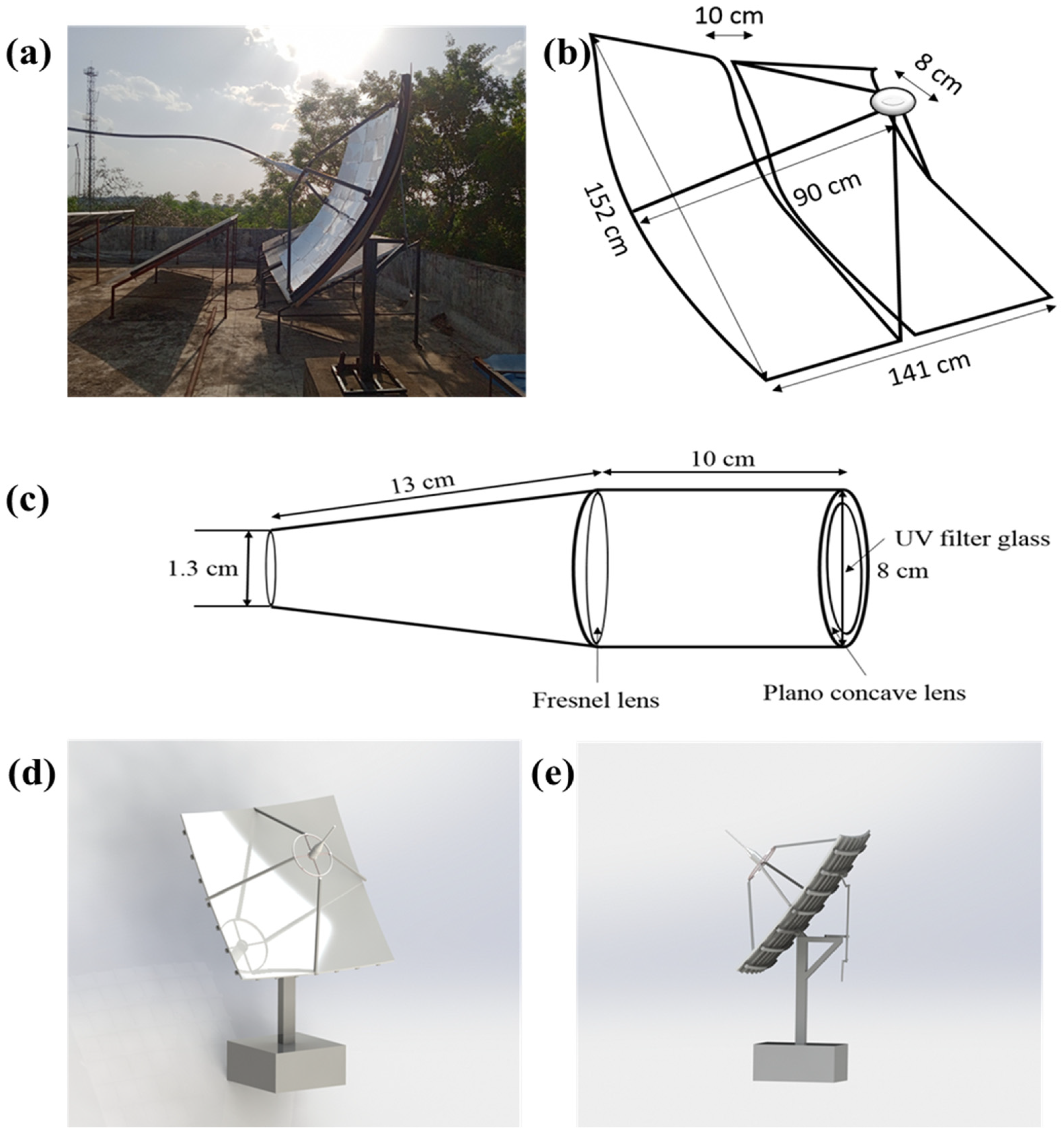
A high-reflectivity parabolic mirror is used to concentrate sunlight onto a focal point. The reflector is designed to capture and focus as much sunlight as possible throughout the day. The operational principle of the system involves the utilization of solar radiation, which is captured by the parabolic dish surface and concentrated, then reflected onto the focal area. Subsequently, the concentrated sunlight is transmitted through a fiber optic bundle (FOB) to convey it to the designated destination as shown in Figure 1a. The primary component of the system is the parabolic solar concentrator area, comprising polyester film. This high-quality aluminum-paint-coated film increases the intensity and spreads light more evenly with a high specular reflectivity index of 95%, illustrated in Figure 1d.
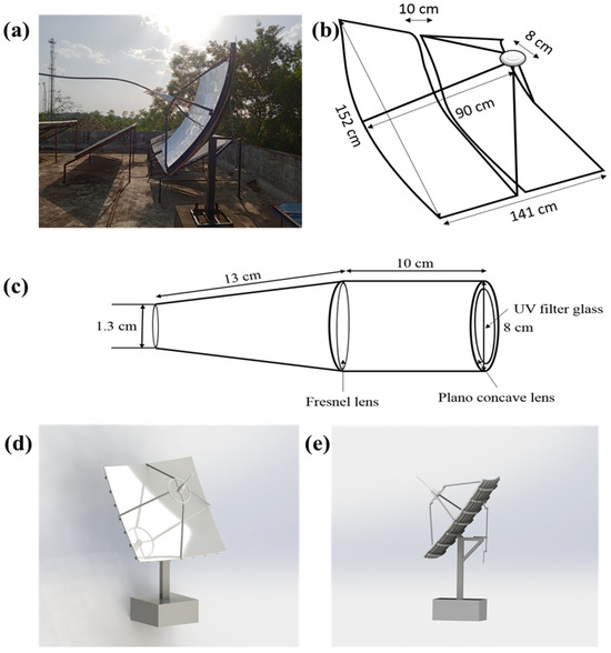
Figure 1.
(a) Installed solar daylighting system on the roof of an energy center. (b) Dimensions of the installed apparatus. (c) Receiver cavity. (d,e) Three-dimensional drawings of the design.
2.2. Plastic Optical Fibers (POFs)
Low-cost POFs are selected for their flexibility and cost-effectiveness. However, their susceptibility to heat damage necessitates careful design considerations to mitigate this issue. To achieve the objective of providing uniform illumination deep within the building at a low cost, the utilization of plastic optical fibers (POFs) emerges as one of the most viable solutions, ensuring cost-effectiveness. A bundle of Polymethyl Methacrylate fiber optic wires (PMMA) was utilized, comprising 60 pieces of 1 mm fibers positioned at the center of the bundle, surrounded by 60 pieces of 1 mm fibers. The mathematical relationship between the energy at the inlet of the fiber optic bundle (Qin) (Equation (1)) and the energy at the end of the bundle (Qout) (Equation (2)) is described by the following equations [25,26].
Assuming that the focal distance is F. The polyester film’s reflection index is . The radiation of the normal beam is Gb. is the parabolic dish’s rim angle, and dBloss is attenuation. Apart from their cost-effectiveness, PMMA fibers also provide the advantage of flexibility within the building environment.
2.3. Mechanical Support for Heat Filtration
Initially, the innovative mechanical support was devised to solely bear the weight of the fiber bundle and maintain its position on the focal surface during solar tracking. This support mechanism was primarily constructed with a single level of filtration, featuring a housing for an optical filter (refer to Figure 1d,e). The Figure 1 depict the industrial design and actual implementation of the innovative mechanical component. An extended hot mirror was employed within the filter to mitigate heat within the optical system without compromising its visible output. Despite the implementation of this filter, which extends the reflection range to approximately 1750 nm, the operational experience revealed that prolonged system usage still led to temperature-induced damage to the optical fiber. To address this issue, we enhanced the mechanical component by incorporating additional filtration levels. We introduced a new filtration combination where two lenses and one glass are used for heat reduction.
2.4. Heat Filtration Mechanism
The heat filtration mechanism consists of three layers of filters designed to reduce the thermal load on the POFs. The three components are UV filter glass, plano-concave lens, and Fresnel lens. A newly patented mechanical component is integrated at the focal point to secure the fiber optic bundle and provide three levels of heat filtration. This component is crucial for protecting the POFs from overheating while maintaining high optical transmission efficiency.
Primary Heat Filter: This layer is composed of a UV-absorbing material that blocks a significant portion of ultraviolet radiation, which contributes to the degradation of POFs. UV filter glass for daylighting functions by selectively blocking ultraviolet (UV) radiation while allowing visible light to pass through. This filtration process helps reduce UV-induced glare and heat, creating a more comfortable and visually appealing indoor environment. By minimizing UV penetration, the filter helps protect interior furnishings and occupants from UV-related damage and health risks. Additionally, it maintains the natural color balance of daylight, enhancing the quality of interior illumination.
Secondary Heat Filter: A plano-concave lens for daylighting works by diverging incoming light rays and spreading them out across a wider area. Made from a heat-resistant polymer, this layer further reduces infrared radiation, preventing excessive heat from reaching the POFs. This lens design helps to evenly distribute natural daylight, reducing glare and shadows in indoor spaces. By dispersing light, it enhances overall illumination levels while maintaining uniformity. Placed strategically in daylighting systems, such lenses optimize the utilization of natural light, promoting energy efficiency in buildings.
Tertiary Heat Filter: The final layer consists of a reflective lens that deflects any remaining heat while allowing visible light to pass through efficiently. A Fresnel lens for daylighting functions by refracting incoming light, focusing it toward a specific area or direction. Its unique design features concentric grooves that bend light, concentrating it onto a focal point. This lens efficiently captures and redirects natural daylight, maximizing its intensity within a space. By concentrating sunlight, it enhances interior illumination levels, reducing the need for artificial lighting. Installed in daylighting systems, Fresnel lenses help optimize energy usage in buildings while providing ample natural light for occupants.
Additionally, we strategically created a calculated space between the filters to facilitate natural ventilation within the system.
As the direct beam from the concentrator converges on the focal point (refer to Figure 1c), it encounters the first UV filter that selectively blocks ultraviolet (UV) radiation while allowing visible light to pass through, and maximum heat should be reduced. After passing through this initial filtration, the beam traverses through a plano-concave lens which evenly distributes natural daylight in a chamber after the vacuum chamber for natural heat ventilation induced by rays, constituting the second level of heat reduction. Subsequently, the light beam encountered through a Fresnel lens refracts incoming light, focusing it toward a specific direction. Finally, the beam enters the fiber optic inlet, transmitting light to the terminal via the light fiber. This refined approach ensures uniform light distribution across each optical fiber, leading to improved efficiency in terms of illumination.
3. Materials and Methods
This study investigated the performance of a novel fiber optic daylighting system designed for efficient light transmission and heat filtration.
3.1. Experimental Setup
The system utilizes a parabolic collector to concentrate sunlight and a newly developed mechanical component to secure the fiber optic bundle at the focal point. For the manually adjustable tracking system utilized in the experiment, a one-axis system was employed. A parabolic collector with a specific focal length was fabricated using the material specification, e.g., a reflective aluminum sheet. The dimensions and surface properties of the collector were optimized for efficient light capture based on reference design. Plastic optical fibers (POFs) were chosen for their cost-effectiveness and light transmission properties. The newly developed mechanical component, designed to secure the fiber optic bundle at the focal point, incorporates three levels of heat filtration. The complete daylighting system, including the parabolic collector, fiber optic bundle with the securing component, and light diffuser (optional), was assembled. The system was positioned outdoors under direct sunlight with the collector facing south (or appropriate direction based on location).
3.2. Instrumentation and Testing
The system’s performance was evaluated through a series of experiments designed to measure the illumination levels and temperature at various points within the system. Measurements were taken at different times of the day to assess the system’s performance under varying sunlight conditions. The experiment was conducted between 1 March 2023 and 31 May 2023. The data for each month represent the conditions on the first day of the month. On 1 March, in the morning, Bhopal experienced essentially clear sky conditions, which became partly cloudy around 10 a.m., followed by a return to clear skies. The average temperature that day was 25 °C, with a wind speed of 6 km/h. On 1 April 2023, there were clear sky conditions throughout the day, with an average temperature of 29 °C and a wind speed of 5 km/h. On 1 May 2023, there were scattered clouds initially, followed by partly cloudy conditions later in the day. The average temperature was 23 °C, with a wind speed of 8 km/h. Illuminance measurements were taken at various distances within the building using a lux meter with multiple data points to assess light distribution and uniformity. It is worth noting that the results encompass both direct lighting and inter-reflection within the measurement environment. The room dimensions, including the height, are as follows: 2.5 m × 2.2 m × 3.2 m. Lux meters were placed at different locations within the building to measure the intensity and uniformity of the distributed light. The uniformity of illumination was calculated using standard metrics like uniformity ratio (U0) or coefficient of variation (CV). An infrared thermometer was used to measure the temperature at different points within the system, including the parabolic collector, securing component, and emerging light from the fiber optic bundle. The experimental setup is illustrated in Figure S1 of the supporting information. Infrared thermometer data were used to assess the effectiveness of the heat filtration mechanism in reducing heat transfer through the fiber optic bundle. Infrared thermometers were used to monitor the temperature of the POFs and other critical components. These measurements helped assess the effectiveness of the heat filtration mechanism in protecting the POFs from overheating. The temperature measurements were compared with the ambient temperature to determine the system’s thermal performance.
3.3. Simulation with RELUX Software
RELUX simulation software was used to model the daylighting system and its light distribution characteristics. The simulated illumination map was compared with the experimental data to verify the performance of the system and the accuracy of the design. To verify and complement the experimental results, the system was modeled and simulated using RELUX, a lighting simulation software (version 2019.1) program. The physical dimensions and reflective properties of the parabolic reflector, the optical characteristics of the POFs, and the heat filtration mechanism were modeled in RELUX. Simulations were run under various lighting conditions, including different sun angles and intensities, to predict the system’s performance in real-world scenarios. The simulated illumination levels and temperature profiles were compared with the experimental data to validate the accuracy and reliability of the simulation model.
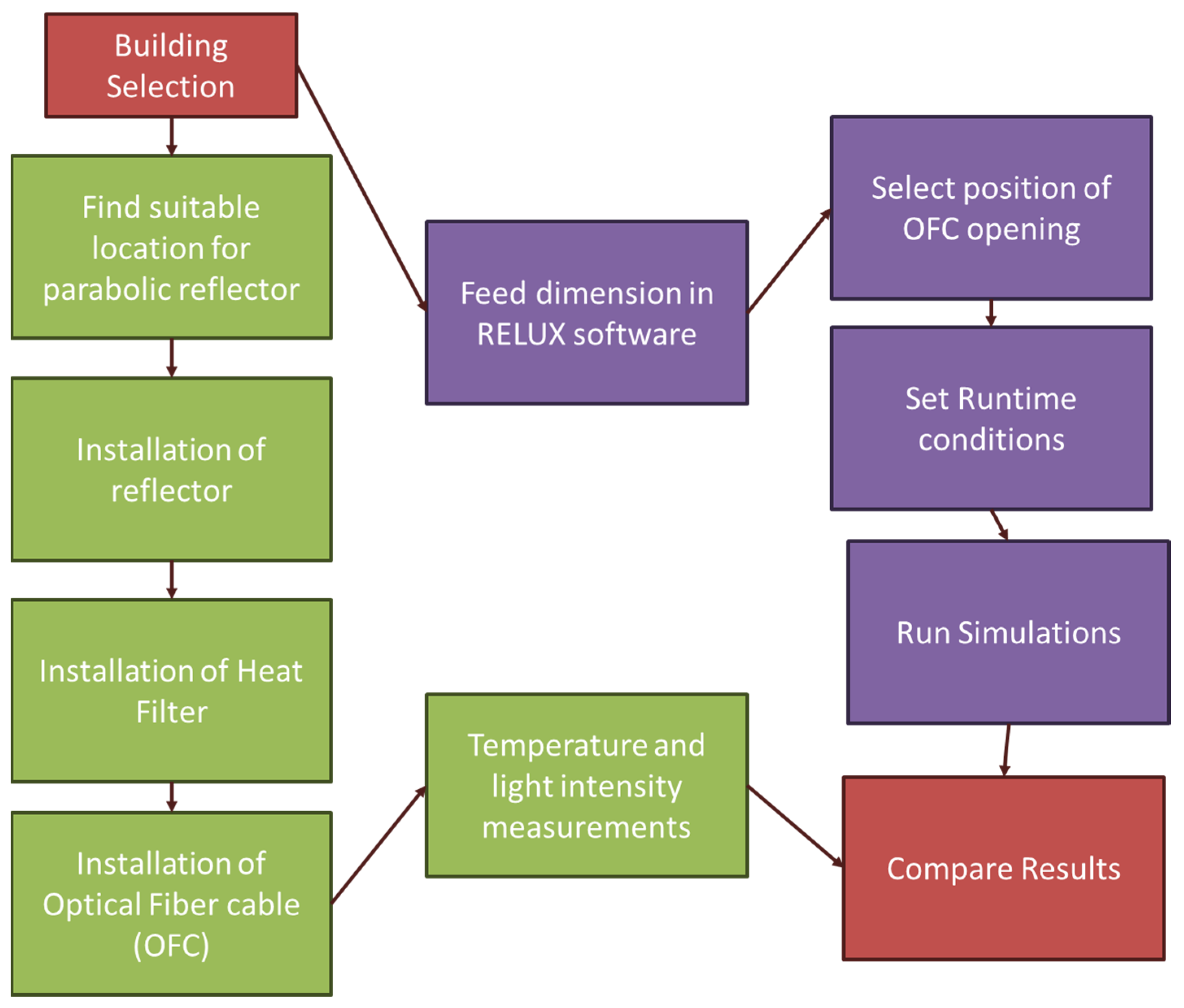
Figure 2 shows the flow chart detailing the design and implementation of the research methodology. This chart provides a comprehensive overview of the sequential steps and processes involved in our study. It illustrates the various stages of the research, from initial planning and experimental setup to data collection and analysis. The flow chart also highlights the key components and their interrelationships, offering a visual representation of how each step integrates into the overall research framework. This aims to enhance understanding and facilitate replication of our methodology by clearly mapping out the entire research process.
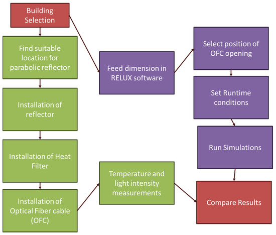
Figure 2.
Flow chart of research methodology.
4. Results
4.1. Temperature Control
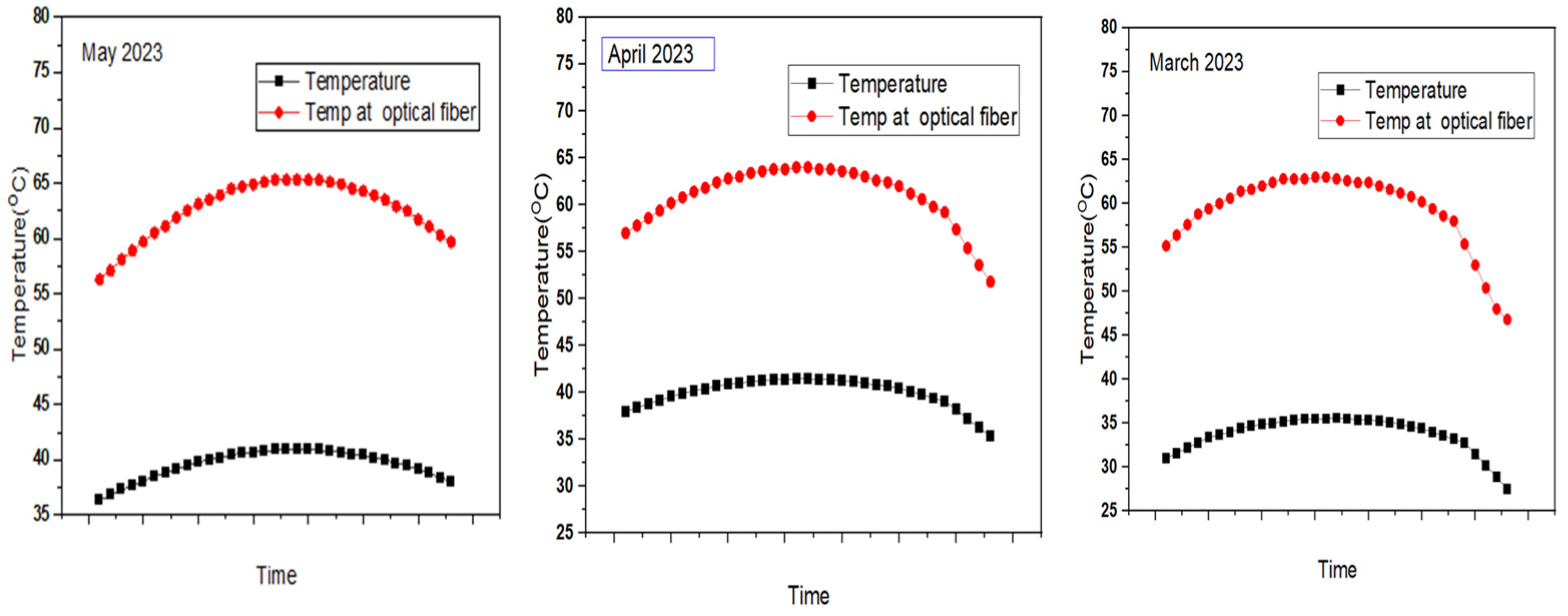
The infrared thermometer readings demonstrated that the heat filtration mechanism effectively reduced the temperature of the POFs. The maximum recorded temperature of the POFs was consistently below 40 °C, well within the safe operating range for these materials. Figure 3 depicting the temperature difference between ambient conditions and the input of the optical fiber after installing the component showcases a remarkable reduction in temperature, particularly evident during May, March, and April. The multi-layer heat filtration system was particularly effective in reducing the thermal load. The primary filter reduced UV radiation by approximately 70%, while the secondary and tertiary filters collectively reduced infrared radiation by an additional 50%. This substantial decrease, averaging around 35 degrees Celsius, signifies an exceptional improvement in heat management within the system.
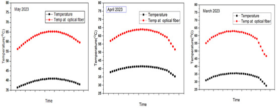
Figure 3.
Temperature comparison of ambient vs. internal at optical fiber for different months.
Such a significant reduction in temperature can be attributed to the effectiveness of the installed component in mitigating heat transfer to the optical fiber. Overall, the substantial decrease in temperature observed highlights the effectiveness of the installed component in managing heat within the optical fiber system. By implementing measures to reduce heat transfer and enhance thermal management, the component successfully maintains lower temperatures at the fiber input, ensuring optimal performance and longevity of the optical fiber in various environmental conditions.
4.2. Optimum Illumination Distribution
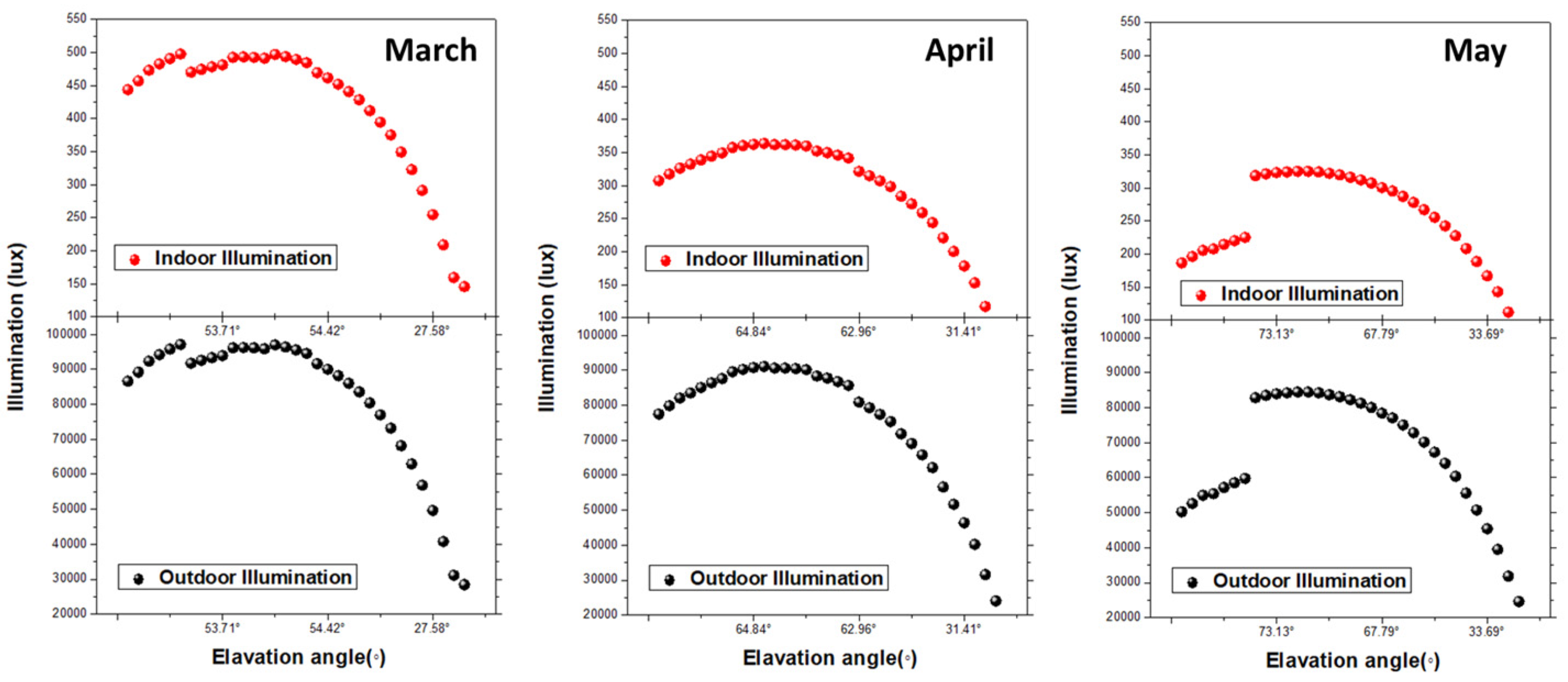
The effectiveness of the component in carrying illumination from outdoor ambient conditions to indoor spaces is crucial for evaluating its performance. The distribution of light was found to be highly uniform, with a standard deviation of less than 10% across the measured points. This uniformity is critical for maintaining consistent lighting conditions throughout the day. The lux meter readings indicated that the system achieved high levels of illumination deep within the building. The measured illuminance varied between 500 lux to 350 lux at peak sunlight hours, ensuring sufficient lighting for typical indoor activities. Figure 4 showcases the difference in outdoor and indoor illumination levels providing valuable insight into the component’s efficacy. The availability of approximately 400–450 lux of illumination indoors, as measured using the setup, indicates a significant success in achieving the desired outcome.
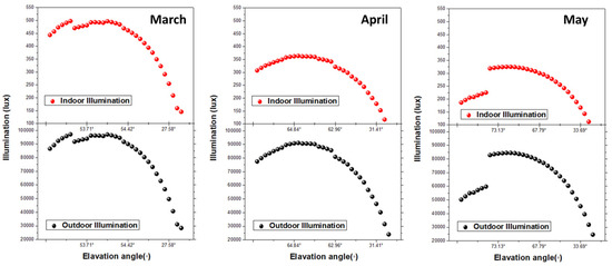
Figure 4.
Illumination comparison ambient vs. indoor at optical fiber for different months.
Achieving indoor illumination levels of 400–450 lux using the setup demonstrates the high effectiveness of the component in carrying illumination from outdoor ambient conditions to indoor spaces. This success not only enhances visual comfort and productivity but also promotes energy efficiency and occupant well-being, highlighting the significant benefits of utilizing natural light in indoor environments. The ability to achieve 400–450 lux of indoor illumination demonstrates effective daylighting, where natural light is harnessed to illuminate indoor environments. This is particularly important for reducing reliance on artificial lighting sources during daylight hours, leading to energy savings and environmental benefits. Adequate indoor illumination levels contribute to improved visual comfort and productivity for occupants. By providing sufficient natural light, the component enhances the overall indoor environment, creating a more pleasant and conducive atmosphere for various activities. The ability of the component to deliver substantial indoor illumination levels ensures that occupants can reap these health-related advantages. By reducing the need for artificial lighting, the effective transmission of natural light indoors results in cost savings associated with energy consumption.
4.3. Simulation Results
Additionally, as a proof of concept, simulations using Relux software were carried out to demonstrate the effectiveness of the setup. The RELUX simulations closely matched the experimental results, with predicted illuminance levels within 5% of the measured values. This high level of accuracy confirms the reliability of the simulation model in predicting the system’s performance. The temperature profiles obtained from the simulation were also in good agreement with the experimental data, further validating the effectiveness of the heat filtration mechanism.
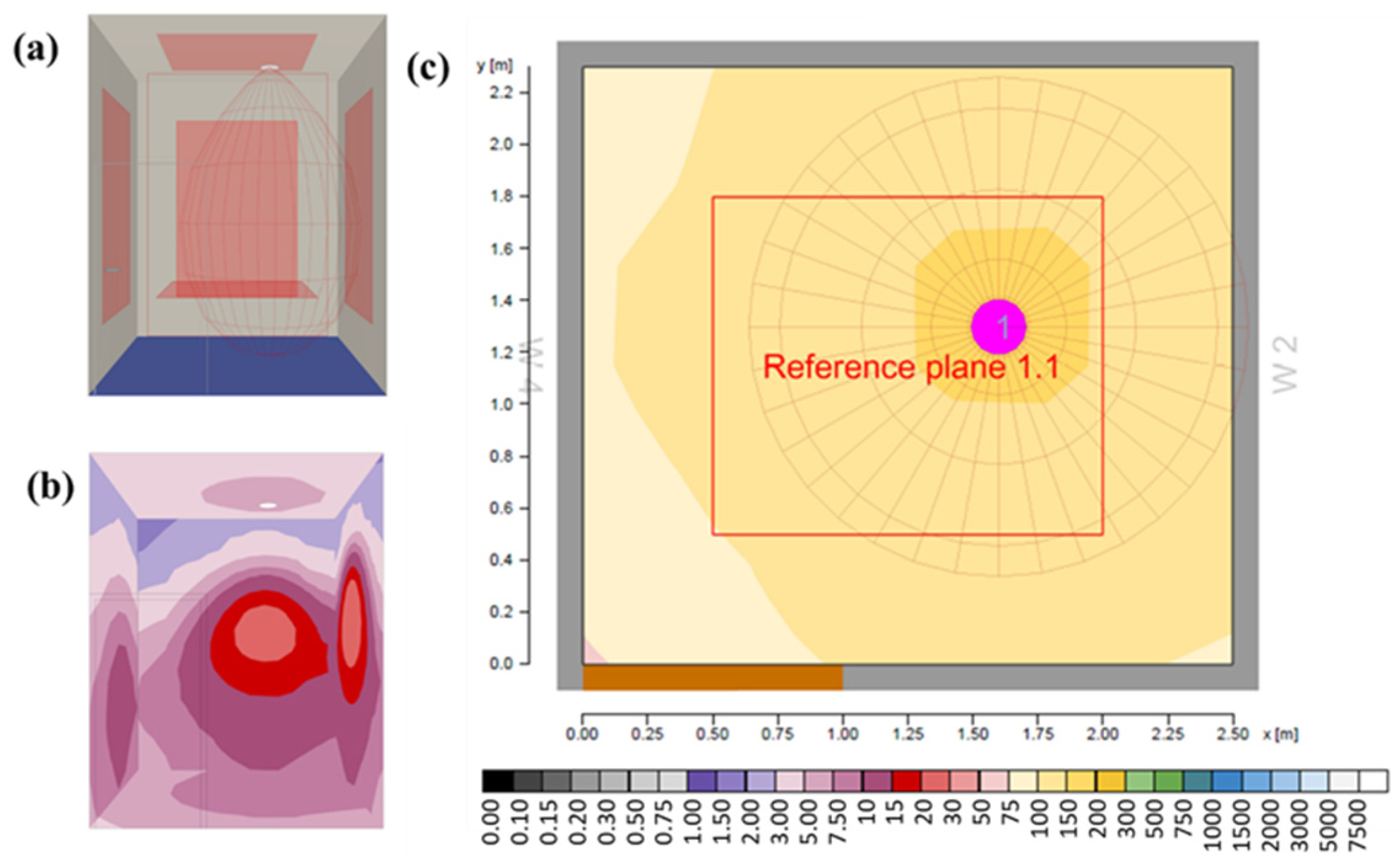
Figure 5a is the 3D model that showcases a demo room meticulously designed to serve as a controlled environment for simulating various light sources. Its purpose revolves around studying the behavior and impact of different lighting conditions, encompassing natural sunlight. The design emphasizes flexibility and precision, featuring adjustable walls, ceilings, and floors to modify the space’s dimensions, while surfaces and materials are chosen for their reflective properties. The room houses sophisticated simulation equipment to accurately reproduce diverse lighting scenarios, enabling researchers and designers to analyze the effects of illumination on spaces, objects, and human perception. Figure 5b shows the pseudo-color model depicting light distribution in the room illustrating a uniform spread of illumination across its entirety. Through meticulous calibration and analysis, this model accurately represents the consistent distribution of light intensity, showcasing minimal variation or discrepancies throughout the space. Each color gradient corresponds to specific light intensity levels, with a cohesive and balanced spectrum pervading the room. This further asserts the usefulness of the proposed system. The pseudo-reference plane depicted in the 2D cross-sectional representation Figure 5b illustrates a comprehensive view of light distribution within space. This visual tool effectively demonstrates the consistency and evenness of light intensity across different planes within the room. By showcasing how light propagates and spreads through the environment, it offers crucial insights into the efficacy of the new lighting system. The uniformity and balance observed in the distribution of light along the reference plane confirm the effectiveness of the system in achieving its intended objective of providing consistent illumination throughout the designated area. This validation supports the system’s suitability for various applications, affirming its capability to meet lighting requirements with precision and reliability.
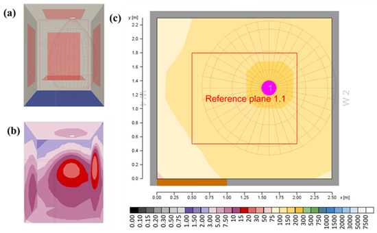
Figure 5.
Simulation results: (a) 3D view of the demo room, (b) pseudo-color model showing light distribution (lux), and (c) pseudo-reference plane.
4.4. Discussion
The primary objective of optical fibers is indeed to transfer light efficiently, rather than heat. Optical fibers are specifically designed to guide and transmit light signals over long distances with minimal loss and distortion. However, it is essential to acknowledge that in practical applications, optical fibers can still be subjected to heat due to various factors, including environmental conditions, nearby heat sources, and the intensity of light they are transmitting. While the focus is on light transmission, heat management remains crucial for ensuring the optimal performance and longevity of optical fibers. Excessive heat can degrade the optical properties of the fiber, leading to signal attenuation, increased signal noise, and even physical damage in extreme cases. Effective heat management is essential to ensure their reliable operation and longevity. By minimizing heat-related effects, optical fibers can maintain their efficiency and integrity, providing reliable transmission of light signals over extended periods. In this study, the addition of a heat filtration device resulted in a significant reduction in the temperature input to the optical fiber. This improvement can be scientifically explained by considering the following factors:
The heat filtration device may act as a heat sink, absorbing and dissipating heat away from the optical fiber. When optical fiber is exposed to sunlight, it absorbs radiant energy, leading to an increase in temperature. By introducing a heat sink, the excess heat is transferred away from the fiber, reducing its temperature. The filtration device may also provide thermal insulation, creating a barrier between the optical fiber and external heat sources. This insulation prevents the direct transfer of heat to the fiber, thereby reducing its temperature. The design of the filtration device may incorporate features that increase its surface area. A larger surface area facilitates better heat dissipation, allowing more efficient cooling of the optical fiber. The choice of materials for the filtration device is crucial in determining its thermal conductivity and heat dissipation capabilities. Materials with high thermal conductivity, such as metals or heat-conductive polymers, are effective in rapidly transferring heat away from the optical fiber. High temperatures can cause thermal degradation of the fiber’s materials, leading to changes in its optical properties. For example, prolonged exposure to heat can cause the fiber’s core and cladding materials to expand or contract, altering the refractive index and affecting light transmission. The precise positioning of the filtration device relative to the optical fiber is essential for optimal heat reduction. Placing the part near the fiber ensures efficient heat transfer and minimizes temperature buildup.
The overall cost of the project was USD 281.75 with the heat filtration device accounting for USD 15.49 of that total (Table 1). When calculated as a percentage, the cost of the heat filtration device represents 5.5% of the entire project expenditure. This indicates that a small portion of the project’s budget was allocated to the heat filtration device, highlighting its relative cost-effectiveness within the broader scope of the project.

Table 1.
Cost analysis of the system.
Overall, the introduction of a heat filtration device serves to enhance the thermal management of the optical fiber within the solar daylighting system. By effectively dissipating heat and providing insulation, this component contributes to maintaining lower temperatures, thereby improving the performance and longevity of the fiber.
5. Conclusions
The combined experimental and simulation results highlight the system’s potential to provide efficient and uniform daylighting while mitigating the risk of POF overheating. The design demonstrated its ability to effectively manage heat, improve light transmission, and offer numerous benefits to indoor environments, a significant advancement in enhancing its efficacy and overall performance. Firstly, the component’s capability to mitigate heat transfer to the optical fiber contributes to the system’s efficiency and longevity. By reducing the temperature input to the fiber, potential heat-related damage is minimized, ensuring prolonged operational life and durability of the optical fiber. Secondly, the improved light transmission achieved with the component leads to enhanced indoor illumination levels. This not only promotes visual comfort and productivity but also reduces reliance on artificial lighting sources, resulting in energy savings and environmental sustainability. Furthermore, the component’s ability to reduce indoor temperatures underscores its role in contributing to thermal comfort within indoor spaces. By effectively managing heat, occupants can enjoy a more comfortable environment, particularly during periods of intense sunlight and high temperatures.
Overall, the addition of the filtration device component to the optical fiber daylighting system represents a holistic approach to optimizing the optical fiber daylighting system. As we continue to explore innovative solutions for sustainable lighting and environmental comfort, the integration of such components underscores our commitment to creating healthier, more efficient indoor spaces for the well-being of occupants and the planet alike. Although the three levels of heat filtration reduce the lighting efficiency, the guidelines of the minimum requirement of light for a living area require around 300 to 500 lux. The setup can efficiently deliver an average light in the daytime of around 400 lux which is well within acceptable limits. This is useful for basements or other areas where daylight cannot reach through windows. The filtration device helps in employing optical fibers with lower temperature ratings. These findings suggest that the proposed parabolic solar daylighting system, with its innovative heat filtration mechanism, is a viable solution for sustainable and efficient daylighting in modern buildings
Future scope: Recommendations for future research include exploring advanced materials for even more effective heat filtration and optimizing the geometry of the parabolic reflector to enhance light concentration and distribution. The relationship between the distance from the light source and the illuminance level can be analyzed to understand the light attenuation characteristics of the fiber optic bundle. The impact of different heat filtration levels on light transmission efficiency can be investigated by comparing the performance with and without specific filtration components. The optimal balance between heat dissipation and lighting effects can be explored. This includes investigating advanced heat filtration techniques that enable maximum light transmission while preserving the integrity of the optical fibers. By optimizing this balance, the system’s efficiency could be improved, allowing for broader applications in areas where both high-intensity lighting and effective thermal management are essential. Further research and development could lead to widespread adoption of this technology, significantly reducing the energy consumption and environmental impact of artificial lighting.
Supplementary Materials
The following supporting information can be downloaded at: https://www.mdpi.com/article/10.3390/eng5040140/s1, Figure S1: Experimental set-up of the system; Table S1: Cost analysis of the system. Figure S2: Flow chart of research methodology.
Author Contributions
Conceptualization, A.S. and S.K.; methodology, E.C.; software, L.U.; validation, L.U., A.S. and S.K.; formal analysis, E.C.; investigation, A.S.; resources, L.U.; data curation, L.U.; writing—original draft preparation, A.S.; writing—review and editing, E.C.; visualization, S.K.; supervision, A.S.; project administration, E.C.; funding acquisition, S.K. All authors have read and agreed to the published version of the manuscript.
Funding
This research received no external funding.
Institutional Review Board Statement
Not applicable.
Informed Consent Statement
Not applicable.
Data Availability Statement
No new data were created or developed. The original contributions presented in the study are included in the article, further inquiries can be directed to the corresponding authors.
Acknowledgments
The technical support of MANIT-Bhopal, India, and Universiti Malaysia Pahang Al Sultan Abdullah (www.umpsa.edu.my, accessed on 12 April 2024) is greatly acknowledged. We are also thankful to our Alumni student Vipin Vipinraj Sugathan, Nanyang Technological University Singapore for his assistance.
Conflicts of Interest
The authors declare no conflicts of interest.
References
- Yi, R.; Shao, L.; Su, Y.; Riffat, S. Daylighting performance of atriums in subtropical climate. Int. J. Low-Carbon Technol. 2009, 4, 230–237. [Google Scholar] [CrossRef]
- Krarti, M.; Erickson, P.M.; Hillman, T.C. A simplified method to estimate energy savings of artificial lighting use from daylighting. Build. Environ. 2005, 40, 747–754. [Google Scholar] [CrossRef]
- Li, D.H.; Wong, S. Daylighting and energy implications due to shading effects from nearby buildings. Appl. Energy 2007, 84, 1199–1209. [Google Scholar] [CrossRef]
- Barton, J.; Thomson, M.; Sandwell, P.; Mellor, A. A Domestic Demand Model for India. In Advances in Energy Research; Springer: Singapore, 2020; pp. 743–753. [Google Scholar] [CrossRef]
- The Official Website of Ministry of Environment, Forest and Climate Change, Government of India. Available online: http://www.moef.nic.in/en/downloads/public-information/Residentialpowe (accessed on 11 April 2022).
- Rubab, S.; Kandpal, T.C. Resource-Technology Combinations for Domestic Lighting in Rural India: A Comparative Financial Evaluation. Energy Sources 1997, 19, 813–831. [Google Scholar] [CrossRef]
- Bahadiroğlu, A.; Koç, A.Y.; Parlak, E.; Larsson, N.; Kujawski, W.; Unver, U. Sustainable building evaluation: A case study. Energy Sources Part A Recover. Util. Environ. Eff. 2022, 44, 3149–3163. [Google Scholar] [CrossRef]
- Tabrizi, A.; Sanguinetti, P. Life-cycle cost assessment and energy performance evaluation of NZEB enhancement for LEED-rated educational facilities. Adv. Build. Energy Res. 2015, 9, 267–279. [Google Scholar] [CrossRef]
- Terrill, T.J.; Bay, C.J.; Rasmussen, B.P. Autonomous lighting assessments in buildings: Part 2—Light identification and energy analysis. Adv. Build. Energy Res. 2016, 11, 227–244. [Google Scholar] [CrossRef]
- Ihm, P.; Nemri, A.; Krarti, M. Estimation of lighting energy savings from daylighting. Build. Environ. 2009, 44, 509–514. [Google Scholar] [CrossRef]
- A Critical Review of Simulation Techniques for Daylight Responsive Systems|L Doulos—Academia.edu. Available online: https://www.academia.edu/25457051/A_critical_review_of_simulation_techniques_for_daylight_responsive_systems (accessed on 11 April 2022).
- Udhwani, L.; Soni, A. Evaluation of daylighting performance in an office building: A case study. Mater. Today Proc. 2021, 46, 5626–5631. [Google Scholar] [CrossRef]
- Sayigh, A. Sustainability, Energy and Architecture Case Studies in Realizing Green Buildings. 2014. Available online: http://wrenuk.co.uk (accessed on 11 April 2022).
- Ghisi, E.; Tinker, J.A. Evaluating the potential for energy savings on lighting by integrating fibre optics in buildings. Build. Environ. 2006, 41, 1611–1621. [Google Scholar] [CrossRef]
- Doulos, L.; Tsangrassoulis, A.; Topalis, F. Quantifying energy savings in daylight responsive systems: The role of dimming electronic ballasts. Energy Build. 2008, 40, 36–50. [Google Scholar] [CrossRef]
- Kurian, C.; Aithal, R.; Bhat, J.; George, V. Robust control and optimisation of energy consumption in daylight—Artificial light integrated schemes. Light. Res. Technol. 2008, 40, 7–24. [Google Scholar] [CrossRef]
- Loutzenhiser, P.G.; Maxwell, G.M.; Manz, H. An empirical validation of the daylighting algorithms and associated interactions in building energy simulation programs using various shading devices and windows. Energy 2007, 32, 1855–1870. [Google Scholar] [CrossRef]
- Liu, G.; Liu, H. Using Insulation in China’s Buildings: Potential for Significant Energy Savings and Carbon Emission Reductions. Low Carbon Econ. 2011, 02, 220–223. [Google Scholar] [CrossRef][Green Version]
- Rosen, M.A. Net-Zero Energy Buildings and Communities: Potential and the Role of Energy Storage. J. Power Energy Eng. 2015, 03, 470–474. [Google Scholar] [CrossRef]
- Öztürk, L.D. Determination of Energy Losses in Lighting in Terms of Good Vision Efficiency. Arch. Sci. Rev. 2008, 51, 39–47. [Google Scholar] [CrossRef]
- Shankar, A.; Krishnasamy, V.; Babu, B.C. Smart LED lighting system with occupants’ preference and daylight harvesting in office buildings. Energy Sources Part A Recover. Util. Environ. Eff. 2020, 18, 1–21. [Google Scholar] [CrossRef]
- Akrasakis, S.; Tsikalakis, A.G. Corridor lighting retrofit based on occupancy and daylight sensors: Implementation and energy savings compared to LED lighting. Adv. Build. Energy Res. 2018, 12, 274–288. [Google Scholar] [CrossRef]
- Mayhoub, M.S. Innovative Daylighting Systems’ Challenges: A Critical Study. Energy Build. 2014, 80, 394–405. Available online: https://www.sciencedirect.com/science/article/pii/S0378778814003193 (accessed on 20 April 2024). [CrossRef]
- Chadichal, S.S.; Misra, S.; Vashishta, D.S. Circular Model/Economy and Sustainability Strategies for Long-Term Prosperity for a Retail Sector in India: A Study on Clothing Consumerism. May 2022. Available online: http://gnanaganga.inflibnet.ac.in:8080/jspui/handle/123456789/573 (accessed on 20 April 2024).
- Ullah, I.; Shin, S.-Y. Development of optical fiber-based daylighting system with uniform illumination. J. Opt. Soc. Korea 2012, 16, 247–255. Available online: https://opg.optica.org/abstract.cfm?uri=josk-16-3-247 (accessed on 20 April 2024). [CrossRef]
- Ullah, I.; Whang, A.J.-W. Development of Optical Fiber-Based Daylighting System and Its Comparison. Energies 2015, 8, 7185–7201. [Google Scholar] [CrossRef]
- Ullah, I.; Shin, S. Uniformly Illuminated Efficient Daylighting System. Smart Grid Renew. Energy 2013, 04, 161–166. [Google Scholar] [CrossRef]
- Kandilli, C.; Ulgen, K. Review and modelling the systems of transmission concentrated solar energy via optical fibres. Renew. Sustain. Energy Rev. 2007, 13, 67–84. [Google Scholar] [CrossRef]
- Kandilli, C.; Ulgen, K.; Hepbasli, A. Exergetic assessment of transmission concentrated solar energy systems via optical fibres for building applications. Energy Build. 2008, 40, 1505–1512. [Google Scholar] [CrossRef]
- He, K.; Zheng, H.; Li, Z.; Taotao; Dai, J. Design and investigation of a novel concentrator used in solar fiber lamp. Sol. Energy 2009, 83, 2086–2091. [Google Scholar] [CrossRef]
- Wang, C.; Abdul-Rahman, H.; Rao, S. Daylighting can be fluorescent: Development of a fiber solar concentrator and test for its indoor illumination. Energy Build. 2009, 42, 717–727. [Google Scholar] [CrossRef]
- Han, H.; Kim, J.T. Application of high-density daylight for indoor illumination. Energy 2010, 35, 2654–2666. Available online: https://www.sciencedirect.com/science/article/pii/S0360544209001935 (accessed on 20 April 2024). [CrossRef]
- Sapia, C. Daylighting in buildings: Developments of sunlight addressing by optical fiber. Sol. Energy 2013, 89, 113–121. [Google Scholar] [CrossRef]
- Xue, X.; Zheng, H.; Su, Y.; Kang, H. Study of a novel sunlight concentrating and optical fibre guiding system. Sol. Energy 2011, 85, 1364–1370. [Google Scholar] [CrossRef]
- Lingfors, D.; Volotinen, T. Illumination performance and energy saving of a solar fiber optic lighting system. Opt. Express 2013, 21, A642–A655. Available online: https://opg.optica.org/abstract.cfm?uri=oe-21-S4-A642 (accessed on 20 April 2024). [CrossRef]
- Reinhart, C.; Fitz, A. Findings from a survey on the current use of daylight simulations in building design. Energy Build. 2006, 38, 824–835. [Google Scholar] [CrossRef]
- Kim, C.-S.; Chung, S.-J. Daylighting simulation as an architectural design process in museums installed with toplights. Build. Environ. 2010, 46, 210–222. [Google Scholar] [CrossRef]
- Ng, E.Y.-Y.; Poh, L.K.; Wei, W.; Nagakura, T. Advanced lighting simulation in architectural design in the tropics. Autom. Constr. 2001, 10, 365–379. [Google Scholar] [CrossRef]
- Li, D.; Lau, C.; Lam, J. Predicting daylight illuminance by computer simulation techniques. Light. Res. Technol. 2004, 36, 113–128. [Google Scholar] [CrossRef]
- Mardaljevic, J. Verification of program accuracy for illuminance modelling: Assumptions, methodology and an examination of conflicting findings. Light. Res. Technol. 2004, 36, 217–239. [Google Scholar] [CrossRef]
- Maamari, F.; Fontoynont, M.; Adra, N. Application of the CIE test cases to assess the accuracy of lighting computer programs. Energy Build. 2006, 38, 869–877. [Google Scholar] [CrossRef]
- Bhavani, R.G.; Khan, M.A. An intelligent simulation model for blind position control in daylighting schemes in buildings. Build. Simul. 2009, 2, 253–262. [Google Scholar] [CrossRef]
- Bhavani, R.; Khan, M. Advanced Lighting Simulation Tools for Daylighting Purpose: Powerful Features and Related Issues. Trends Appl. Sci. Res. 2011, 6, 345–363. [Google Scholar] [CrossRef]
- Bhavani, R.G.; Khan, M.A. Present Trends and Future Direction of Lighting Control in Dubai. In Proceedings of the 4th IEEE GCC Conf 2007, Manama, Kingdom of Bahrain, 11–14 November 2007; pp. 1–5. [Google Scholar]
- Bhavani, R.G.; Khan, M. Prevalence and Penetration of Lighting Control Systems in Dubai Buildings: A Pointer to Future Measures. J. Appl. Sci. 2008, 8, 3460–3466. [Google Scholar] [CrossRef]
Disclaimer/Publisher’s Note: The statements, opinions and data contained in all publications are solely those of the individual author(s) and contributor(s) and not of MDPI and/or the editor(s). MDPI and/or the editor(s) disclaim responsibility for any injury to people or property resulting from any ideas, methods, instructions or products referred to in the content. |
© 2024 by the authors. Licensee MDPI, Basel, Switzerland. This article is an open access article distributed under the terms and conditions of the Creative Commons Attribution (CC BY) license (https://creativecommons.org/licenses/by/4.0/).

