Article

A Novel Planar Power Divider/Combiner for Wideband High-Power Applications

1
Institut National de la Recherche Scientifique (INRS-EMT), University of Quebec, Montreal, QC H5A 1K6, Canada
2
Department of Electrical Engineering, George Washington University (GWU), Washington, DC 20052, USA
*
Author to whom correspondence should be addressed.
Eng 2022, 3(4), 467-475; https://doi.org/10.3390/eng3040033
Submission received: 12 October 2022 / Revised: 10 November 2022 / Accepted: 11 November 2022 / Published: 14 November 2022
(This article belongs to the Section Electrical and Electronic Engineering)

Abstract

:
This manuscript presents a novel wideband power divider with high power handling capability. The power handling capacity of the power divider is increased through the use of grounded 50 ohm loads. The full circuit analysis of a single section of the proposed structure is presented utilizing even and odd modes and ABCD matrices. The final designed sections are cascaded and extended to achieve a high bandwidth response for the target of X-band. The structure was designed and optimized with the method of moments based on ADS software and simulated in HFSS for 3D full-wave analysis. A prototype module was fabricated and measured for experimental validation. The simulation results were confirmed by through measurements for the frequency band of 7–12 GHz (more than 52% fractional bandwidth). A divider such as the proposed one has a significantly higher power handling capacity than Wilkinson, as well as a wider frequency bandwidth than Gysel power dividers. As a wideband high-power power divider, the proposed device is ideal for high-data rate radar or satellite applications.

1. Introduction

Power dividers have many applications in telecommunication systems, such as power amplifiers and array antennas [1,2,3]. The Wilkinson power divider is a popular component in radio frequency and microwave circuits, and it has a critical role in several technologies, systems, and configurations, such as array antenna feeding networks [4,5,6], multi-port technologies/sensors [7,8,9], and non-reciprocal systems [10,11,12]. Dual-band Wilkinson power dividers have been developed using different ways in recent years, along with the introduction of the multiband wireless communication system [13,14,15]. These dual-band Wilkinson power dividers can only be terminated with nominal impedances. Many microwave components, such as transistors, diodes, and antennas, cannot be utilized directly because their input or output ports have a frequency-dependent complex impedance [16]. To accomplish impedance matching, an additional impedance transformer must be placed between Wilkinson power dividers and microwave components. As a result, in practice, broadband Wilkinson dividers require resistors with different values and cannot handle high powers [17].
On the other hand, Gysel power dividers (GPDs) have a higher power handling capability [18]. In comparison with Wilkinson power dividers, Gysel power dividers’ use of grounded resistors is one of their advantages [19]. GPDs can handle more power by using grounded resistors, which transfer heat to the ground. A number of works have been published on Gysel power dividers [20,21,22,23], but these designs have a low ratio of frequency bandwidth. Figure 1 shows the structure of conventional Wilkinson and Gysel Power dividers. To achieve a greater bandwidth, the multi-section model cannot be implemented in GPDs due to their specific structure. So, we are limited to designing a GPD at a central frequency with a fixed bandwidth [18]. To the knowledge of the authors, there has not been any reported paper on the bandwidth enhancement of a GPD.
In this paper, a novel wideband power divider with high power handling capability is proposed. A divider such as the proposed one has a significantly higher power handling capacity than Wilkinson, as well as a wider frequency bandwidth than GPD. With multiple sections stacked together, a wider bandwidth can be achieved at the output ports of the final structure. The multi-section Wilkinson configuration requires several resistors with different values [24], whereas the proposed multi-section power divider requires only grounded resistors for isolation purposes, and the resistor’s value is equivalent to the design’s characteristic impedance.
In order to understand the theory of the proposed power divider, the circuit analysis of a single section has been provided. The designed power divider is operating over the entire X-band frequency (i.e., 7–12 GHz). For verification, a prototype of the HFSS-modeled design was implemented and measured with a vector network analyzer (VNA). As reported herein, the simulation and measurement results were found to be in excellent agreement.

2. Materials and Methods

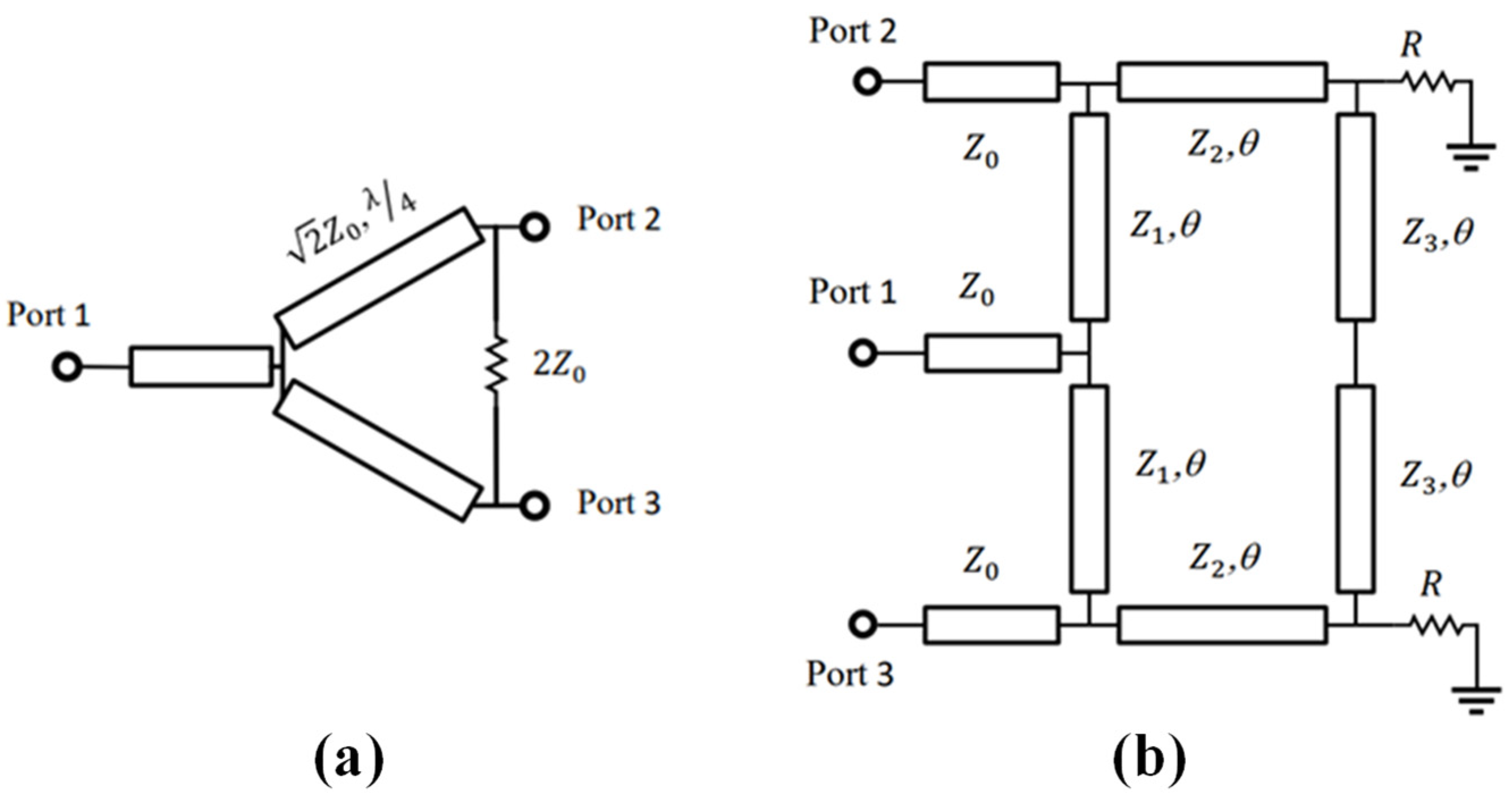
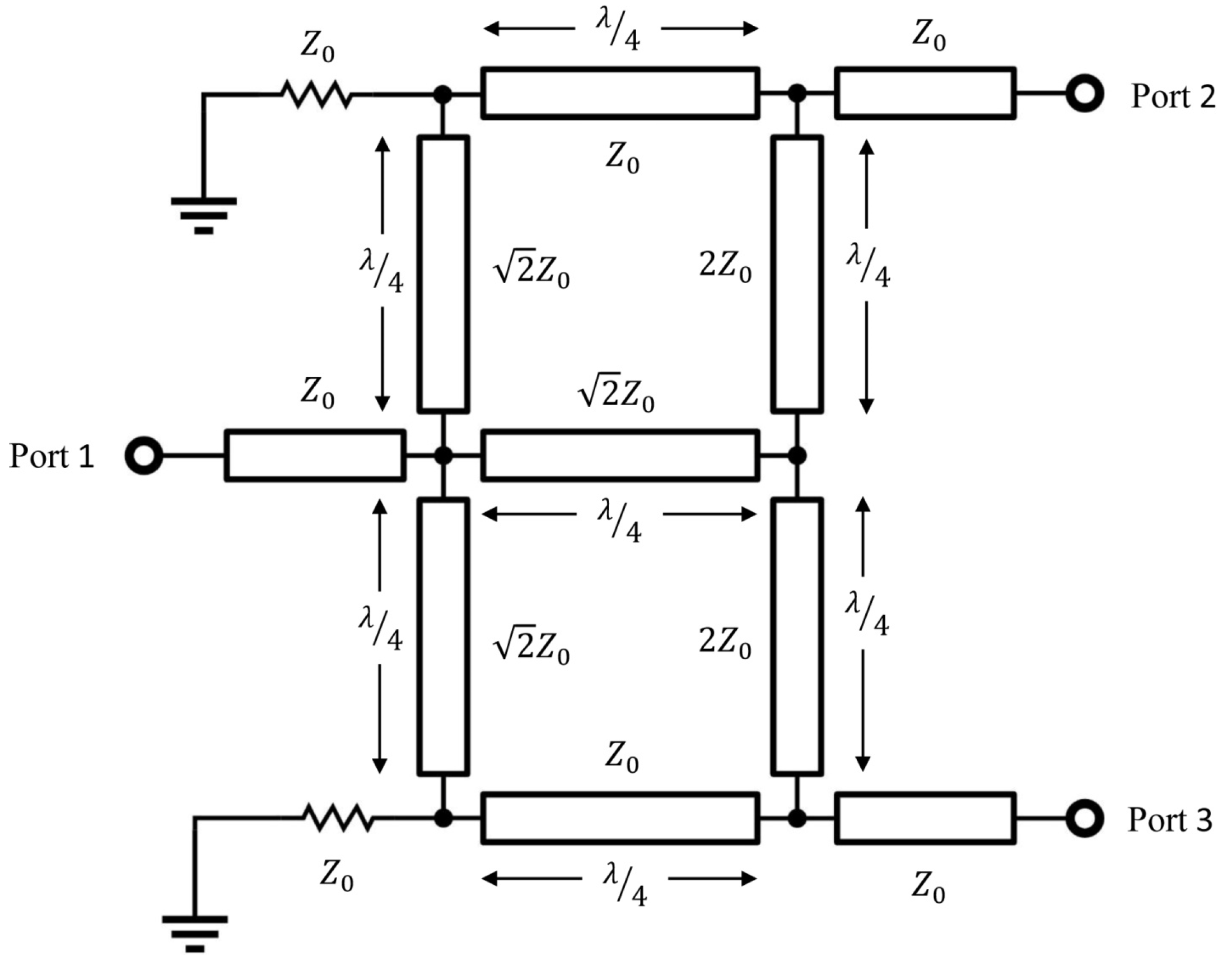
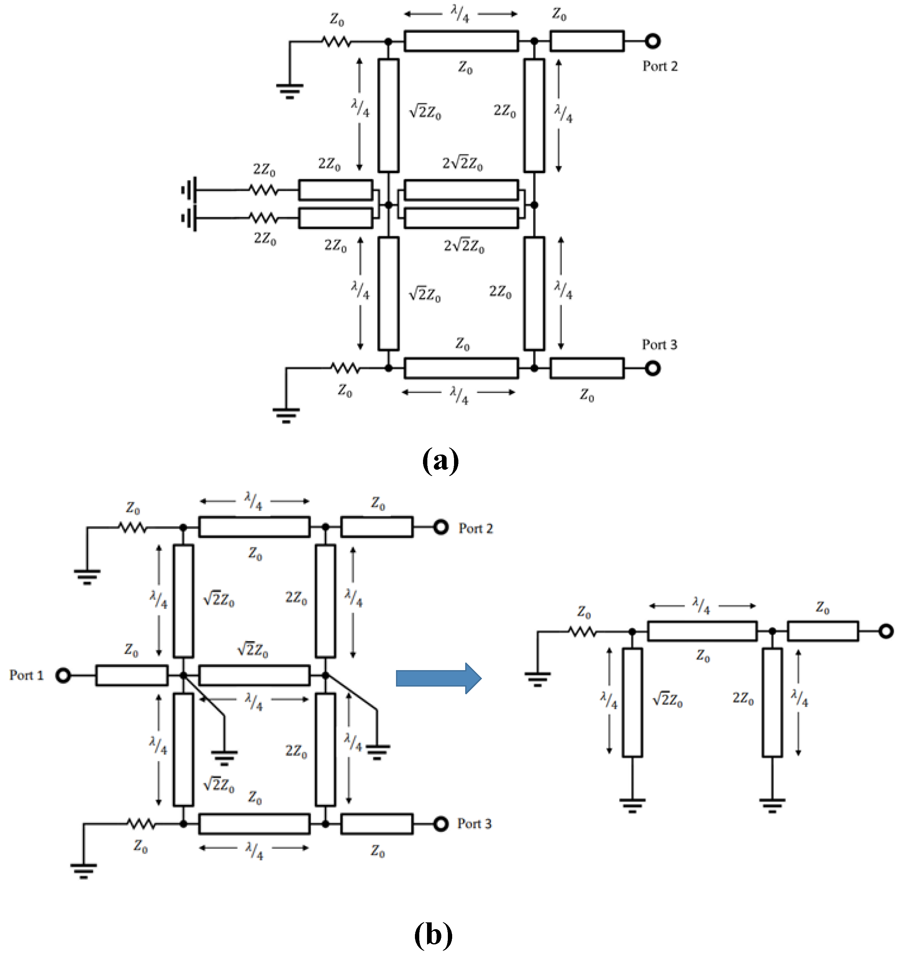
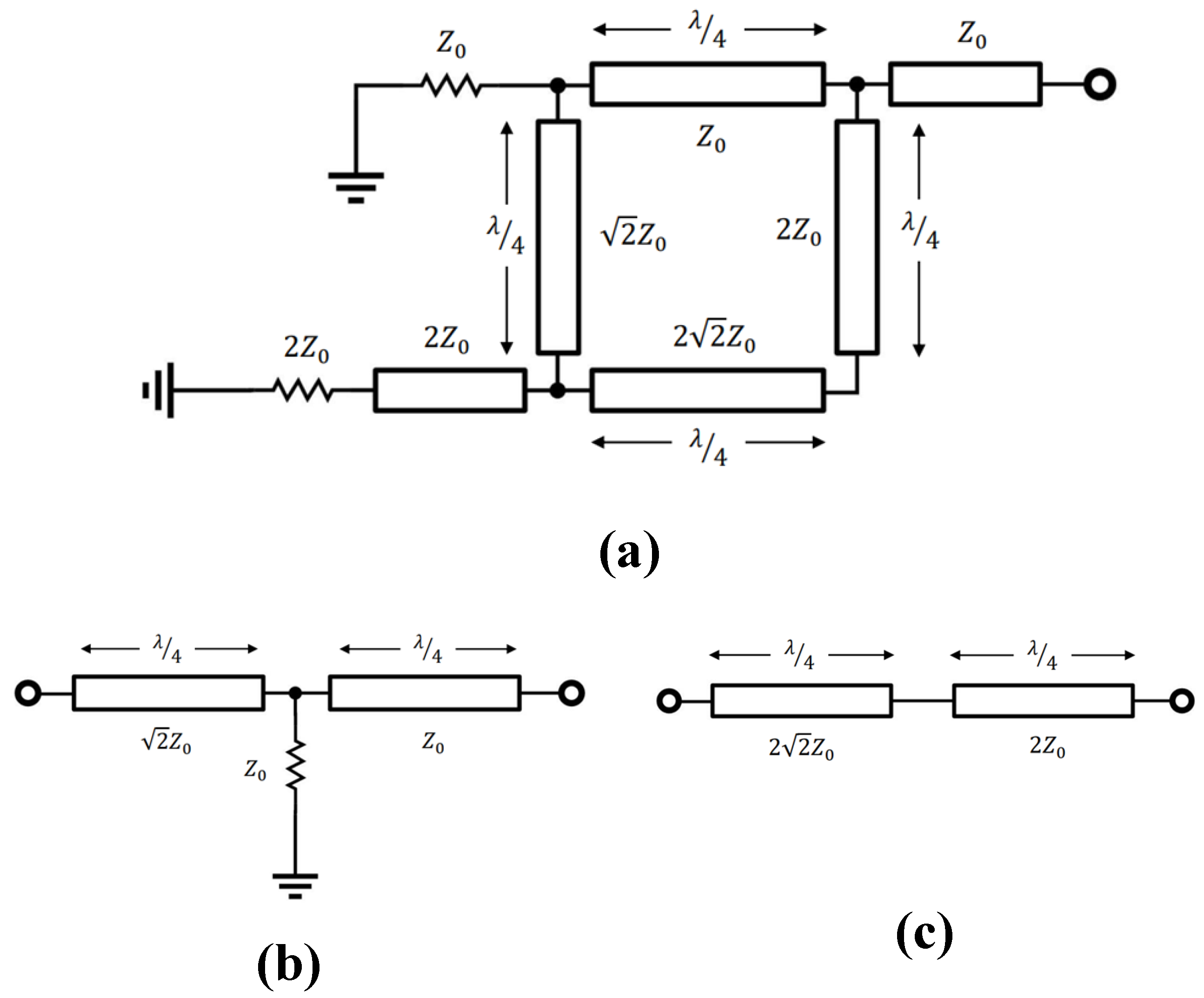
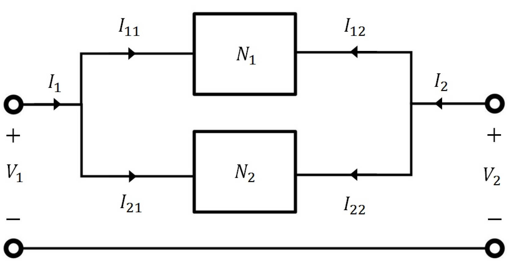
2.1. Theoritical Analysis
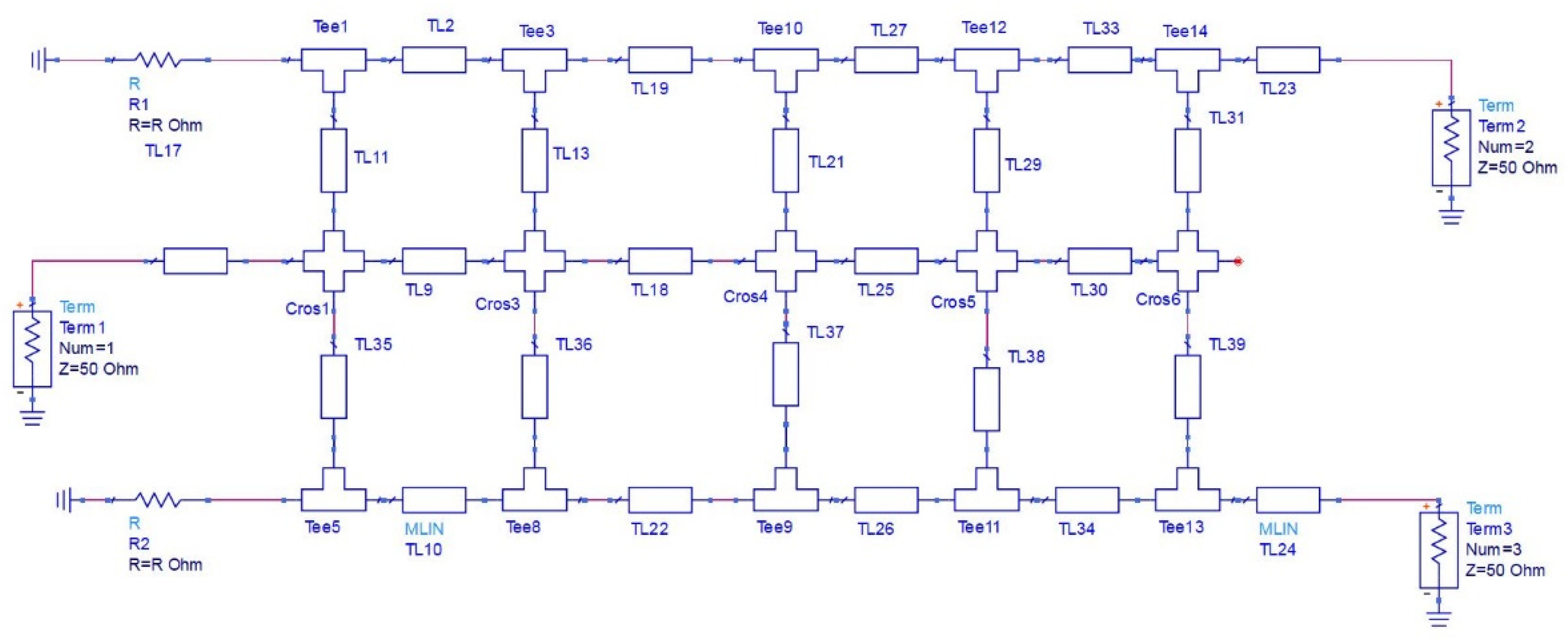
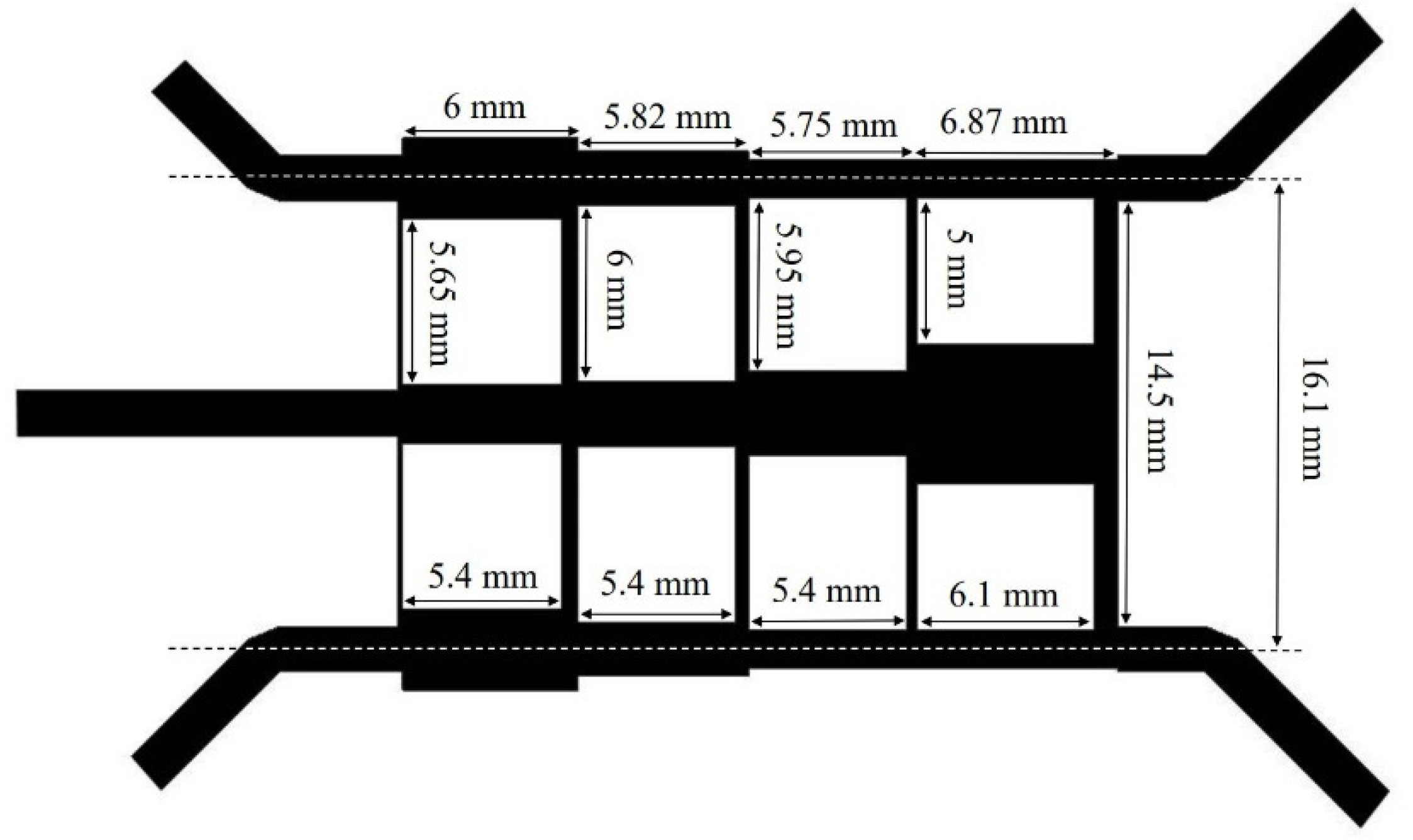
Figure 2 shows the equivalent circuit model of the proposed power divider for one section of the structure. The power reaches ports 2 and 3 with equal phase and amplitude in the divider mode. All transmission lines have the same length as a quarter wavelength. The proposed structure can be solved using even and odd analysis. Figure 3a depicts the even model and Figure 3b shows the odd model of the structure when ports 2 and 3 are excited. Figure 4a illustrates a half-circuit of the even mode that can be considered as a combination of two other circuits, which are shown in Figure 4b,c. Equations can be solved using ABCD matrix relations.
The ABCD matrix of the structure in Figure 4b is as follows:
ABCD = [ 0 j 2 Z 0 j 2 Z 0 0 ] [ 1 0 1 Z 0 1 ] [ 0 j Z 0 j Z 0 0 ] = [ 2 2 Z 0 0 1 2 ]
and the ABCD matrix of the structure in Figure 4c is as follows:
ABCD = [ 0 j 2 2 Z 0 j 2 2 Z 0 0 ] [ 0 j 2 Z 0 j 2 Z 0 0 ] = [ 2 0 0 1 2 ]
On the basis of Figure 5, considering two parallel networks of even mode half-circuits, we have the following results for the full circuit:
I 2 = I 12 + I 22
[ V 1 I 21 ] = [ 2 0 0 1 2 ] [ V 2 I 22 ]   { I 21 = 1 2 I 22 V 1 = 2 V 2 }
[ V 1 I 11 ] = [ 2 2 Z 0 0 1 2 ] [ V 2 I 12 ]   I 11 = 1 2 I 12
  I 1 I 21 = 1 2 ( I 2 I 22 )   I 1 = 1 2 I 2 + I 21 1 2 I 22 3 I 1 = 1 2 I 2
  [ V 1 I 1 ] = [ 2 0 0 1 2 ] [ V 2 I 2 ]
    [ V 2 I 2 ] = [ 1 2 0 0 2 ] [ V 1 I 1 ]
The last relation shows the ABCD matrix of the even mode, and according to the input impedance relation for Figure 4a, we have
Z i n = A Z L + B C Z L + D       Z L = 100   Ω       Z i n = 1 2 × 100 2 = 50   Ω
As a result, the circuit is matched in the even mode. For the odd mode, the circuit is simplified as shown in Figure 3b, which is fully matched due to the open circuit of the quarter wavelength transmission line.

2.2. Modeling

The schematic of the power divider was modeled in ADS software and cascaded up to four sections to provide the target bandwidth. The parametric schematic was optimized with the method of moments based on the ADS Momentum tool. The final ADS schematic for this design is illustrated in Figure 6. The final layout was imported to HFSS software for a 3D full-wave analysis and more accurate results. In HFSS, a wave port is commonly used for excitation, and the software generates a solution by exciting each wave port individually. Each mode incident on a port contains one watt of time-averaged power. Another important feature is the definition of the radiation boundary. Since this design is an open boundary problem, radiation boundaries are used to emulate a wave radiating infinitely far into space.

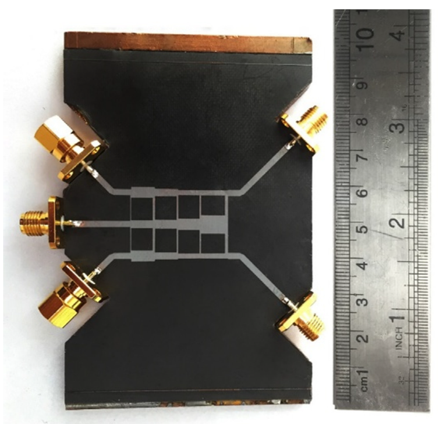
3. Results and Discussion

As mentioned, a circuit analysis was performed in ADS software, while a full-wave analysis was carried out in HFSS. Initially, a single section of the structure was designed, which was extended to a multi-section structure for a wider bandwidth in the 7–12 GHz frequency range. Figure 7 shows the final multi-section structure of the proposed power divider. The optimized dimensions are also depicted in Figure 7. The presented structure has been manufactured on a substrate in order to validate its performance. Rogers RT5880 with a dielectric permittivity of 2.2, dielectric thickness of 0.508 mm, copper thickness of 35 µm, and loss tangent of 0.0005 has been utilized as the dielectric substrate. The module has been fabricated with the standard printing process for the microstrip components. In addition, for measurement purposes, all five ports are connected to 50 ohm SMA connectors that operate up to 18 GHz. Isolated ports are terminated with available low-power SMA termination loads; however, it should be noted that in high-power applications, high-power 50 ohm resistors should be used.
Figure 8 is a photo of the fabricated power divider. The simulation and measurement results for the insertion loss and also the isolation between output ports are shown in Figure 9. For power dividers, the insertion loss is defined by the additional loss above the nominal loss due to splitting. For the proposed 3 dB power divider, the average obtained insertion loss (S21) is about 0.5 dB. The isolation between output ports (S32) is better than −15 dB. This means that a signal entering output 2 does not leak out of output 3, which is essential for most applications, such as diplexers in MIMO systems [25].
Figure 10 presents the return losses for both input and output ports. The input port (Port 1) has a perfect matching (better than −16 dB), and this value is lower than −11 dB for both output ports. If the input return loss is kept below −13 dB, the transmitted signal will not be affected by reflected signals. As one can see, there is good agreement between the simulation and measurement results.
Nonetheless, there are some differences between the simulation and experimental results. It is important to note that the SMA connectors are soldered to the implemented module and they are not simulated. That is the primary cause of these differences, especially for insertion and return losses. In addition, we have measured the isolation parameter (S32) using the available SMA termination loads as grounded resistors. It is reasonable to expect that these loads do not behave like ideal ones at such a high frequency. Finally, it should be noted that experimental results are always subject to measurement and calibration errors.

4. Conclusions

In this paper, a novel power divider is presented for both wideband and high-power applications. Cascading several sections of this power divider increases the operating frequency bandwidth for broadband performance. This design also takes advantage of grounded resistors to transfer heat to the ground, which allows it to handle more power. The proposed power divider has been analyzed, modeled, simulated, fabricated, and measured. The measured results of the prototype are in good agreement with the simulation and validate the idea. In both simulations and measurements, the designed power divider proved to have better than −15 dB of return losses and low insertion losses over a 52% fractional bandwidth (from 7 to 12 GHz). In comparison with similar works, the proposed power divider has demonstrated its high power handling and capability to simultaneously provide wide bandwidth and good isolation, making it an excellent candidate for broadband high-power applications such as satellites and radars.

Author Contributions

Conceptualization, H.T. and M.D.A.; methodology, H.T., R.K. and M.D.A.; validation, M.D.A.; formal analysis, H.T.; investigation, H.T.; resources, S.A. and M.Z.; data curation, S.A.; writing—original draft preparation, R.K.; writing—review and editing, M.D.A.; visualization, M.D.A.; supervision, M.Z.; project administration, S.A.; funding acquisition, M.Z. All authors have read and agreed to the published version of the manuscript.

Funding

This research received no external funding.

Data Availability Statement

Not applicable.

Conflicts of Interest

The authors declare no conflict of interest.

References

  1. Karimian, R.; Ardakani, M.D.; Ahmadi, S.; Zaghloul, M. Human Body Specific Absorption Rate Reduction Employing a Compact Magneto-Dielectric AMC Structure for 5G Massive-MIMO Applications. Eng 2021, 2, 501–511. [Google Scholar] [CrossRef]
  2. Lin, Y.-S.; Kao, M.-H.; Lan, K.-S. CMOS Four-Way Power Divider for W-Band Power Amplifiers. In Proceedings of the 2019 IEEE Radio and Wireless Symposium (RWS), Orlando, FL, USA, 20–23 January 2019; pp. 1–4. [Google Scholar]
  3. Karimian, R.; Tadayon, H. Compact ultra-wideband antenna with band-notched based on defected ground structure. J. Eng. 2014, 2014, 30–31. [Google Scholar] [CrossRef]
  4. Ardakani, M.D.; Farahani, M.; Akbari, M.; Tatu, S.O. A Compact Wideband Cubic Dielectric Resonator Antenna for Integrated 60-GHz MHMIC Short-range Transceivers. In Proceedings of the 2020 IEEE International Symposium on Antennas and Propagation and North American Radio Science Meeting, Toronto, ON, Canada, 5–10 July 2020; pp. 71–72. [Google Scholar]
  5. Akbari, M.; Farahani, M.; Ardakani, M.D.; Lalbakhsh, A.; Zarbakhsh, S.; Tatu, S.O.; Sebak, A.-R.; Ramahi, O.M.; Denidni, T.A. Highly Efficient Front End Direct Conversion Receiver for 28-GHz Wireless Access Point. IEEE Access 2021, 9, 88879–88893. [Google Scholar] [CrossRef]
  6. Farahani, M.; Ardakani, M.D.; Akbari, M.; Denidni, T.A.; Sebak, A.-R. Hedgehog Waveguide Phase Adjustment of Dual Left/Right-Hand Circularly-Polarized Antenna. In Proceedings of the 2020 IEEE International Symposium on Antennas and Propagation and North American Radio Science Meeting, Toronto, ON, Canada, 5–10 July 2020; pp. 221–222. [Google Scholar]
  7. Ardakani, M.D.; Tatu, S.O. V-Band Six-Port Interferometer Receiver: High Data-Rate Wireless Applications, BER and EVM Analysis, and CFO Compensation. IEEE Access 2021, 9, 160847–160854. [Google Scholar] [CrossRef]
  8. Ardakani, M.D.; Karimian, R.; Tatu, S.O. 60-GHz-band MHMIC Frequency Multiplier Module for Multi-Port Interferometer Receivers. In Proceedings of the 2021 United States National Committee of URSI National Radio Science Meeting (USNC-URSI NRSM), Boulder, CO, USA, 4–9 January 2021; pp. 230–231. [Google Scholar]
  9. Arab, H.; Chioukh, L.; Ardakani, M.D.; Dufour, S.; Tatu, S.O. Early-Stage Detection of Melanoma Skin Cancer Using Contactless Millimeter-Wave Sensors. IEEE Sens. J. 2020, 20, 7310–7317. [Google Scholar] [CrossRef]
  10. Beshary, H.; Eshrah, I.A.; Abdalla, M.A.Y.; Mohieldin, A.N. A Compact Low-Loss On-chip N-Way Wilkinson Power Divider for mm-Wave 5G Applications. In Proceedings of the 2020 IEEE 63rd International Midwest Symposium on Circuits and Systems (MWSCAS), Springfield, MA, USA, 9–12 August 2020; pp. 444–447. [Google Scholar]
  11. Karimian, R.; Ardakani, M.D.; Ahmadi, S.; Zaghloul, M. Design of a Non-Reciprocal Reconfigurable Phase Shifter for Phased Array Applications. In Proceedings of the 2021 United States National Committee of URSI National Radio Science Meeting (USNC-URSI NRSM), Boulder, CO, USA, 4–9 January 2021; pp. 190–191. [Google Scholar]
  12. Karimian, R.; Taravati, S.; Ardakani, M.D.; Ahmadi, S.; Zaghloul, M.E. Nonreciprocal-Beam Phased-Array Antennas Based on Transistor-Loaded Phase Shifters. IEEE Trans. Antennas Propag. 2021, 69, 7572–7581. [Google Scholar] [CrossRef]
  13. Park, M.; Lee, B. A dual-band Wilkinson power divider. IEEE Microw. Wirel. Compon. Lett. 2008, 18, 85–87. [Google Scholar] [CrossRef]
  14. Park, M. Dual-band Wilkinson divider with coupled output port extensions. IEEE Trans. Microw. Theory Tech. 2009, 57, 2232–2237. [Google Scholar] [CrossRef]
  15. Wu, Y.; Liu, Y.; Xue, Q. An analytical approach for a novel coupled-line dual-band Wilkinson power divider. IEEE Trans. Microw. Theory Tech. 2011, 59, 286–294. [Google Scholar] [CrossRef]
  16. Wang, X.; Ma, Z.; Ohira, M. Theory and experiment of two-section two-resistor Wilkinson power divider with two arbitrary frequency bands. IEEE Trans. Microw. Theory Tech. 2018, 66, 1291–1300. [Google Scholar] [CrossRef]
  17. Ardakani, M.D.; Souzandeh, N.; Karimian, R.; Aïssa, S.; Tatu, S.O. Accurate On-Wafer Measurement Technique for E-Band MHMIC Communication Systems. In Proceedings of the 2021 United States National Committee of URSI National Radio Science Meeting (USNC-URSI NRSM), Boulder, CO, USA, 4–9 January 2021; pp. 212–213. [Google Scholar]
  18. Gysel, U.H. A new N-way power divider/combiner suitable for high-power applications. In Proceedings of the 1975 IEEE-MTT-S International Microwave Symposium, Palo Alto, CA, USA, 2–14 May 1975; pp. 116–118. [Google Scholar]
  19. Fu, C.; He, T.; Fang, W.; Huang, W.; Fan, R.; Wang, L.; Zhang, Y.; Cao, Y. A Gysel Power Divider/Combiner with Enhanced Power-Handling Capability. Electronics 2022, 11, 2660. [Google Scholar] [CrossRef]
  20. Santhanam, S.; Palavesam, T.S. Comparative loss performance analysis of Gysel power dividers. In Proceedings of the 2021 5th International Conference on Electrical, Electronics, Communication, Computer Technologies and Optimization Techniques (ICEECCOT), Mysuru, India, 10–11 December 2021; pp. 350–355. [Google Scholar]
  21. Moulay, A.; Djerafi, T. Gysel Power Divider with Fixed Characteristic Impedance. In Proceedings of the 2020 IEEE/MTT-S International Microwave Symposium (IMS), Los Angeles, CA, USA, 18–27 June 2020; pp. 896–899. [Google Scholar]
  22. Nobandegani, A.K.; Hosseini, S.E. Gysel Power Divider Realized by Ridge Gap Waveguide Technology. IEEE Access 2021, 9, 72103–72110. [Google Scholar] [CrossRef]
  23. Zaidi, A.M.; Kanaujia, B.K.; Beg, M.T.; Kaim, V.; Mainuddin. A Dual Band Gysel Power Divider with Wide Band Ratio. In Proceedings of the 2019 IEEE Asia-Pacific Microwave Conference (APMC), Singapore, 10–13 December 2019; pp. 291–293. [Google Scholar]
  24. Shaterian, Z.; Karami Horestani, A. Ultra-wideband multi-section Wilkinson power divider. Microw. Opt. Technol. Lett. 2021, 63, 75–81. [Google Scholar] [CrossRef]
  25. Karimian, R.; Tadayon, H. Multiband MIMO antenna system with parasitic elements for WLAN and WiMAX application. Int. J. Antennas Propag. 2013, 13, 365719. [Google Scholar] [CrossRef]
Figure 1. Conventional power dividers: (a) Wilkinson power divider and (b) Gysel power divider.
Eng 03 00033 g001
Figure 2. The equivalent circuit model of one section of the proposed power divider.
Eng 03 00033 g002
Figure 3. (a) Even mode and (b) odd mode equivalent circuits of the proposed power divider.
Eng 03 00033 g003
Figure 4. The half-circuit of the even mode equivalent circuits of the proposed power divider, simplified into three separate circuits (a) overall circuit (b) equivalent T-network (c) equivalent series network.
Eng 03 00033 g004
Figure 5. Block diagram of two parallel networks.
Eng 03 00033 g005
Figure 6. A parametric subnetwork schematic design model of the power divider in ADS.
Eng 03 00033 g006
Figure 7. Prototype of the final designed power divider and its dimensions.
Eng 03 00033 g007
Figure 8. A photo of the fabricated power divider module.
Eng 03 00033 g008
Figure 9. The achieved simulation and measurement results of insertion loss and output ports’ isolation for the proposed power divider.
Eng 03 00033 g009
Figure 10. The simulated and measured return losses for the designed power divider.
Eng 03 00033 g010
Publisher’s Note: MDPI stays neutral with regard to jurisdictional claims in published maps and institutional affiliations.

