1. Introduction
The automotive market seeks weight reduction, mostly based on reducing the thickness of the material and increasing its mechanical resistance, which is only possible by a comprehensive knowledge of the mechanical behavior of the materials [
1]. This poses challenges to the stamping process, as higher levels of strength are accompanied by lower stretching limits. The first point is the reduction in the formability of the material during stretching; the second point is the influence of high strengths on deep drawing; the third is the trimming process; and the fourth is the flangeability, especially in multiphase materials prone to premature edge cracks. Premature edge cracking is currently the most challenging issue for stamping specialists, and several research works aim to develop more reliable methodologies for its prediction [
2]. In this paper, premature cracking caused by edge flanging in high-strength steels is evaluated by a literature review and examples of experiments developed by the authors.
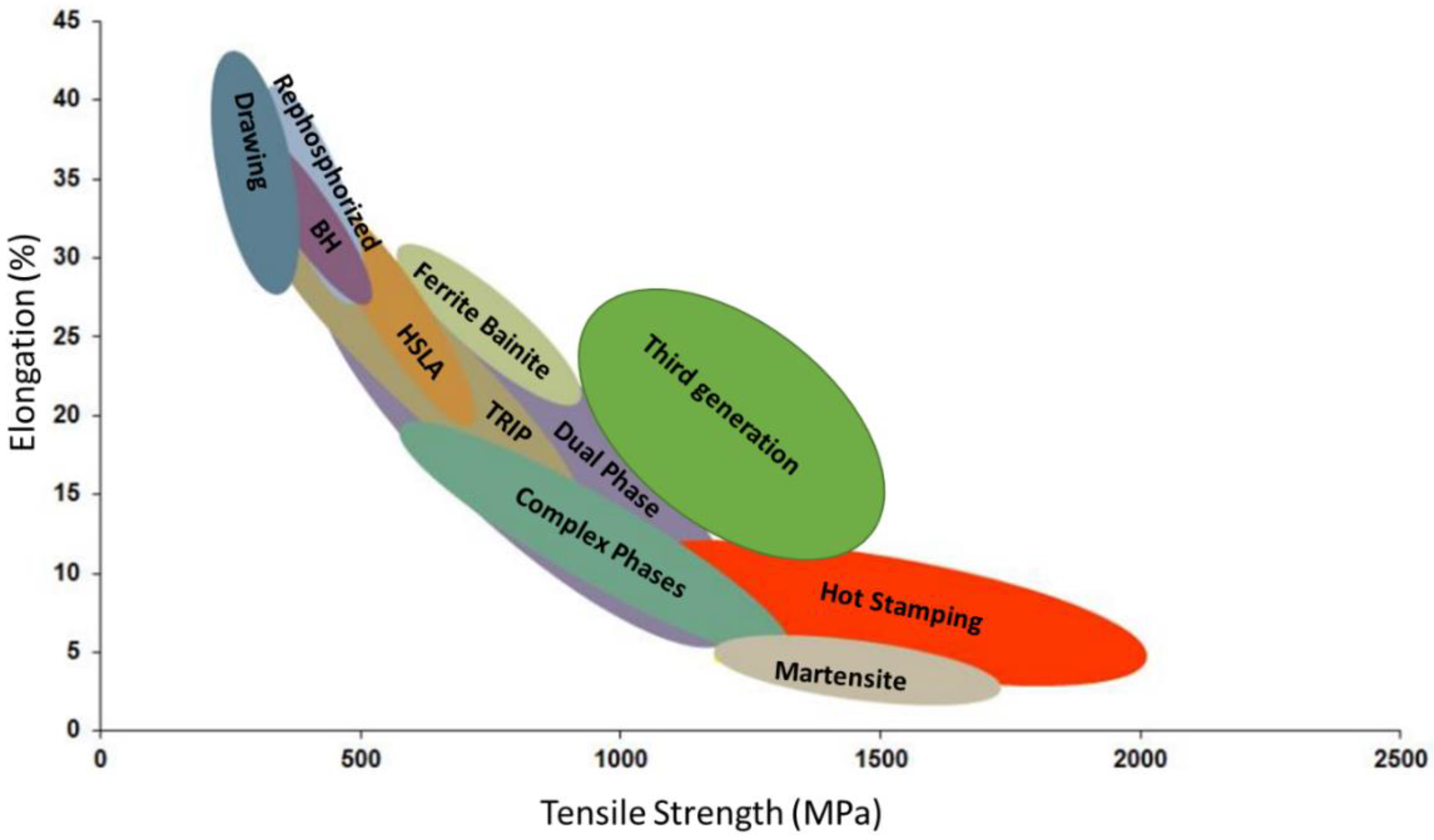
When comparing resistance versus elongation in steel grade, in
Figure 1, the most resistant materials with the capacity of good formability are in the middle of the diagram, characterized by ferrite–bainite, TRIP, complex phase, dual phase, and third generation steels, all of which are composed of more than one phase: ferrite plus martensite, austenite or bainite, or all of them. TRIP and third generation steels have another factor, deformation-induced phase transformation, from austenite to martensite [
3]. Crack propagation in ductile behavior is a process to reinitiate a crack after it has occurred. For a flat body with a similar microstructure, it is possible to have different crack tip directions independent of preexisting cracks in the region [
4].
Phase transformation, as it occurs in third generation and TRIP steel, is another complexity factor to the crack expansion phenomenon; during this transformation, the material can absorb energy, deviating the crack tip. This can sometimes influence the hole expansion results, but not always positively. When compared to other advanced high-strength steels (AHSS), it is not possible to have a direct correlation; some TRIP materials can have a worse performance than dual-phase materials with a superior mechanical strength [
5].
It is easier to understand the phenomenon of premature cracking using dual-phase 980 steels (DP980). This material is composed of martensite and ferrite, and it is possible to observe the interaction of these phases in hole expansion and the reason why it is different from monophase materials.
Moreover, finite element analysis (FEA) based solely on traditional mechanical input for AHSSs is not capable of predicting cracks. The texture of the material and the size of the grain are directly related to the crack mechanisms in the expansion of the hole [
7].
The flangeability is an intrinsic characteristic of the material and is the ability of the material to increase or decrease the perimeter of its edge during the drawing process. During stamping, it is possible for the same part to increase and decrease its perimeter edge, increasing the complexity of the evaluation and its relation to the trimming process quality [
8].
2. Damage Theories
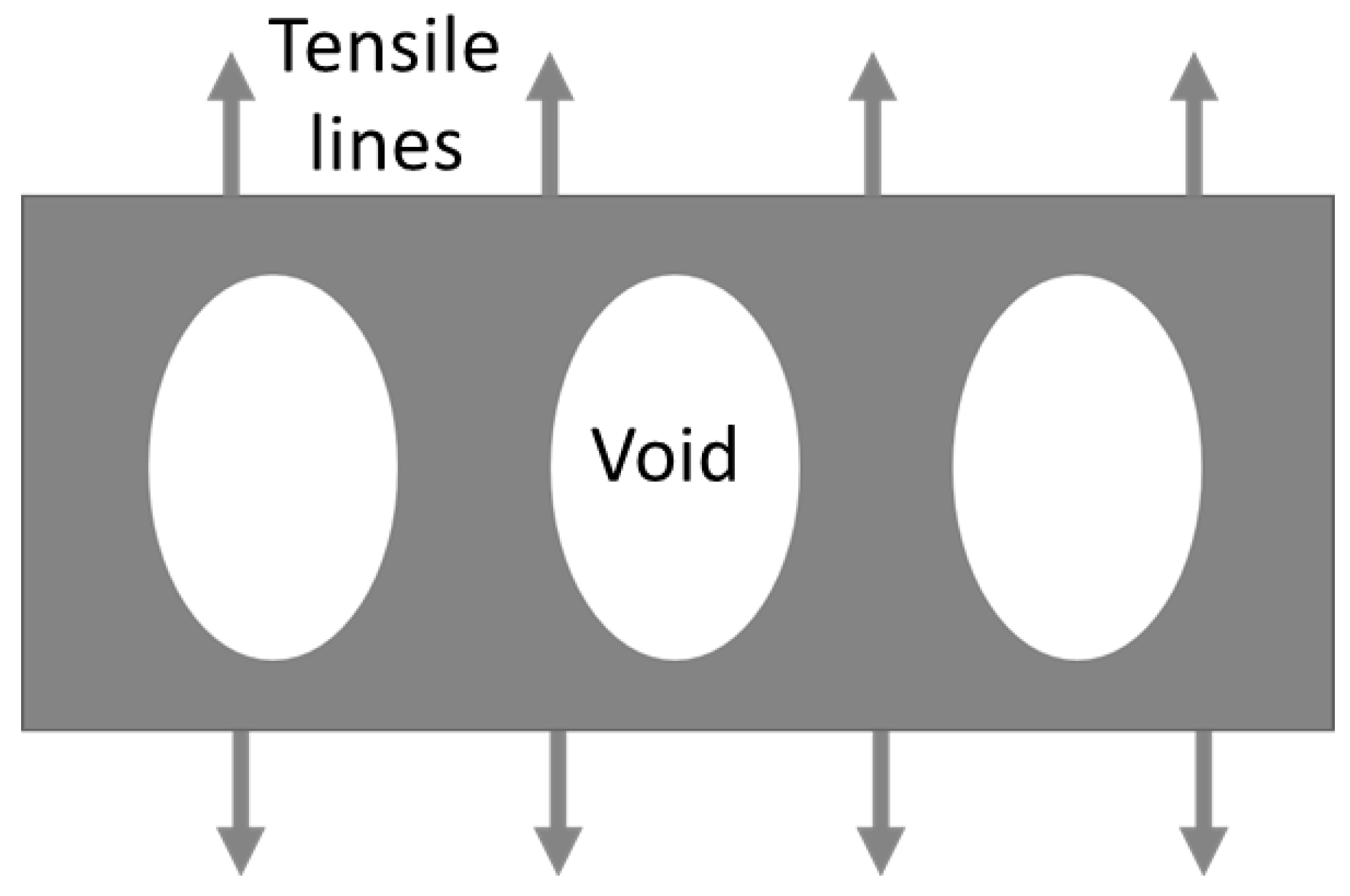
These theories are based on understanding that no material is perfectly continuous. According to Griffith, the deformation of voids inside the materials increases the inner tension inside the crystalline matrix. This increase in the tension can also be influenced by nucleation, coalescence, and void growth.
Figure 2 shows a schematic of entrapped voids that grow by the action of the tensile lines [
9]. The evaluation methods using the models of ductile fractures and plastic instability as criteria were proposed by Yoshida H. et al. (2013) [
10].
According to Gross and Seeling [
11], damage can be initiated by the nucleation, growth, and coalescence of micro-voids. Grain boundaries and different phases or inclusions can be a barrier to the dislocation movement, resulting in the nucleation of a crack. Thus, microscopic plastic flow or micro-void density generated by punching is not the dominant factor in the stretch–flange –formability of UHSS sheets.
The damage theory assumes that the voids are far from each other and do not interact. The elastic part is dominated by Hooke’s law, and the plastic part is dominated by the yield condition. Anderson [
12], based on the observations, says that void nucleation is faster under high triaxiality stresses. Void nucleation in large particles is facilitated by increasing the number of defects that cause crack initiations.
Orowan [
13] explained that Griffith’s theory for brittle-behavior solids could not be applied to ductile-behavior materials. The same author observed that laboratory tests showed that cleavage in a steel fracture can increase at slow deformation rates, different from brittle materials that grow fast. There is significant plastic deformation due to the plastic constraints that result in fractures by cleavage. Steel fractures may begin with ductile cracking followed by considerable plastic deformation. Orowan could not adjust Griffith’s theory to include plasticity. Years later, based on Orowan’s theory, Irwin [
14] improved existing theories. Irwin observed extensive plastic deformations in X-ray tests, highlighting the flaw in Griffith’s theory.
Irwin (1961) [
14] structured the analysis using stored strain energy, surface energy, and the work for plastic deformation. The analysis was based on the energy balance defined by Griffith.
Based on that principle, Cockcroft–Latham [
15] formulated the theory of maximum principal stress, using multiaxial fractures related to crack flow. Cockcroft–Latham (1968) [
15] proposed the energy fracture criterion, which states that fractures depend on the integral of the principal tensile stress. Thus, for a given material, this criterion suggests that fractures occur when the integral of the tensile stress reaches the critical value.
Later, the formula was modified by Oh, Chen, and Kobayashi [
16], proposing that it is possible to include a material factor that influences the mechanics of damage in the drawing process. D
i is a constant representing the workability of the material (1). The relationship between the material and the microstructure is expressed in Equation (1) by
Cval is the equivalent plastic strain in a fracture,
is an equivalent plastic strain, and σ is the stress.
Lee (2005) [
17] compares seven fracture criteria:
Bao–Wierzbicki model: best adapted to most mechanical tests due to Lee’s calibration in his study;
Maximum shear stress: similar to Tresca’s yield condition, but using the critical shear stress, not the shear flow stress;
Cockcroft–Lathan: as explained before, best captured the process of crack formation;
Wilkins’s model: also based on the critical value and on the critical dimension, which should be calibrated for each designated test;
Johnson–Cook fracture criterion: postulates that fractures are a function of stress triaxiality, temperature, and strain rate, but is good to express the nonconstant triaxiality loading process;
Constant equivalent strain fracture criterion: to reach the plastic strain reaches a critical value for fractures;
The fracture forming limit diagram: based on the relation between the maximum and the minimum stress, and it is highly used in stamping processes to understand critical zones for tooling processes, but it is however inappropriate to give information on the crack beginning [
17].
3. Mechanical Test
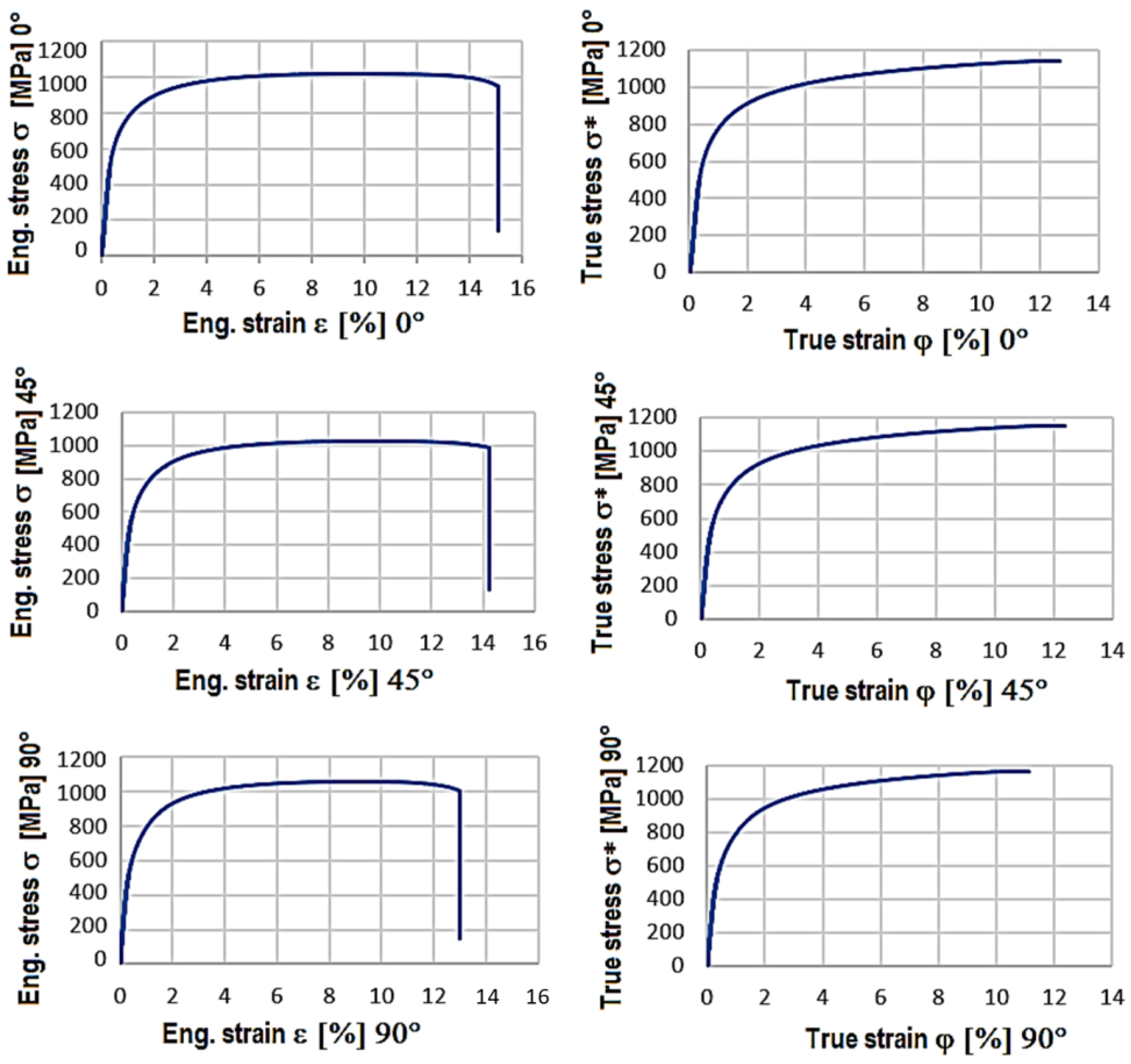
There are different mechanical tests, and the most used test to define steel properties is the tensile test.
Figure 3 represents some results for DP980 obtained by the author following ISO 6892-1 [
18].
This test could provide a basis for FEA analysis, but it is not enough; there are two tests derived from the tensile test with equal relevance: the plastic strain ratio (r) test [
19] and the tensile strain-hardening exponents [
20] test. These results quantify the capacity of the material to reduce its thickness during the tensile test and the hardening capacity of the material during the tensile test for homogeneous elongation, respectively.
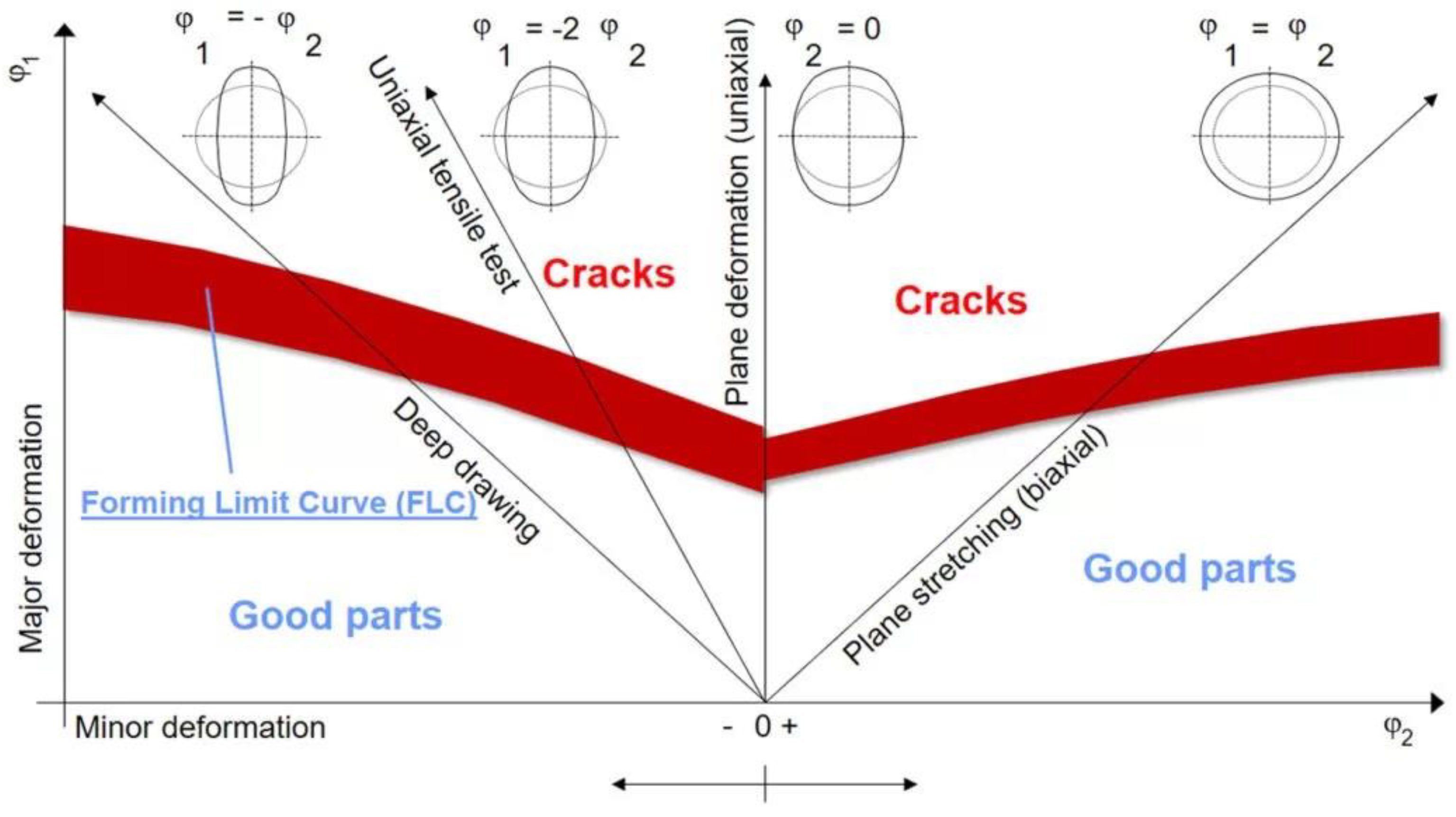
Another possibility is a forming limit diagram (FLD) [
21]. An FLD is a graphical representation of the limits to forming, i.e., the major and minor stresses where local necking occurs (
Figure 4). Different specimen geometries generate different deformation patterns, as expressed by the Nakajima test (
Figure 5) [
22].
Another example is the cup test by Erichsen. Although very simple, it is sometimes still used to understand the maximum capacity of the equiaxial deformation up to the rupture and to compare the ductility of different materials [
24]. Finally, there is the hole expansion ratio test (HERT). This test is important to compare the flangeability of sheet materials. Its characteristics are discussed in
Section 5.
4. Trimming
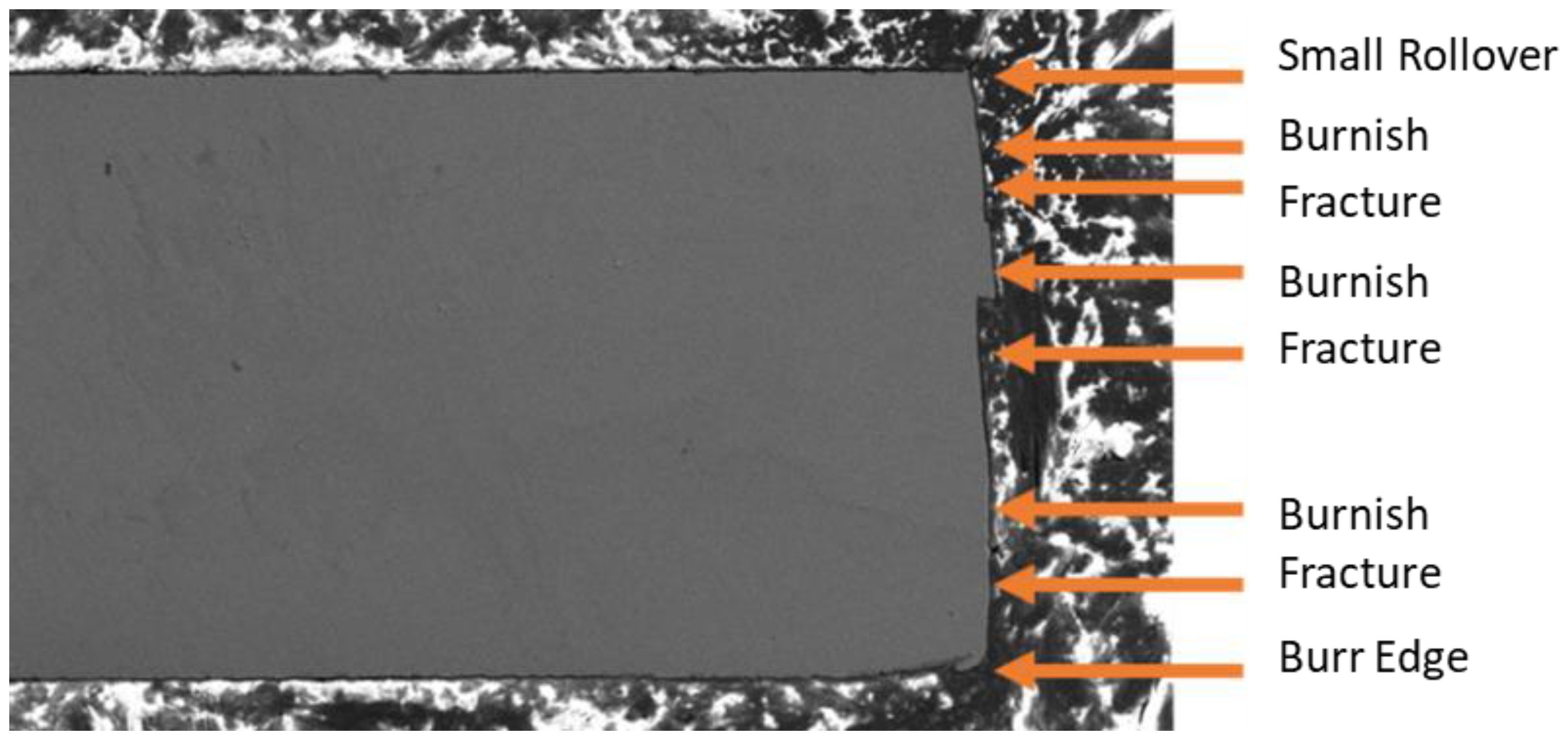
The quality of the trimming process in stamping processes must be constantly evaluated regarding the sheared edge morphology since it represents one of the greatest influencing factors on edge flangeability during the drawing process. The goal of stamping processes is to provide a part with the correct geometry, required surface quality (variables depending on application), and desired features (e.g., holes of the correct size and location, properly oriented with no splits or objectionable wrinkles).
The latter two, tearing (splits) and wrinkles, are strongly influenced by the selection of material. The trimming process occurs before hole expansion is standardized; there are thus no considerable differences between two materials of a similar resistance and elongation. In this part, the texture does not prevail over the resistance [
25]. The quality of trimming is a function of the clearance and the resistance; when clearance decreases and resistance increases, burr and rollover are reduced, but the wear of the tool increases. Four zones can be observed: rollover, burnish, fracture, and burr. When the resistance increases, it is normal to see the alternation of burnish, caused by shear stress and fractures, as shown in
Figure 6.
Different hole finishing preparation methods (e.g., punching, milling, and laser cutting) can increase the damage levels causing crack initiation at the hole edge. Maximum damage is normally caused by conventional punching, followed by milling, and later by lasers. All these processes can cause small cracks and initiate a fracture [
25]. The stretch flangeability of an ultra-high-strength steel sheet with a small ductility can be increased by improving the quality of the sheared edge [
25].
Warm and hot punching using resistance heating was developed to improve the quality of sheared edges of an ultra-high-strength steel sheet. As the heating temperature increased, the depth of the shiny burnished surface on the sheared edge increased and that of the rough fracture surface decreased. The rollover depth and burr height of the sheared edge exceeded 800 °C. Although the roughness of the burnished surface was almost constant, the roughness of the fracture surface increased by 650 °C. The local resistance heating of the shearing region was efficient for warm and hot shearing. Warm and hot shearing of ultra-high-strength steel sheets has been found to be effective for improving the quality of the sheared edge and in reducing the shearing load. Since deep drawing has problems such as fractures, seizures, and tool wear due to large deformations, bending is a preferable process for ultra-high-strength steel [
25].
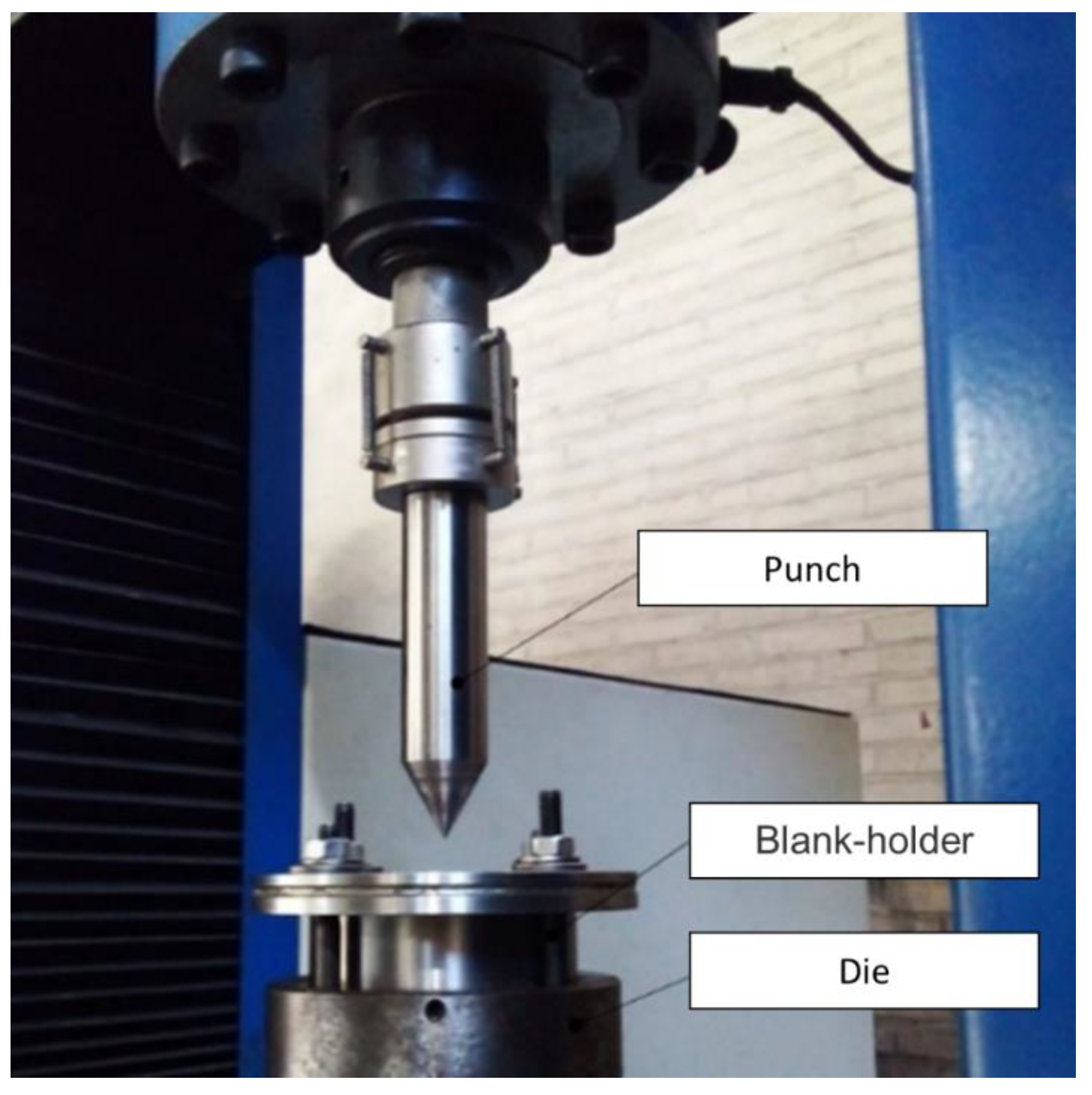
5. Hole Expansion Ratio Test (HERT)
The stretch flangeability was evaluated using the hole expansion test, and the punched hole in the sheet was expanded with a conical punch with an angle of 60°. In the hole expansion, the sheared edge was expanded uniformly in the hoop direction so that the tensile stress acted on the edge. The burr of the sheet was set without a touch of the punch on the opposite side [
26].
The first part consists of the cutting process and the hole expansion test based on standard ISO 16630 [
27]. For the trimming and hole expansion test, a universal sheet metal testing machine was used, model ZwickRoell BUP 600, with a hole expansion test tool kit (
Figure 7). After trimming, the sample was placed with the burr edge up. The test was stopped when a visible crack started. Founded on the standard in Equation (2), the diameter was measured before the test (
D0) and after the test (
De).
According to Paul (2018) [
28], it is not possible to compare the tensile test by uniaxial tests with the hole expansion, but the value of the true stress–strain is necessary to calculate using finite element analysis in the stamping process.
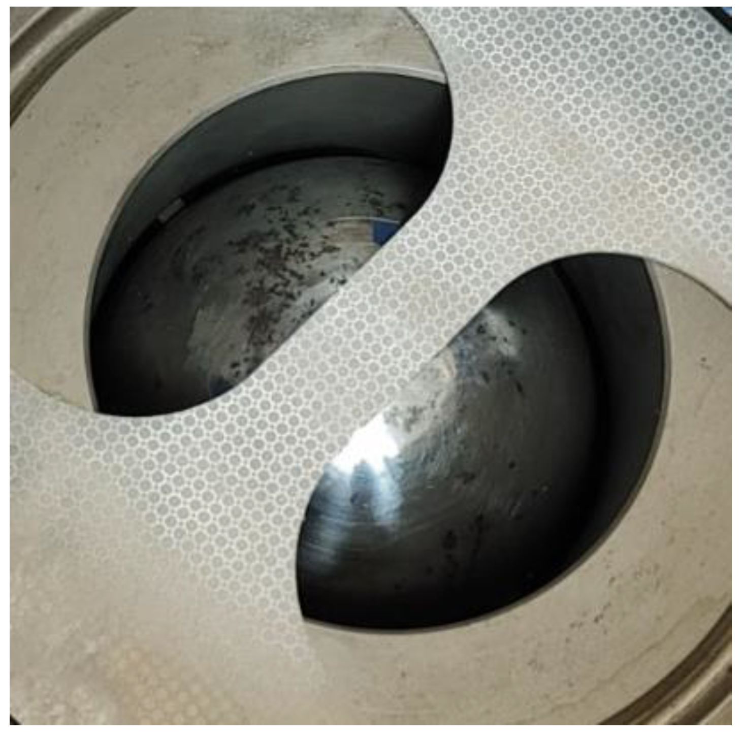
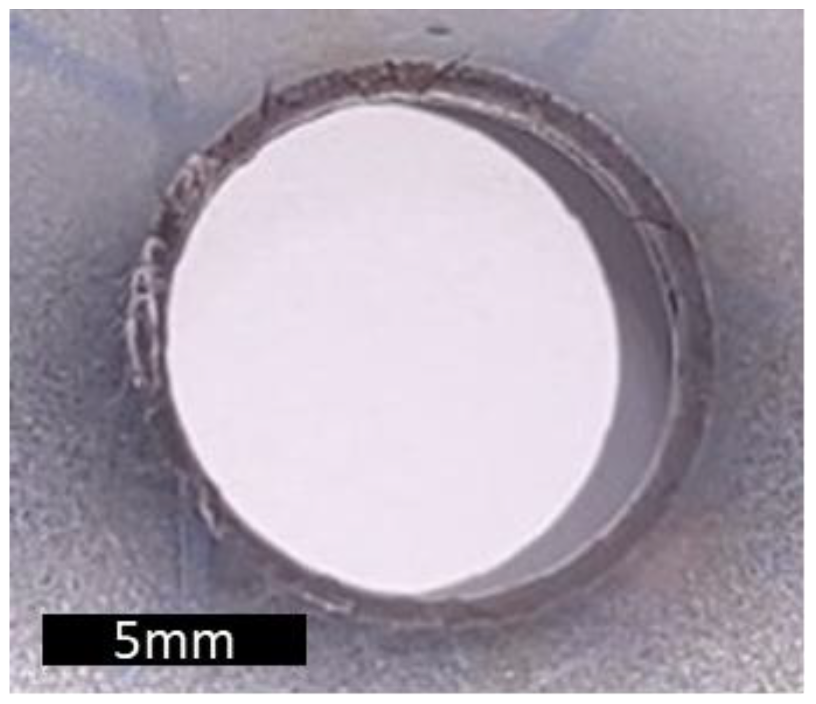
Figure 8 shows the regions in which the cracks started almost simultaneously. Since hole expansion is normally not automatized, human assistance was necessary to stop the equipment.
6. Microstructure
Raabe (2020) [
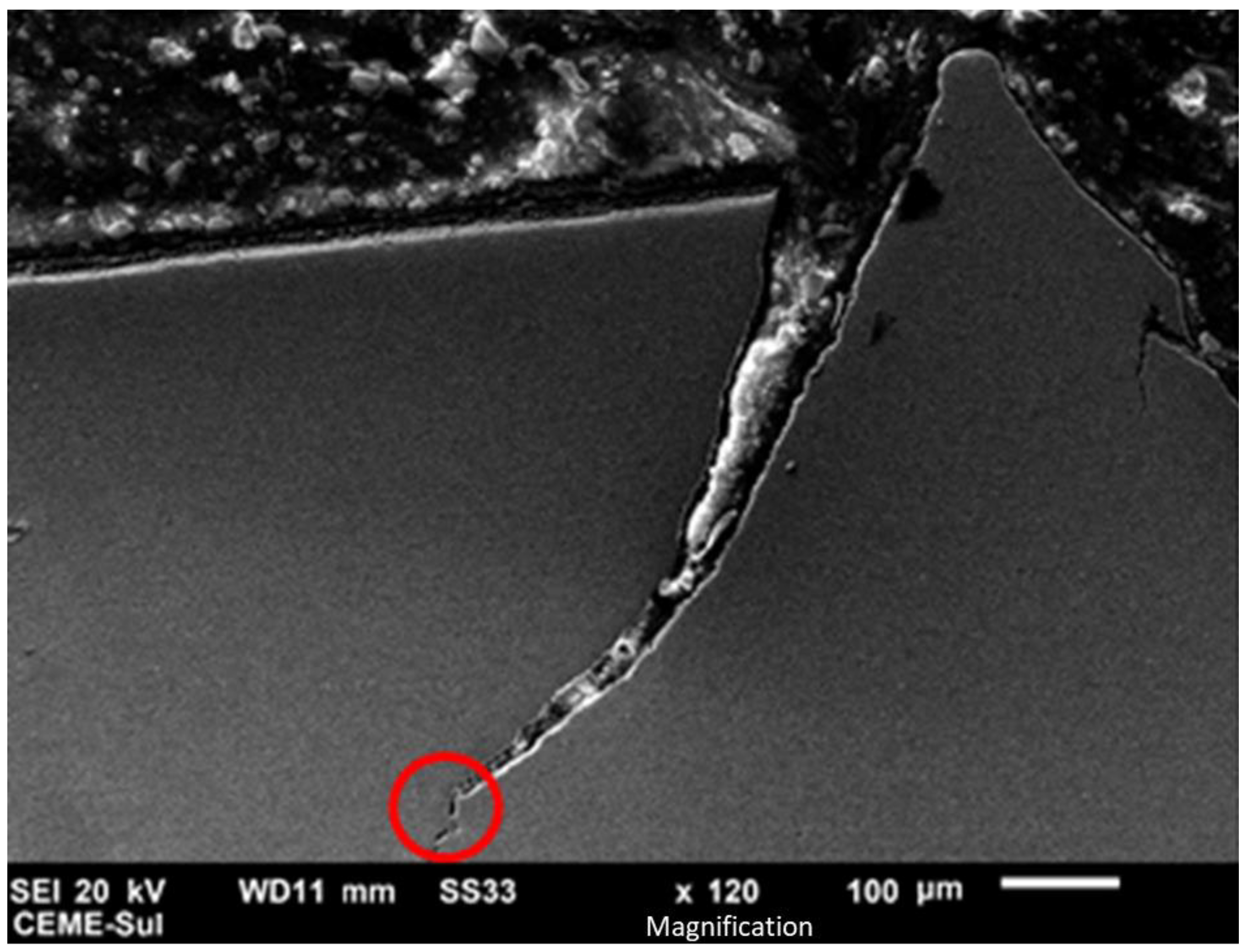
5] conducted a very detailed study on advanced high-strength steels and exposed the relation between the microstructure and hole expansion. He presented a graph containing the relation of multiphase steel elongation, oppositely proportional to the hole expansion performance. This aids in the understanding of why the present study focuses on the crack area (
Figure 9) to identify void growth [
5].
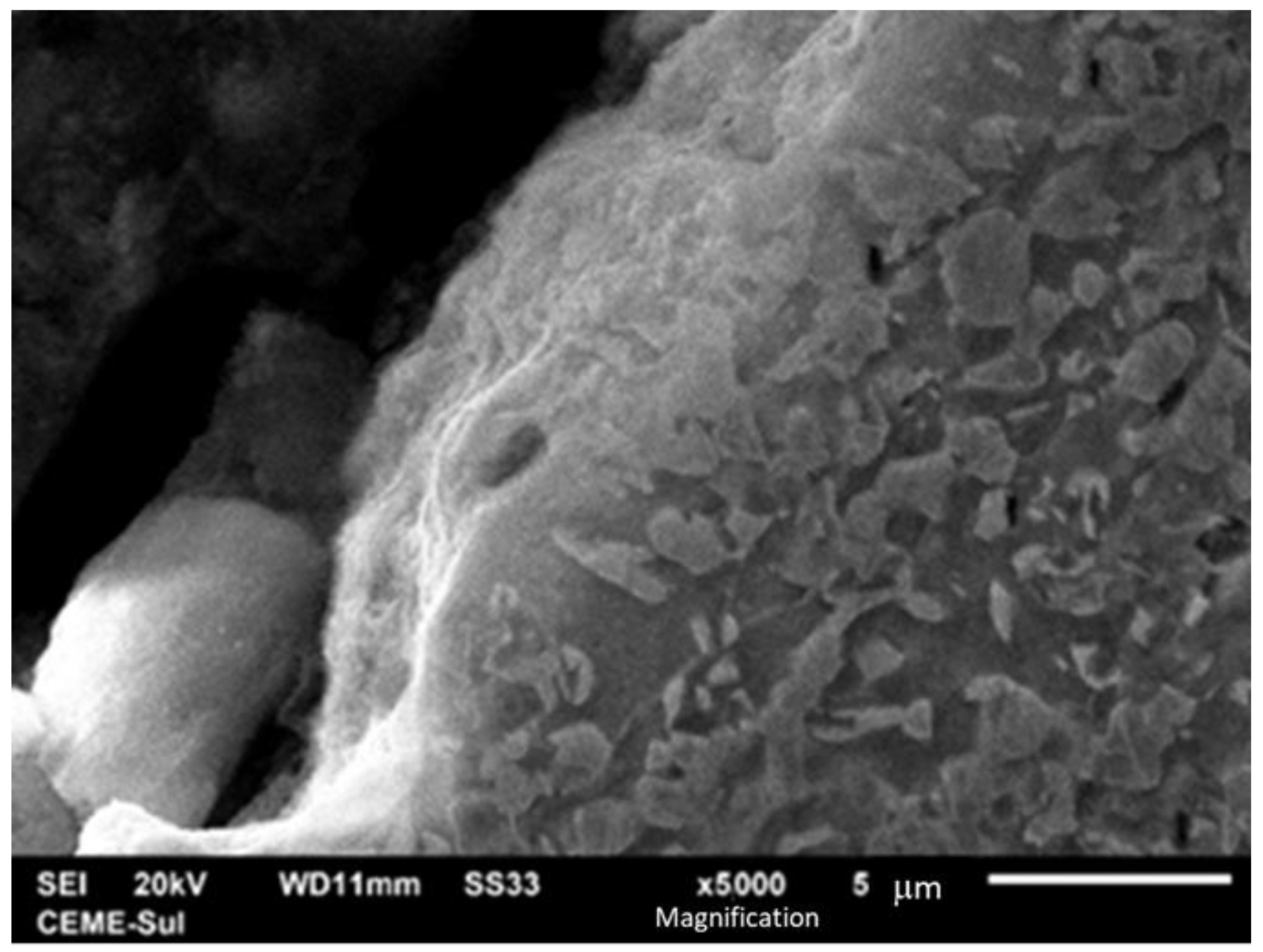
Figure 10 allows for the observation of the formation and growth of a void around the martensite. As Kim (2017) explained, it is a decohesion interface; the relationship between the grain boundary of martensite and ferrite can create a void [
30].
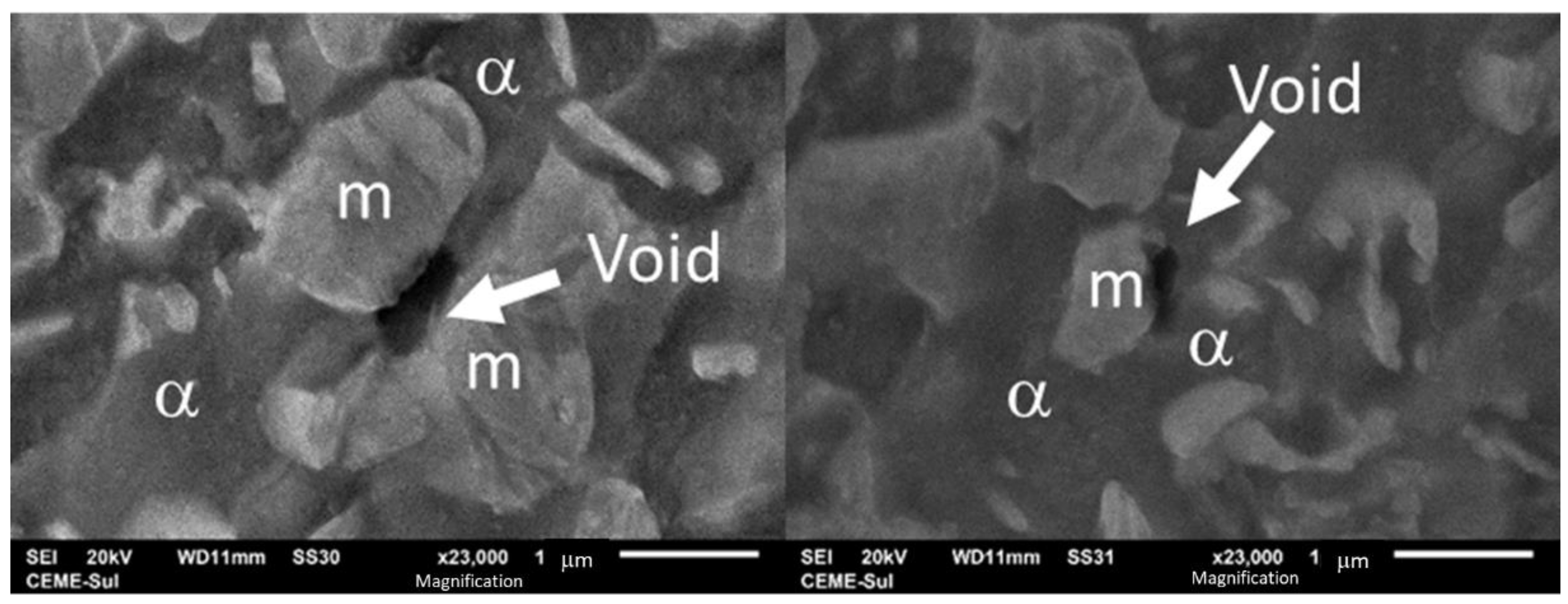
The void continued growing (
Figure 11) until a barrier was found; this barrier could be another grain of martensite. To understand this phenomenon, Zhang (2019) tested the relationship between the texture of different reduction rates and how this could influence the material resistance [
31].
The relation between premature cracking and flangeability was discussed by Akela, Kumar, and Bakachndran (2021), comparing two equivalent tensile strengths, DP 600 and HS 700 (high-strength low alloy). In their observations, the materials with a more uniform distribution and a finer-grained ferritic matrix had a greater hole expansion ratio compared to HS 700 [
32].
7. Correlation between Experimental Mechanical Testing and Simulations
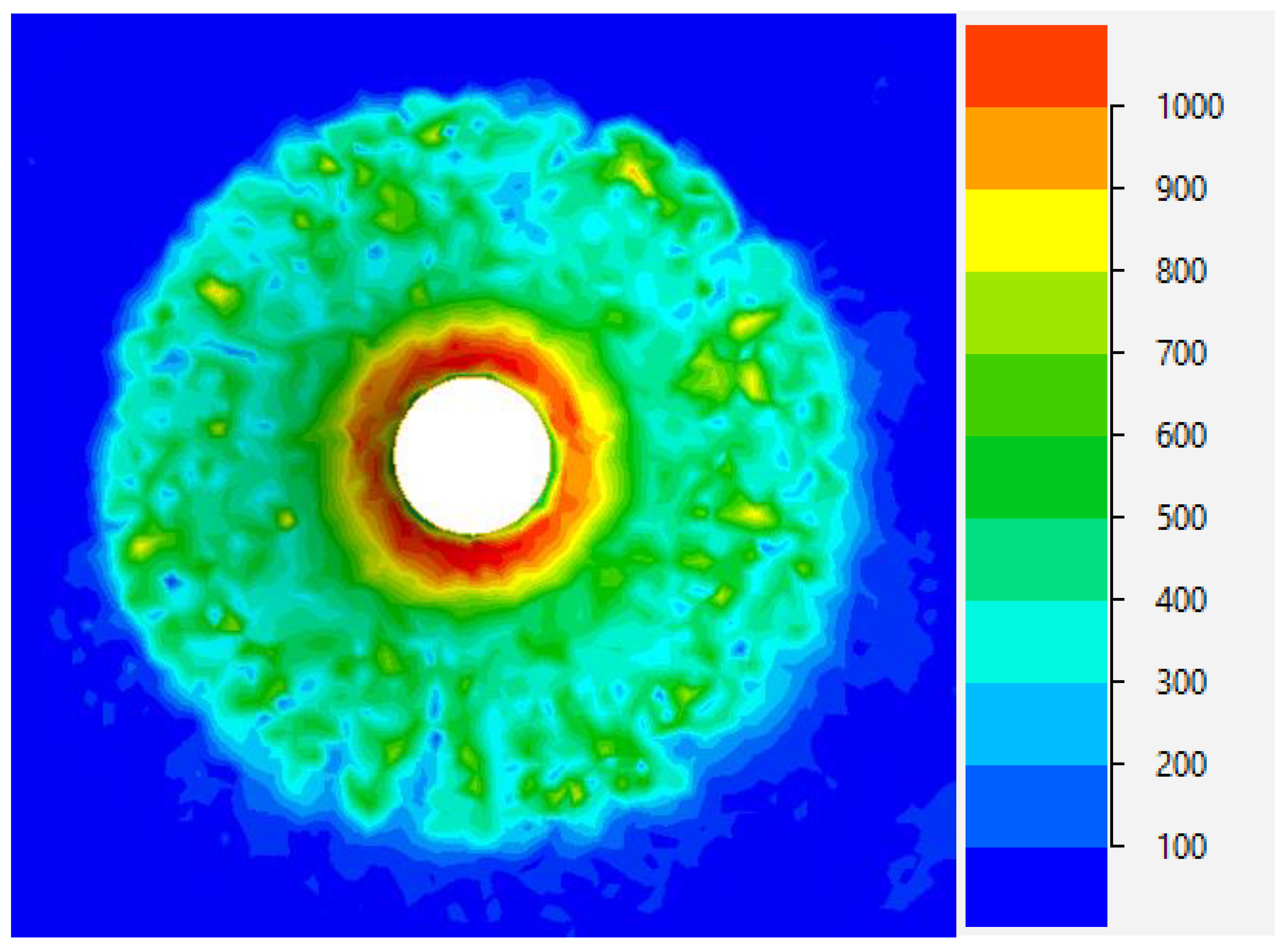
To replicate the test in a digital twin, it was necessary to recreate the intrinsic and extrinsic conditions for the material and the tool and the mechanical properties, such as flow stress, Young’s module, Poisson’s ratio, Hill’s quadratic median anisotropy for the three directions [
19], and density [
33].
Figure 12 shows a computed plot example of the principal stress σ
1 obtained after the FEM analysis carried out using the QForm FEM software.
The hole expansion test was used before to calibrate the methodology of Bao–Wierzbicki, stress-triaxiality dependent. This process allowed for the determination of the ductile damage and the progressive damage of aluminum 1050–H14 (monophasic). This was a good example of using a hybrid method to calibrate the parameters to introduce in the damage model. This exposed the need to identify a damage model that can incorporate into FEA to predict the metal-forming process cracks [
34].
There are different methods to calculate the damage criteria and evaluate damage; the method chosen for the present paper was the damage model of Cockcroft–Latham. According to the literature, this method is very accurate and is easily implemented to evaluate the workability of the material. The Cockcroft–Latham criteria relates plastic deformation and tensile stress, observing that voids grow by deformation [
35]. There are many other ways to determine the damage module such as the principle of equivalence in deformation; this principle is based on thermodynamics and expresses the possibility of understanding the microstructure applied to rheological dislocations [
36].
This is important to improve tool geometry, calculate the thickness distribution, and optimize the material flow to avoid premature failures. Some studies show that using a combination of practical and theoretical models to improve quality reduces development time and costs [
37,
38].
8. Conclusions
It is possible to understand why premature cracking occurs in multiphase steel: it derives from the decohesion interface between ferrite and martensite. However, there is still a long way to go to understand the relationship between the advanced high-strength steel microstructure and its flangeability.
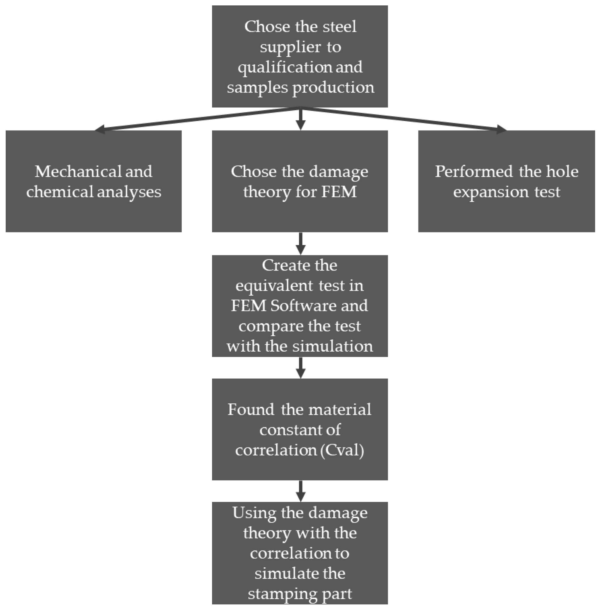
In this work, it is proposed to follow the steps shown in
Figure 13 to predict premature cracks and reduce costs and tooling setup time. However, it is necessary to follow the edge quality of the material during tool life in order to obtain satisfactory results. The hole expansion test is still very manual and depends on the accuracy of the operator and on experience to observe the start of the crack.
Although ultra-high-strength steel sheets seem promising for reducing the weight of automobiles, the stamping process is still challenging. The rise in strength leads to the increase in forming loads, spring back, and tool wear and the decrease in formability. To overcome these difficulties, improvements not only in material properties, but also in forming processes are required.
For the next step, it is possible to correlate the Cockcroft–Lathan damage theory with the hole expansion test and to determine the material intrinsic constant of the equation to calibrate the model, allowing for the prediction of premature cracks in the stamping process. It is nevertheless necessary to understand the relationships between size and distribution of the grain phases and how they interact by virtual simulations. It must be possible to extract this information from a simple microscope, reducing time and the complexity of the process. The perspective of determining this correlation is very promising. The challenge is to automatize this process and to reduce the necessity of the specialization of the operator during simulations using FEA analyses.
Author Contributions
Conceptualization, L.S.P., J.H.C.S. and G.F.B.; methodology, L.S.P.; software, L.S.P.; validation, L.S.P., J.H.C.S. and G.F.B.; formal analysis, L.S.P., J.H.C.S. and G.F.B.; investigation, L.S.P., J.H.C.S. and G.F.B.; resources, L.S.P. and J.H.C.S.; data curation, L.S.P., J.H.C.S. and G.F.B.; writing—original draft preparation, L.S.P., J.H.C.S. and G.F.B.; writing—review and editing, L.S.P. and G.F.B.; visualization, L.S.P., J.H.C.S. and G.F.B.; supervision, G.F.B.; project administration, L.S.P.; funding acquisition, L.S.P. All authors have read and agreed to the published version of the manuscript.
Funding
This research received no external funding.
Institutional Review Board Statement
Not applicable.
Informed Consent Statement
Not applicable.
Data Availability Statement
Not applicable.
Conflicts of Interest
The authors declare no conflict of interest.
References
- Banu, M.; Cao, J. Opportunities and Challenges in Metal Forming for Light Weighting: Review and Future Work. ASME J. Manuf. Sci. Eng. 2020, 142, 11081. [Google Scholar] [CrossRef]
- Paul, S.K. A critical review on hole expansion ratio. Materialia 2020, 9, 100566. [Google Scholar] [CrossRef]
- Atkins, A.G. Fracture in forming. J. Mat. Proc. Tech. 1996, 56, 609–618. [Google Scholar] [CrossRef]
- Xinyan, J.; Li, W.; Speer, J.G. Hole Expansion in Q&P, DP and TRIP Steel Sheets. Proc. Int. Symp. Automob. Steel 2013, 5, 60–67. [Google Scholar]
- Raabe, D.; Sun, B.; Da Silva, A.K.; Gault, B.; Yen, H.-W.; Sedighiani, K.; Sukumar, P.T.; Filho, I.R.S.; Katnagallu, S.; Jägle, E.; et al. Current Challenges and Opportunities in Microstructure-Related Properties of Advanced High-Strength Steels. Metall. Mater. Trans. A 2020, 51, 5517–5586. [Google Scholar] [CrossRef]
- Keeler, S.; Kimchi, M. Advanced High-Strength Steels Application Guidelines; Version 6; WordAutoSteel: Brussels, Belgium, 2017; 116p. [Google Scholar]
- Pathak, N.; Butcher, C.; Worswick, M.J.; Bellhouse, E.; Gao, J. Damage Evolution in Complex-Phase and Dual-Phase Steels during Edge Stretching. Materials 2017, 10, 346. [Google Scholar] [CrossRef] [PubMed]
- Ferreira, J.L.; Tepedino, J.O.A.; Wolff, M.A. Evaluation of the Effect of Clearance on Cutting Edge Quality and Flanging Capacity of IF, HSLA and Dual Phase Steels; SAE International Congress: São Paulo, Brazil, 2013. (In Portuguese) [Google Scholar]
- Griffith, A.A. The Phenomena of Rupture and Flow in Solids. Phil. Trans. R. Soc. Lond. A 1920, 221, 163–197. [Google Scholar]
- Yoshida, H.; Sato, K.; Matsuno, T.; Yoshida, T. Evaluation and Improving Methods of Stretch Flangeability; Nippon Steel Technical Report, No. 103; 2013; Available online: https://www.nipponsteel.com/en/tech/report/nsc/pdf/103-04.pdf (accessed on 13 November 2022).
- Gross, D.; Seeling, T. Fracture Mechanics: With an Introduction to Micromechanics, 3rd ed.; Springer: Cham, Switzerland, 2018; 362p. [Google Scholar]
- Anderson, T. Fracture Mechanics: Fundamentals and Applications, 4th ed.; CRC Press: Boca Raton, FL, USA, 2017. [Google Scholar]
- Orowan, E. Energy Criteria od Fracture: Technical Report n. 3 Massachusetts Institute of Technology; Department of Mechanical Engineering. Office of Naval Research: Arlington, VA, USA, 1954. [Google Scholar]
- Irwin, G.R. Plastic Zone Near a Crack and Fracture Toughness. In Sagamore Research Conference Proceedings; Syracuse University Research Institute: Syracuse, NY, USA, 1961; Volume 4, pp. 63–78. [Google Scholar]
- Cockcroft, M.G.; Latham, D.J. Ductility and the workability of metals. J. Inst. Met. 1968, 96, 33–39. [Google Scholar]
- Oh, S.I.; Chen, C.C.; Kobayashi, S. Ductile fracture in axisymmetric extrusion and drawing—Part 2 workability in extrusion and drawing. J. Eng. Ind. 1979, 101, 36–44. [Google Scholar] [CrossRef]
- Lee, Y.W. Fracture Prediction in Metal Sheets. Ph.D. Thesis, Massachusetts Institute of Technology, Cambridge, MA, USA, 2005; p. 411. [Google Scholar]
- ISO 6892-1; Metallic Materials. Tensile Testing Method of Test at Room Temperature, 3rd ed. ISO: Geneva, Switzerland, 2019.
- ASTM E517-16; Standard Test Method for Plastic Strain Ratio r for Sheet Metal. ISO: Geneva, Switzerland, 2010.
- ASTM E646-16; Standard Test Method for Tensile Strain-Hardening Exponents (n-Values) of Metallic Sheet Materials. ISO: Geneva, Switzerland, 2016.
- ISO Standard 12004; Metallic Materials—Guidelines for the Determination of FLD. ISO: Geneva, Switzerland, 2008.
- Gutiérrez, D.; Lara, A.; Casellas, D.; Prado, J.M. Effect of strain paths on formability evaluation of TRIP steels. Adv. Mater. Res. 2010, 89–91, 214–219. [Google Scholar] [CrossRef]
- Souza, J.H.C. Robustness in Stampings Production: The Role of Mechanical Properties for Sheet Metal Forming–Part I. Forming World. 2022. Available online: https://formingworld.com/mechanical-properties-robust-stampings-1 (accessed on 13 November 2022).
- ISO 20482; Metallic Materials—Sheet and Strip—Erichsen Cupping Test. ISO: Geneva, Switzerland, 2013.
- Hasegawa, K.; Kawamura, K.; Urabe, T.; Hosoya, Y. Effects of Microstructure on Stretch-flange-formability of 980 MPa Grade Cold-rolled Ultra High Strength Steel Sheets. ISIJ Int. 2004, 44, 603–609. [Google Scholar] [CrossRef]
- Mori, K.-I.; Abe, Y.; Suzui, Y. Improvement of stretch flangeability of ultra-high strength steel sheet by smoothing of sheared edge. J. Mater. Process. Technol. 2010, 210, 653–659. [Google Scholar] [CrossRef]
- ISO 16630; Metallic Materials—Sheet and Strip—Hole Expanding Test, 2nd ed. ISO: Geneva, Switzerland, 2017.
- Paul, S.K. Fundamental aspect of stretch-flangeability of sheet metals. Proc. Inst. Mech. Eng. Part B J. Eng. Manuf. 2019, 233, 2115–2119. [Google Scholar] [CrossRef]
- Rosiak, A.; dos Santos, T.G.; Wermuth, D.P.; Alba, D.R.; Riffel, M.H.; da Rocha, R.P.; Schaeffer, L. Análise Numérica e Experimental da Expansão de Furo do Aço 22MNB5 (Portuguese). 41st SENAFOR, Porto Alegre, RS. 2022, pp. 1–16. Available online: https://bdtd.ibict.br/vufind/Record/URGS_266c09a28f1f8814c0cc01bc552558c9 (accessed on 13 November 2022).
- Kim, D.K.; Kim, E.-Y.; Han, J.; Woo, W.; Choi, S.-H. Effect of microstructural factors on void formation by ferrite/martensite interface decohesion in DP980 steel under uniaxial tension. Int. J. Plast. 2017, 94, 3–23. [Google Scholar] [CrossRef]
- Zhang, Y.; Yuan, Q.; Ye, J.; Weng, X.; Wang, Z. Effect of cold rolling reduction on microstructure, mechanical properties, and texture of deep drawing dual-phase (DP) steel. Mater. Res. Express 2019, 6, 096530. [Google Scholar] [CrossRef]
- Akela, A.K.; Kumar, D.S.; Balachandran, G. Hole Expansion Test and Characterization of High-Strength Hot-Rolled Steel Strip. Trans. Indian Inst. Met. Ed. 2021, 75, 625–633. [Google Scholar] [CrossRef]
- Wagoner, R.H.; Chenot, J.-L. Metal Forming Analysis; Cambridge University: Cambridge, UK, 2001; pp. 1–46, 286–340. [Google Scholar]
- Soussi, H.; Krichen, A. Calibration method of ductile damage model based on hybrid experimental-numerical analysis of uniaxial tensile and hole-expansion tests. Eng. Fract. Mech. 2008, 200, 218–233. [Google Scholar] [CrossRef]
- Dieter, G.E.; Kuhn, H.A.; Semiatin, S.L. Handbook of Workability and Process Design; ASM International: Almere, The Netherlands, 2003; pp. 3–19. [Google Scholar]
- Lemaitre, J.; Chaboche, J.-L.; Benallal, A.; Desmorat, R. Mecánique des Matériaux Solides, 3rd ed.; Dunod: Paris, France, 2009; p. 300. [Google Scholar]
- Damoulis, G.L.; Gomes, E.; Batalha, G.F. Analysis of the Industrial Sheet Metal Forming Process using the Forming Limit Diagram (FLD) through Computer Simulations as Integrated Tool in Car Body Development. Int. J. Mech. Sci. 2007, 210–217. [Google Scholar]
- Damoulis, G.L.; Gomes, E.; Batalha, G.F. Combined finite element: Forming limit diagram methodology for the development of automotive body stamped parts. Int. J. Mechatron. Manuf. Syst. 2008, 1, 264–281. [Google Scholar] [CrossRef]
| Publisher’s Note: MDPI stays neutral with regard to jurisdictional claims in published maps and institutional affiliations. |
© 2022 by the authors. Licensee MDPI, Basel, Switzerland. This article is an open access article distributed under the terms and conditions of the Creative Commons Attribution (CC BY) license (https://creativecommons.org/licenses/by/4.0/).


