Abstract
This study explores the transmission characteristics between the links of UV(ultraviolet)-network communication under mobile conditions. Utilizing the prevalent UV-network communication network topology as a foundation, a UV-network communication model tailored to mobile scenarios was developed. This model includes a method for calculating the impulse response of the system, focusing specifically on three common network topology structures: two parallel links, co-address of the originating link, and co-address of the receiving link. The simulation and analysis conducted in this study examine the impact of various factors on the system’s impulse response, such as receiver movement speed, geometric parameters of the receivers, link spacing, and the angle between links. The results indicate that receiver movement speed significantly influences pulse response fading, with faster speeds resulting in more severe fading. Additionally, in parallel links, smaller link spacing results in stronger impulse response. Furthermore, a smaller angle between the originating and receiving co-addresses results in increased inter-link interference. The study findings in this paper will lay the foundation for the study of UV mobile self-organizing networks.
1. Introduction
Ultraviolet communication (UVC) is a new optical communication technology that enables non-line-of-sight (NLOS) transmission based on the scattering of ultraviolet (UV) light by aerosol particles in air and atmospheric molecules [1]. The ozone layer’s strong absorption of sun-blind UV light results in minimal UV light in the near-Earth solar spectrum within this band. As a result, UV light communication in this band offers advantages such as minimal background noise, no requirement for direct transmission, robust anti-jamming capabilities, and the ability to operate in all weather conditions. These factors make point-to-point communication highly efficient and reliable in this specific UV light band [2,3]. However, point-to-point communication technology has the problems of short communication distance and small transmission range, which makes it difficult to meet the current demand for long-distance communication. To address this issue, building an ultraviolet mobile communication network is an effective way to increase its transmission range.
Ultraviolet networking is an important component in the study of ultraviolet communication. Currently, UV networking techniques primarily focus on fixed network nodes and known network topology. Ke et al. proposed a method to combine UV light with a self-organizing ad hoc network to enhance the transmission distance of UV light [4]. Additionally, Li et al. proposed an anti-noise relay link scheme for UV communication to address challenges related to limited radiant energy of light source equipment and attenuation in atmospheric environments [5]. Pan et al. designed and demonstrated a NLOS UV scattering communication network system, where a beacon-enabled time division multiple access (TDMA) scheme was adopted [6]. Zhao et al. simulated the link interference model under multiple interference scenarios in wireless UV optical communication. Their findings indicated that the primary factors influencing the channel bit error rate (BER) are the location of the interfering source and the size of the effective scatter volume [7].
The impulse response refers to the time response generated by a pulse applied to the input. In the process of ultraviolet optical communication, the scattering of photons at different points and the subsequent transmission paths after scattering by common scatterers result in varying arrival times at the receiving end. Additionally, the occurrence of multiple scattering can lead to pulse broadening of the received signal. Therefore, the study of impulse response of the UVC system is crucial for addressing inter-code crosstalk, reducing system BER, and enhancing data transmission rates in ultraviolet optical networking communication. Cao et al. proposed a novel single-scatter channel impulse response (CIR) model in the spherical coordinate system, which is more natural and comprehensible than the prolate-spheroidal coordinate system in practical applications. Additionally, the results of the widely accepted Monte-Carlo (MC)-based channel model of NLOS UVC were provided to verify the proposed single-scatter CIR model [8]. Additionally, Chen et al. developed a short-range NLOS UVC experimental platform to investigate the impact of geometrical parameter settings on pulse broadening within the system [9]. Luo analyzed the effects of receiving mode and communication distance on channel attenuation and pulse spreading under atmospheric conditions [10]. Qiang et al. calculated the time-domain distributions of received signals utilizing the UV transmission model to explore the impact of pulse spreading on system BER [11]. Furthermore, Wang et al. developed an expression for the impulse response in dusty weather conditions and examined the relationship between visibility levels, the time delay, and the broadening of the laser pulse under dusty weather conditions [12]. Leveraging the wireless UV single-scattering impulse response model, Taifei et al. analyzed the effects of cohesive particles as well as relative humidity on the UV impulse response and path loss [13]. Tianet et al. were the first to propose the UV LOS channel model when obstacles exist. In addition, the impulse response time expression of the LOS channel with obstacles was also derived [14]. Summarizing the existing research content mentioned above, it can be found that most of the impulse response research focuses on fixed-node communication, while in the practical application of UVC, there may be a demand for mobile communication.
To explore UV optical networking communication in mobile scenarios, we developed a UV optical communication link model for mobile scenarios based on the UV multiple scattering theory and utilizing the Monte-Carlo (MC) method [15]. By establishing the impulse response calculation formula for the system, we aim to understand how the movement of UV nodes impacts the system’s impulse response. We focus on simulating and analyzing the impact of various factors, such as link spacing, receiver moving speed, inter-link angle, and receiver structure parameters on the system’s impulse response across three prevailing networking typologies.
2. Theoretical Basis
2.1. Channel Model
This study utilizes the MC photon pointing probability method to analyze the impulse response of a receiver at a known position. By applying our previously reported method [16], we calculated the scattering point of a photon at any moment, which in turn enabled us to determine the position of the receiver at the time the photon was captured. This process enabled us to obtain the impulse response of the system as the receiver moved.
The modified transmission model of the MC method, as shown in Figure 1, involved a set of transmitter and receiver nodes denoted as T and R, respectively, positioned at a distance . The light cone of the transmitter and field-of-view cone of the receiver are denoted as and , respectively; denote the elevation angles of T and R, respectively; and represent the off-axis angles of and , respectively. represent the semi-emission angles of the transmitter and receiver, respectively. , , and denote the scattering points. is the angle at which the original coordinate system is rotated clockwise with the coordinates as the axis ; is the angle at which the coordinate system continues to rotate clockwise with the axis; is the new coordinate system; C is the angle between the transmission direction of the photon and the positive direction of the coordinate axis; is the angle between the transmission direction of the photon after scattering at point and the incident direction; is a new coordinate system constructed continuously. is the angle between the and the central axis of R.
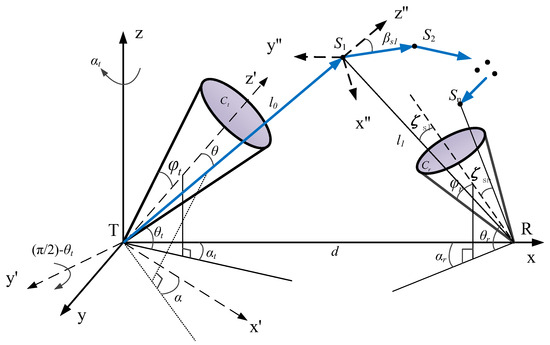
Figure 1.
NLOS UV multiple scattering propagation model.
Assume that transmitter T emits M photons, and their movement is simulated to determine the position of the scattering point of , and compute the probability of a photon being received after scattering. The photons persist in the trajectory toward the next scattering point, recalculating the probability of being received after each scattering event, particularly in cases of multiple scattering. When the arrival or survival probability of the photon is below a certain threshold, the photon is subsequently discarded. If the photons are scattered once before arriving at R, the total transmission distance L experienced by the photons is . If the photons undergo scattering events, the photon has traveled a total distance of from the transmitter to the receiver. This can be illustrated as follows [17]:
where denotes the distance from the transmitter to the scatter point of , represents the distance from the scatter point of to the receiver, and represents the distance from to . Therefore, the time taken for a photon to travel from the transmitter to the receiver is expressed as , where represents the speed of light.
Assuming a series of evenly distributed time nodes on the timeline, denoted as , being an integer with representing the interval between two time nodes, indicates that the photon arrives at the receiver at the th time interval. Assuming the transmitter emits M photons, each potentially undergoes at most scattering events. The impulse response at the receiver can be expressed as follows [18]:
where represents the probability that a photon undergoes scattering events before finally reaching the receiver. Refer to [16] for a detailed calculation of .
2.2. Modeling of UV Link Interference
To address the issue of mobile Multi-User Interference (MUI) in NLOS networks under mobile scenarios, this study introduces three common transmitter and receiver link models within typical networking environments, based on networking topology structure. These models are parallel links, transmitter co-addressed links, and receiver co-addressed links, as shown in Figure 2. This study also examines the impact of various parameters on the impulse response.

Figure 2.
Communication link model of UV networking: (a) parallel link, (b) transmitter co-addressed link, and (c) receiver co-addressed link.
In the predefined scenario, a signal source and an interference source are present at each receiver. T1 is a source of receiver R1, and T2 is a source of interference to R1; similarly, T2 is a signal source to R2, and T1 is a source of interference to R2. Define T1–R1 as Link 1 and T2–R2 as Link 2.
2.3. Research Methodology
In this paper, the following approach is taken for the study. To illustrate, consider the scenario of parallel links: T1 is fixed at the transmitter, T2 is fixed at , R1 represents the receiver located at , and R2 is located at . When T1 and T2 emit photons, the receiver begins to move closer to or farther from the link. The probability of photons reaching the receiver through single or multiple scattering is calculated, and the system’s pulse response is simulated using the MC method.
In Figure 3, when T1 or T2 emits a photon and the receiver starts moving at speed toward the positive x-axis, this photon will be received when it reaches simultaneously with the receiver. Because the scatter point position, moving speed and direction of R1/R2, and the speed of light are known, the new position of the receiver can be determined. The impulse response of the system is then obtained using Equation (2). Notably, the photon energy received by R1 from T1 is considered a useful signal, whereas the photon energy received by T2 is considered the interfering signal. The same applies to R2.
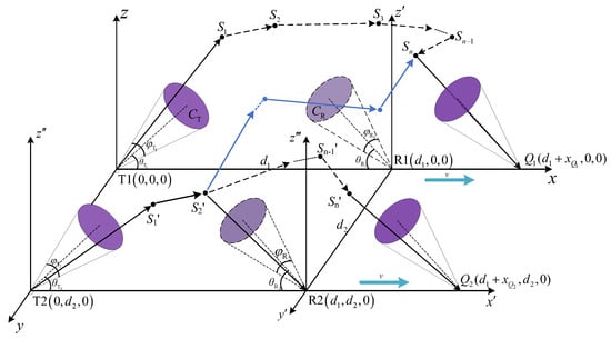
Figure 3.
Mobile model of receiver under parallel link.
Co-addressing scenarios are explored based on this research idea, with the position of being a prerequisite for investigating the impulse response. The complete expression for the solution of the point is provided below.
We assumed that photons emitted from T1 or T2 underwent scattering events, with the coordinates of each scattering point being and , and , , and representing travel distances of the receiver along the , , and axes directions, respectively. For example, in the case of Link 1, the time taken for the photon to reach the point is the same for both the photon and R1. Equation (3) is derived based on this condition [16].
The specific derivation process is divided into three cases, according to Figure 2.
2.3.1. Parallel Link
In the parallel link, the scattered photons emitted by T1 and T2 may be received by R1. In this case, the coordinates of are and those of are . The time for the photons to travel from T1 to is expressed using Equation (4), whereas the time for the receiver to travel from R1 to is expressed using Equation (5).
where denotes the distance of photon motion before the photon undergoes scattering events, expressed as follows:
where represents the straight-line distance between two points, and represents the distance between the scatter and . From and , we obtain using Equation (3):
and:
With the coordinate of being determined, the position of is known. The above equation applies to R1 and R2 moving left or right in a parallel link. The calculation method of coordinate is similar to that of ; therefore, the calculation of is not repeated.
When the receiver node moves on the z-axis, and the coordinates of are , this is substituted in Equation (3) to obtain the following:
Therefore, is expressed as follows:
and:
2.3.2. Transmitter Co-Addressed Link
In this scenario, T1 and T2 are fixed at the origin of the coordinate system, with R1 located at and R2 located at . Because the calculation for the T1–R1 link is similar to that of the parallel link, we only calculate the coordinate of when the angle between the links is acute or obtuse.
Because , we have the following:
And because , is expressed as follows:
and:
This result can be applied to the scenario of R2 in the direction of the T2–R2 link, toward and away from T2.
2.3.3. Receiver Co-Addressed Link
The simulation idea of this scenario is to fix T1 and T2 at a distance from the origin of the coordinate system; the T1 coordinates are , and the T2 coordinates are , with R1 and R2 located at the origin of the coordinate system. The transmitter remains static whereas the receiver moves along the link direction. We vary the receiver’s speed, the angle between the links, and the elevation difference to analyze the impact of the pulse response.
The equations for are similar to those of the transmitter co-addressed link.
Through the aforementioned derivation process, we obtain the new position coordinates of after movement. The coordinate position of the receiver is updated to , with the impulse response of the system obtained using the MC method. The aforementioned data allow for the analysis of the relationship between the motion parameters of the receiver, the system’s geometric parameters, and the transmission characteristics.
3. Simulation Analysis
In this section, we simulate the impact of the receiver’s speed on the impulse response of the T1–R1 and T2–R1 links, including parallel and co-addressed link scenarios, with the receiver moving in the plane and z-axis directions. Some simulation parameters are listed in Table 1 [19,20].

Table 1.
Some of the simulation parameters of UV communication system in mobile scenario.
3.1. Effect of Node Movement Speed in Parallel Link Scenarios
Here, we focus on the concept of parallel links and explore the relationship between the receiver’s moving speed and the impulse response of the system while maintaining a constant link space. By varying the moving speed of the receiver at 5 m/s, 50 m/s, and 100 m/s, we can obtain the relationship between the moving speed and impulse response of the T1–R1 link and T2–R1 receiver, as shown in Figure 4.
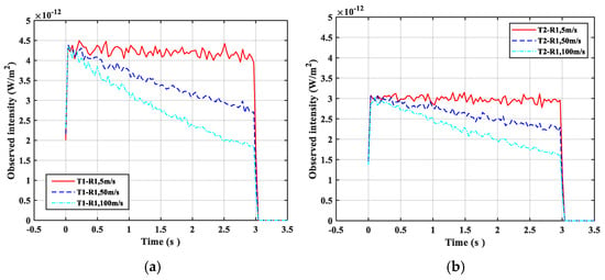
Figure 4.
Influence of moving speed on pulse response under fixed distance of parallel links: (a) pulse response signal of the T1–R1 link and (b) pulse response signal of the T2–R1 link.
As shown in Figure 4, with the fixed link space and increased moving speed of the receiver, the pulse response of both links steadily decreased. This phenomenon can be attributed to the decay of photon energy resulting from the increased transmission distance. We can see from Figure 4a that when the moving speed exceeds 50 m/s, the impulse response received by R1 decreases. Therefore, in the actual parallel link state of ultraviolet networking, the terminal moving speed cannot exceed 50 m/s; otherwise, the signal may not be received. Furthermore, upon comparing Figure 4a,b, we observe that the amplitude of decline in the impulse response of the T2–R1 link was slightly less pronounced compared with that of the T1–R1 link. This is because T2 and R1 are in a non-coplanar state, so the intensity of the impulse response is smaller and is less affected by the distance factor.
Subsequently, we examined the scenario in which the receiver moved toward the positive direction of the z-axis at speeds of 5 m/s, 50 m/s, and 100 m/s. R1 received the impulse response signals emitted from T1 and T2 as shown in Figure 5. When the moving speed of R1 was low, an increase in speed—such as from 5 m/s to 50 m/s—resulted in a continuous enhancement of the received impulse response signal, as shown in Figure 5a. Conversely, when the speed of R1 was high, such as at 100 m/s, the received impulse signal strength initially increased before rapidly diminishing. Based on the analysis, the decrease in moving speed caused the common scatter between receiver R1 and the transmitter to shift toward the receiver, thereby reducing the communication distance between them and increasing the strength of the received signal. Conversely, when the speed of R1 was high and it moved rapidly toward the positive z-axis direction, the common scattering diminished quickly, resulting in multiple scattering rather than single scattering. Thus, a phenomenon occurs where the impulse response signal first intensifies and then rapidly decreases. According to Figure 5b, the impulse response of the T2–R1 link diminished as the speed of movement increased. This decrease can be attributed to the absence of shared scatter between T2 and R1. As R1 swiftly moved in the positive z-axis direction, the photon’s trajectory lengthened owing to multiple scattering events. Consequently, the photon’s energy was gradually depleted, leading to rapid attenuation of the impulse response signal.
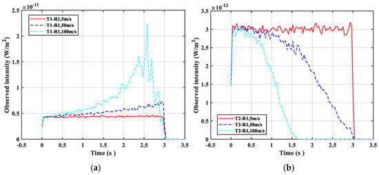
Figure 5.
Impulse response of different links when R1 moved along the z-axis at different speeds in parallel links. (a) Impulse response signal of T1–R1 link and (b) impulse response signal of T2–R1 link.
3.2. Effect of Node Movement Speed in Co-Addressed Link Scenarios
This section analyzes the impact of moving speed on the system impulse response in the scenario of transmitter co-addressed link and receiver co-addressed link. The moving speeds considered were 5, 30, 50, 70, and 100 m/s. Additionally, the impulse response of R1 was simulated when moving along the positive z-axis direction, which is at in the transmitter and receiver co-address link.
3.2.1. Transmitter Co-Addressed Link
A simulation of the impulse response of the T2–R1 link system, when the moving speed of the receiver was v = 5, 30, 50, 70, and 100 m/s in the transmitter co-addressed link scenario, is shown in Figure 6. It can be seen from the figure that as the moving speed increases, the intensity of the interference impulse signal received by the receiving end R1 continuously decreases.
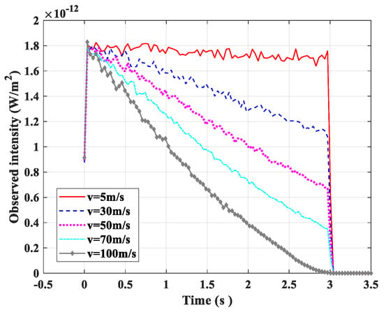
Figure 6.
Effect of receiver moving speed on impulse response of T2–R1 link when the receiver has a common node.
In the scenario of the sender co-addressed link, when the receiver moved forward along the z-axis at a speed of , the impulse response of R1 is shown in Figure 7. The impulse response of the T1–R1 link aligns with that shown in Figure 5a, whereas the impulse response of the T2–R1 link gradually increased and the impulse width decreased.
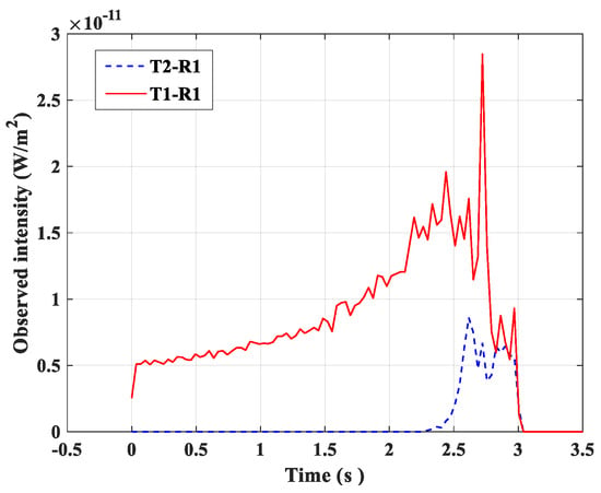
Figure 7.
Impulse response of different links under the transmitter with a common node, with movement along the z-axis direction.
This is because in the sender co-addressed link, R1 only received a minimal amount of backscattering from T2. Despite the small backscattering energy, as the receiver moved along the z-axis direction, photons emitted by T2 could easily reach R1 through multiple scattering, resulting in the appearance of a few impulses in the later stages.
3.2.2. Receiver Co-Addressed Link
In the receiver co-addressed link scenario, when the receiver moved at speeds of = 5, 30, 50, 70, and 100 m/s, the simulation results of the impulse response signal of the T2–R1 link system were consistent with those in Figure 6. As the speed increased, the impulse signal intensity received by T2–R1 decreased continuously.
Figure 8 shows the impulse response of R1 at a speed moved forward along the z-axis. Additionally, the impulse response of the T1–R1 link is consistent with that shown in Figure 5a. Owing to the increased photon transmission path in the T2–R1 link, the receiver energy decreases rapidly, resulting in decreased impulse response signal strength and narrow width.
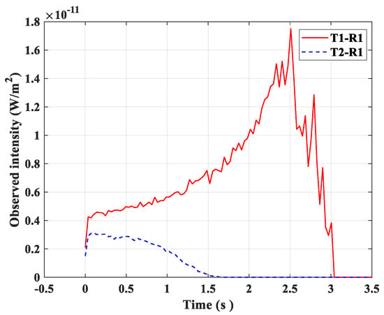
Figure 8.
Impulse response of different links when the receiver had a common node and moved along the z-axis.
3.3. Inter-Link Interference Problem
As shown in Figure 9, parallel links are simulated with varying link spacing : 10 m, 100 m, and 200 m. Notably, the intensity of the interference impulse response received by R1 from T2 varied with different link spacing. The interference signal strength gradually decreased with an increase in link space. The interference signal strength was almost negligible when the link space increased to 200 m. Therefore, in the actual parallel link state of ultraviolet networking, the link spacing cannot be less than 200 m; otherwise, the interference signal will be too large and a useful signal cannot be well obtained.
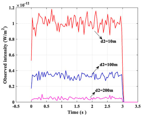
Figure 9.
Impulse response of links having different link spaces in T2–R1.
The pulse response that R1 received from T2 with different angles between links in the co-addressed scenario is shown in Figure 10. The interference signal received by R1 gradually decreased as the angle between the links increased, and when the angle between the links was acute, the signal width remained unchanged, the intensity decreased, and forward scattering was dominant when it reached R1 from T2, as shown in Figure 10a. Conversely, when the inter-link angle was obtuse, both the signal width and intensity decreased, with backward scattering prevailing in the signal path from T2 to R1. With an increase in the link angle, the motion path of the photon also increased, reducing the probability of the photon reaching the receiver through scattering. The situation in which the receiver was co-addressed is shown in Figure 10b, and from T2 to R1, forward scattering was dominant. Moreover, with an increase in the angle between links, the signal intensity received by R1 from T2 gradually decreased. Therefore, the larger the angle of , the less interference T2 causes to R1, which is more conducive to the acquisition of useful signals. Thus, in actual co-addressing link networking, the angle of should be greater than to better facilitate networking communication.
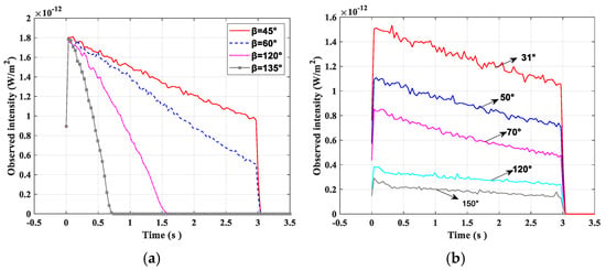
Figure 10.
Influence of the angle between links on T2–R1 impulse response in the co-address scenario. (a) Transmitter co-address and (b) receiver co-address.
4. Discussion
This study established the communication model of a wireless UV-light network based on MC, and it simulated and analyzed the link transmission characteristics in UV-light network communication. The study focused on the effects of the receiver moving speed, receiver and transmitter structural parameters, link space, and angle between links on the system impulse response in different link interference models. In the parallel link scenario, the interference impulse signal decreased continuously with an increase in the receiver’s moving speed under fixed link space conditions. When the receiver moved in the positive z-axis direction with different speeds, the intensity of the interference impulse response signal exhibited varying trends. In the transmitter co-addressed link scenario, the intensity of the received interference impulse decreased with an increase in the moving speed of the receiver. When the transmitter moved along the positive z-axis direction at 100 m/s, the interference impulse response signal gradually increased, whereas the impulse width decreased. Similarly, in the receiver co-addressed link scenario, the intensity of the received interference impulse decreased with an increase in the moving speed of the receiver. When the receiver moved in the positive z-axis direction at 100 m/s, the impulse response signal intensity decreased, whereas its width decreased. These findings highlight the significant fact that the receiver’s moving speed is the main factor affecting the interference impulse response. Furthermore, the impulse response intensity of interference signals is influenced by the link space distance in parallel links and by the angle between links in the transmitter and receiver co-addressed links.
Author Contributions
Conceptualization, C.L. and J.Y.; methodology, P.S. and J.Y.; software, X.Z. and J.Y.; formal analysis, X.Z.; writing—review and editing, C.L. and P.S. All authors have read and agreed to the published version of the manuscript.
Funding
This research was funded by the Science and technology plan project of Shaanxi Provincial Science and Technology Department, grant number 2024JC-YBQN-0678.
Data Availability Statement
The original contributions presented in this study are included in the article. Further inquiries can be directed to the corresponding author.
Conflicts of Interest
The authors declare no conflicts of interest.
References
- Zhao, T.F.; Ke, X.Z. Research on technologies in solar blind ultraviolet Ad hoc network. Appl. Res. Comput. 2010, 27, 2204–2207. [Google Scholar]
- Drost, R.J.; Sadler, B.M. Survey of ultraviolet non-line-of-sight communications. Semicond. Sci. Technol. 2014, 29, 084006. [Google Scholar] [CrossRef]
- Yuan, R.; Ma, J. Review of Ultraviolet Non-Line-of-Sight Communication. China Commun. 2016, 13, 63–75. [Google Scholar] [CrossRef]
- Ke, X.Z.; He, H.; Chen, X. A new backoff algorithm of MAC layer in UV ad hoc communication network. J. Optoelectron. Laser 2010, 21, 1002–1006. [Google Scholar]
- Li, J.B.; Wu, X.J.; Wang, H.X.; Li, B.F.; Liu, C.H. Anti-Interference Relayed Link Method and Power Requirement Analysis for Ultraviolet Non-Line-of-Sight Communication. Laser Optoelectron. Prog. 2015, 52, 030601. [Google Scholar]
- Pan, Y.; Long, F.; Li, P.; Shi, H.; Shi, J.; Xiao, H.; Gong, C.; Xu, Z. Beacon-Enabled TDMA Ultraviolet Communication Network System Design and Realization; IEEE: Piscataway, NJ, USA, 2023. [Google Scholar]
- Zhao, T.F.; Ma, Q.W.; Zhao, Y. Research on Performance of Wireless Ultraviolet Communication Interference Link. Laser Optoelectron. Prog. 2023, 60, 433–439. [Google Scholar]
- Cao, T.; Chen, S.; Wu, T.; Pan, C.; Song, J. Single-scatter channel impulse response model of non-line-of-sight ultraviolet communications. arXiv 2022, arXiv:2209.00992. [Google Scholar]
- Chen, G.; Xu, Z.; Sadler, B.M. Experimental demonstration of ultraviolet pulse broadening in short-range non-line-of-sight communication channels. Opt. Express 2010, 18, 10500–10509. [Google Scholar] [CrossRef] [PubMed]
- Luo, Y.X. Study on the Characteristics of Propagation of Ultraviolet Communication System and Voice Communication Platform Building; Shanghai Institute of Technical Physics Chinese Academy of Sciences: Shanghai, China, 2014. [Google Scholar]
- Qian, R.X.; Zhao, S.H.; Liu, Y. Influence of pulse broadening on bit error rate of ultraviolet communication. Laser Infr Ared. 2015, 45, 559–563. [Google Scholar]
- Wang, H.Q.; Wang, Y.G.; Cao, M.; Ke, X. Influence of Atmospheric Visibility on Laser Pulse Delay and Broadening in Sand and Dust Weather. Acta Opt. Sin. 2015, 35, 17–24. [Google Scholar] [CrossRef]
- Zhao, T.F.; Duan, Y.Z.; Li, X.S.; Gong, C. Effect of Soot Aggregates on Light Scattering in Ultraviolet Communication Channels. Acta Opt. Sin. 2020, 40, 213–221. [Google Scholar] [CrossRef]
- Wu, T.; Yang, F.; Song, J.; Ma, J.; Su, P. Modeling of UV diffused-LOS communication channel incorporating obstacle and its applicability analysis. Opt. Lett. 2021, 46, 4578–4581. [Google Scholar] [CrossRef] [PubMed]
- Luo, T.; Zuo, Y.; Li, F.; Du, Z.; Song, X.; Wang, Y.; Hong, X.; Wu, J. Omnidirectional path loss model for non-line-of-sight ultraviolet communications. Opt. Express 2024, 32, 15. [Google Scholar] [CrossRef] [PubMed]
- Song, P.; Ji, H.; Geng, X.; Zhang, G.; Zhang, L. On-channel characteristics of wireless ultraviolet communication with mobile terminals. Opt. Lett. 2022, 47, 929–932. [Google Scholar] [CrossRef] [PubMed]
- Su, C.X.; Song, P.; Meng, C. The pulse broadening ranging method of wireless ultraviolet optical communication. Xi’an Polytech. Univ. 2019, 32, 161–167. [Google Scholar]
- Ding, H.P.; Xu, Z.Y.; Sadler, B.M. A path loss model for non-line-of-sight ultraviolet multiple scattering channels. EURASIP J. Wirel. Commun. Netw. 2010, 2010, 598572. [Google Scholar] [CrossRef]
- Ding, H.; Chen, G.; Majumdar, A.K.; Sadler, B.M.; Xu, Z. Modeling of non-line-of-sight ultraviolet scattering channels for communication. IEEE J. Sel. Areas Commun. 2009, 27, 250. [Google Scholar] [CrossRef]
- Weisman, M.; Dagefu, F.T.; Moore, T.J.; Arslan, C.H.; Drost, R.J. Analysis of the Low-Probability-of-Detection Characteristics of Ultraviolet Communications. Opt. Express 2020, 28, 23640–23651. [Google Scholar] [CrossRef] [PubMed]
Disclaimer/Publisher’s Note: The statements, opinions and data contained in all publications are solely those of the individual author(s) and contributor(s) and not of MDPI and/or the editor(s). MDPI and/or the editor(s) disclaim responsibility for any injury to people or property resulting from any ideas, methods, instructions or products referred to in the content. |
© 2025 by the authors. Licensee MDPI, Basel, Switzerland. This article is an open access article distributed under the terms and conditions of the Creative Commons Attribution (CC BY) license (https://creativecommons.org/licenses/by/4.0/).