Abstract
Background: The need to improve gait emulation in people with amputation has driven the development of customized prosthetic mechanisms. This study focuses on the design and validation of a mechanism for external knee joint prostheses, based on the trajectory of the Instantaneous Center of Rotation (ICR) of a healthy knee. Objective: The objective is to design a mechanism that accurately reproduces the evolution of the ICR trajectory, thereby improving stability and reducing the user’s muscular effort. Methods: An exploratory methodology was employed, utilizing computer-aided design (CAD), kinematic simulations, and rapid prototyping through 3D printing. Multiple configurations of four- and six-bar mechanisms were evaluated to determine the ICR trajectory and compare it with a reference model obtained in the laboratory from a specific subject, using MATLAB-2023a and the Fréchet distance as an error metric. Results: The results indicated that the four-bar mechanism, with the incorporation of a simple gear train, achieved a more accurate emulation of the ICR trajectory, reaching a minimum error of 6.87 mm. Functional tests confirmed the effectiveness of the design in terms of stability and voluntary control during gait. It can be concluded that integrating the mechanism with the gear train significantly enhances its functionality, making it a viable alternative for the development of external knee prostheses for people with transfemoral amputation, based on the ICR of the contralateral leg.
1. Introduction
The loss of a lower limb, particularly at the transfemoral level, presents a major challenge for patients’ mobility and quality of life [1]. The biomechanics of the knee are essential for stable and efficient walking, and replacing its function with an external prosthesis remains both a technological and clinical challenge [2]. Currently, most commercially available knee prostheses have limitations in replicating natural gait, as they rely on standardized mechanisms that do not adapt to the anatomical and kinematic characteristics of each user [3,4,5,6].
The use of standard devices, such as knee prostheses, exoskeletons, and rehabilitation systems, introduces additional challenges when they are not properly aligned with the individual biomechanics of each patient [7]. Most of these devices are designed using generic measurements, forcing users to adapt their walking patterns and muscular effort to the mechanics imposed by the system, rather than having the device adapt to their needs [8,9,10,11,12]. This lack of customization, along with inadequate alignment and load distribution in prosthesis design, can lead to back pain, joint degeneration, postural compensations, excessive muscle fatigue, instability, and an increased risk of secondary injuries to the spine, hip, and residual lower limb [7,13,14]. Furthermore, the mismatch between the natural knee kinematics and the motion path of the standard prosthetic mechanisms can result in asymmetric gait patterns, reducing energy efficiency during walking and diminishing overall comfort for the user [15].
Several authors have emphasized the importance of a user-centered design to prevent discomfort and secondary injuries [16,17]. In an ideal approach, devices should be designed to match the user’s biomechanical structure, optimizing gait kinematics and reducing the effort required for adaptation. Additionally, such an approach would also enhance mobility, stability, and overall quality of life while minimizing the mechanical compensations that often result from using standard technologies.
Designing mechanisms based on the Instantaneous Center of Rotation (ICR) has proven to be a promising strategy to improve the functionality of knee prostheses, as it allows for more natural movement and reduces the patient’s muscular effort [3,7,18,19]. The trajectory of the ICR varies significantly depending on the dimensions and position of the joint. This individual variability of the ICR depending on the individual is a condition that makes the design process for this type of prosthesis complex [3]. Consequently, accurately replicating the ICR remains a challenge due to the limitations of current kinematic models and the complexity of adjusting the structural parameters of the mechanism [15].
Rapid prototyping using 3D printing has emerged as a key tool for optimizing medical devices, especially in the design of prostheses, exoskeletons, and rehabilitation systems [20]. Three-dimensional printing makes it possible to fabricate highly customized components that match each user’s morphology and biomechanics, overcoming the limitations of standard devices [3,21]. This technology enables rapid iteration among different designs, facilitating the testing of structural and functional variations and optimization of the mechanism’s kinematics before final production. It not only accelerates the development process but also reduces costs and improves the accuracy of natural movement emulation [3,7]. In the case of knee prostheses, rapid prototyping enables the evaluation and adjustment of the ICR trajectory, ensuring that the mechanism adapts to the user’s gait rather than imposing artificial mechanics that compromise mobility [15].
The combination of computer modeling, simulation, and additive manufacturing enables the creation of innovative solutions that enhance the integration between the user and the device, promoting greater functionality, comfort, and energy efficiency during walking.
2. Materials and Methods
2.1. Study Design
This study, based on the ICR, employed an exploratory research methodology that allowed for iterative adjustments to refine both the geometry and the functional behavior of the mechanism, as illustrated in Figure 1. The experimental validation was carried out with an able-bodied participant, aiming to ensure methodological control and safety during the initial phase of evaluation of the proposed models. This preliminary trial aimed to verify the mechanical integrity and kinematic behavior of the system under controlled laboratory conditions. This approach is consistent with previously conducted feasibility and human factors studies, allowing adjustments to the alignment, range of motion, and comfort features of the prosthetic mechanism.
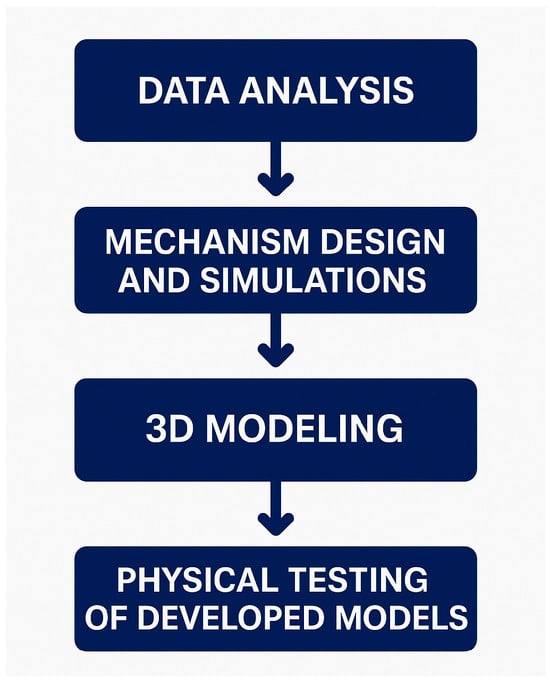
Figure 1.
Structure of the study.
2.1.1. Preliminary Data Analysis
In the laboratory gait trial involving a subject with no lower limb pathology, walking motion was recorded on a treadmill for at least eight continuous gait cycles. The data were then processed to obtain the ICR of the knee joint in the sagittal plane, as illustrated in Figure 2. Additionally, the mean values of the data were calculated to identify the behavioral trend of the trajectories, allowing for the selection of a reference curve for the present study.
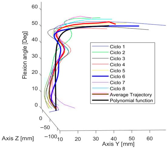
Figure 2.
Trajectories of the knee joint’s ICR in the sagittal plane across gait cycles.
Cycles 6, 7, and 8 were selected due to the continuity of their trajectories. After analyzing their behavior, the trajectory of cycle 6 was chosen, as shown in Figure 2, because it best matched the overall data trend and closely resembled the characteristic “J”-shaped pattern of the estimated ICR trajectory.
Out of the 70 functions evaluated, the one that provided the best fit with the lowest standard error was the rational regression model, with a standard error of 2.2367. This function, expressed in Equation (1), includes the following constants:
Once the motion coordinates were obtained, the trajectory was projected in the CAD (SolidWorks 2021–2022) software by positioning dimensioned points corresponding to the coordinates of the target curve derived from the mathematical model. Additionally, angular values were indicated as references for the knee joint flexion angle, as detailed in Figure 3.
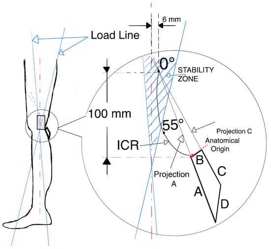
Figure 3.
Positioning of the target ICR curve and the four-bar mechanism.
2.1.2. Mechanism Design: CAD Modeling and Computational Simulation
Four-bar and six-bar mechanisms are among the most widely used in the design of prosthetic systems. In this study, the four-bar mechanism was selected due to the flexibility it offers in adjusting the dimensions and angles of its links. These modifications were performed iteratively, comparing in each configuration the trajectory of the anatomical ICR with that obtained from the mechanism. To quantify the degree of similarity, comparison metrics were applied, enabling the identification of the most suitable configuration.
To properly align the reference curve of the ICR with the links of the mechanism being designed, it is essential to define a set of quantitative design parameters.
2.1.3. Three-Dimensional Modeling
The links of the four-bar mechanism are shown alongside the reference ICR curve, positioned according to the specifications provided in Table 1 and Table 2. Link B is fixed, and the projection of links A and C generates the ICR during gait.

Table 1.
Positioning of the knee’s anatomical reference system.
Table 2.
Design considerations for the mechanism of an external knee prosthesis.

The origin of the ICR is located approximately 100 mm from the anatomical center of the knee and 6 mm posterior to the reference axis of the leg. To verify stability, load lines corresponding to heel contact and toe-off were drawn. As shown in Figure 3, the origin of the ICR is within the stability zone, thereby meeting the specifications for a voluntary control mechanism.
Once the mechanism is positioned and aligned with the leg, the iteration process continues with different link sizes until the desired trajectory is closely matched. The three most relevant models are presented below.
2.1.4. Model 1
The dimensions of the four links were adjusted until a configuration was achieved that generated a trajectory similar to the target ICR curve. Additionally, the angle between link B and the horizontal axis was modified. The corresponding dimensions are presented in Table 3 and illustrated in Figure 4.
Table 3.
Dimensions of Model 1.
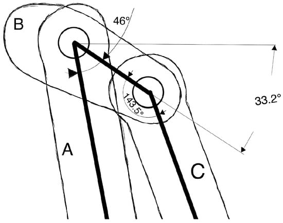
Figure 4.
Link B is fixed at an angle of 33.2° relative to the horizontal line.

The ICR trajectory in Model 1 exhibits a certain degree of similarity to the behavior of the target trajectory, although a greater overall length is observed. Furthermore, when analyzing the correlation between the angle indicated in the target ICR curve and the angle formed between the coupler and the anatomical axis of the leg, a 50° difference in flexion is identified.
2.1.5. Model 2
To adjust the generated ICR trajectory, several modifications were made to the four-bar mechanism regarding the position of the ICR origin and the stability zone, as shown in Figure 5.
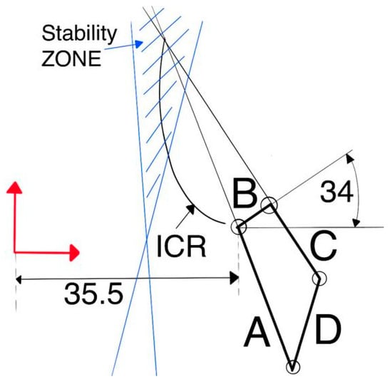
Figure 5.
Position of link B and overall mechanism positioning.
To ensure that the mechanism remains within the stability zone and that the curve aligns with reference dimensions, the vertical distance between the anatomical center of the knee and the ICR origin was reduced to 75.424 mm, while the horizontal distance was maintained at 6 mm relative to the anatomical axis, as shown in Figure 5. Another important detail is the position of link B, located 35.5 mm from the anatomical axis of the leg and oriented at an angle of 34° relative to the horizontal axis, as illustrated in Figure 5. Additionally, the model dimensions are presented in Table 4.
Table 4.
Dimensions of model 2.

2.1.6. Model 3
For Model 3, a kinematic chain with two degrees of freedom is proposed for knee movement: one controls the position of the ICR (red mechanism), while the other (blue mechanism) governs the flexion of the leg, as illustrated in Figure 6.
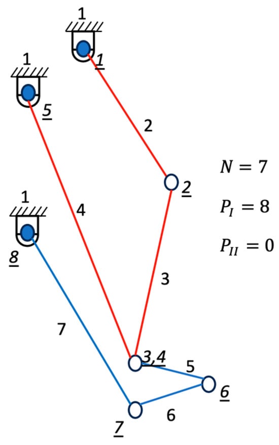
Figure 6.
Diagram of the two-degree-of-freedom mechanism of Model 3.
Through a computer program based on genetic algorithms [22], the synthesis of the ICR mechanism (red bars) was achieved. In addition, a secondary mechanism (blue bars) was developed to control the flexion angle (β). Subsequently, the angles of the RB (ε) and SD (α) bars with respect to the longitudinal axis of the sagittal plane were adjusted to align the position of the ICR generated by the mechanism with the flexion angle (β). Finally, the positional relationship (Rp) between the RB (ε) and SD (α) bars was obtained, as detailed in Table 5.
Table 5.
Obtained angles.
To minimize costs, the degrees of freedom of the kinematic chain were reduced from two to one by incorporating a simple gear train. For this purpose, the positional relationship was used as the transmission ratio (Rt), which was set at 0.93 in this study, as it satisfies the last two leg flexion angles. The results are presented in Table 6, and a schematic representation is shown in Figure 7.
Table 6.
Real and ideal angles.
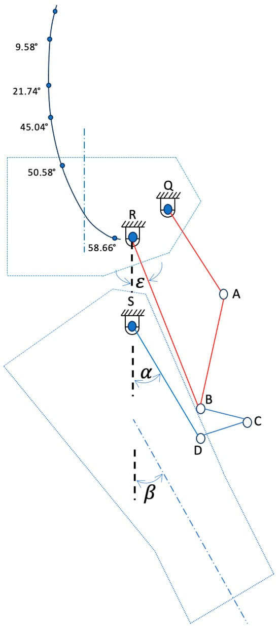
Figure 7.
Diagram of the two-degree-of-freedom mechanism in Model 3.
It can be observed that by setting Rt = 0.93, an average relative error of 0.094 is obtained between the ideal flexion angle (β [IDEAL]) and the actual flexion angle (β [REAL]), which validates the reduction in the degrees of freedom of the kinematic chain from two to one.
This model represents an improved version that preserves both the link dimensions and the interlink angles, differing only by the incorporation of gears with a transmission ratio of Rt = 0.93 and an enhanced aesthetic design. Moreover, this transmission ratio ensures a close approximation between the angular relationship of the leg axis and the ICR.
The incorporation of the gear train enabled a more accurate alignment. The Fréchet distance, with a value of 6.87 mm at Rt = 0.93, indicated the best match achieved after multiple iterations. From a biomechanical perspective, this configuration improves gait stability.
A simple gear train was implemented, consisting of one gear per shaft, configured so that the direction of rotation corresponds to the leg’s flexion movement. Additionally, an idler gear was included, which does not affect the transmission ratio Rt. The gear specifications are presented in Table 7 and illustrated in Figure 8. Furthermore, gear interference and contact ratio were verified, ensuring compliance with AGMA requirements.
Table 7.
Dimensions and positioning of the mechanism and gear train.
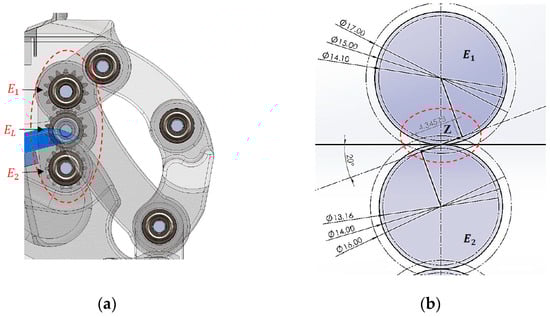
Figure 8.
Position of the gears, length of the line of action (z), and the physical verification that there is non-interference: (a) gear positioning and (b) line of action (z).

Mechanical motion constraints were incorporated into to Model 3 to prevent hyperextension and to limit flexion, with a maximum flexion angle of 60°, as shown in Figure 9.
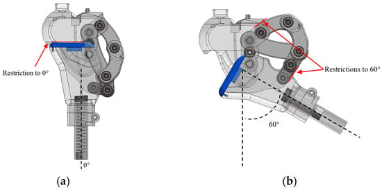
Figure 9.
Motion constraints: (a) maximum extension and (b) flexion limit.
This model also includes a flexible and replaceable component designed to fit into the coupler, which helps absorb impact during the stance phase of gait, as shown in Figure 7 (blue-colored element).
2.2. Participant
Models 1 and 3 were tested with an able-bodied participant, with no history of injuries, surgeries, or any pathologies that could affect normal gait. The participant was selected based on anthropometric parameters representative of an adult limb (height: 1.60 m; weight: 68 kg; knee range of motion between 0° and 60°). This choice was made with the aim of validating the developed device in a controlled context, free from pathologies that could interfere with natural gait, thereby avoiding compensations that could skew the measurements. In this way, the behaviors observed during the tests could be reliably attributed to the performance of the device rather than to clinical factors or gait alterations.
The testing protocol followed a meticulous approach, under the constant supervision of a medical specialist in prosthetics, who verified the correct placement and alignment of the device at each stage. The steps were as follows:
- Clinical evaluation:
It was verified that the participant had no prior injuries or surgeries that could alter their gait. The stump was adapted so that a non-amputee participant could use the external knee prosthesis and its components. Anthropometric measurements were also taken, and the target prosthetic length was established.
- Bench alignment:
The socket, Models 1 and 3 developed in this study, the tube, and the foot were assembled, with neutral foot rotation, and with minimum heights. This allowed for the establishment of a safe initial configuration for the tests.
- Static alignment:
With the participant standing between parallel bars, the heights were leveled, plantar support and the line of load were verified, and it was ensured that the center of mass remained within the base of support. The position of the socket, foot rotation, and stability in bipedal stance were reviewed, making fine adjustments in the sagittal and frontal planes to achieve a stable and comfortable posture without pain from pressure.
- Dynamic alignment:
During supervised walking, the phases of support, swing, and step-time symmetry were observed, and adjustments to the device’s alignment were made as needed.
- User education:
The participant was instructed on postural control, weight transfer, and walking between parallel bars, progressing to free walking with the device.
Once Models 1 and 3 were properly placed and aligned, the testing phase continued, where the participant walked on a flat surface of 7 m in length (round trip), with 5 min intervals between each repetition. This cycle was repeated between three and five times to allow the user to adapt to the device. When the participant showed mastery and control of the prosthesis, the trials for this study were recorded, without the use of parallel support bars.
Additionally, the study followed institutional ethical guidelines for non-clinical testing, and informed consent was obtained from the participant.
2.3. Functionality Tests
For the development of prototypes and the functionality tests, 3D printing based on fused deposition modeling (FDM) with PET-G material was employed for most of the components, using 100% infill during slicing. Additionally, standard elements such as 5 mm diameter bearings, shafts, and retaining rings were selected to complete the assembly. Figure 10 shows the prototypes ready to be tested with the same subject from whom the ICR trajectory was obtained.
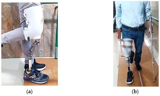
Figure 10.
Physical prototypes used in the functionality tests: (a) Model 1 and (b) Model 3.
Functionality tests were required on Models 1 and 3 presented in this study. For this purpose, an adapted socket was used to allow testing with the same subject from whom the target ICR was obtained. Controlled trials were carried out at the facilities of Fundación Prótesis Imbabura, with the support of specialized physiotherapists.
Model 1, shown in Figure 10a, enables functional walking, although it is not fully efficient. High energy expenditure was observed during gait, and certain limitations were identified. Due to the absence of a compression spring, greater effort is required to return the foot after the swing phase. Additionally, the coupler, located 66 mm posterior to the leg’s load line, compromises the user’s balance.
Model 3, shown in Figure 10b, successfully emulates the subject’s natural gait without limitations or difficulties. Its mechanism enables safe walking, maintaining balance, and voluntary control of movement. There is no gear interference, and the compression spring enhances comfort by automatically returning the foot after the swing phase. Additionally, the flexible damping component reduces load and impact on the residual limb during the return to the stance phase, improving movement efficiency and smoothness.
To verify the ICR trajectories of the main models, it can be observed that Model 3 exhibits the greatest similarity to the reference curve, as shown in Figure 11 and Table 8.
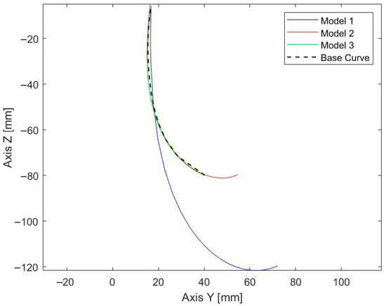
Figure 11.
ICR trajectories of the three main models along with the reference curve.
Table 8.
Discrete Fréchet distance between the main models and the target ICR trajectory.
The similarity between the trajectories was evaluated using the discrete Fréchet distance, with the results presented in Table 6. Among the analyzed models, Model 3 recorded the lowest value (6.87 mm), representing the closest correspondence to the reference curve. This finding was consistent with the root mean square error (RMSE), which reached 9.75 mm along the Y-axis and 31.17 mm along the Z-axis, with an overall RMSE in the YZ plane of 32.13 mm. Likewise, the mean Euclidean distance was 1.09 mm, while the maximum deviation did not exceed 45.36 mm. Complementary metrics confirmed this trend: the Hausdorff distance matched the Fréchet value (6.87 mm), the enclosed area between curves was 27.66 mm2, and the length variation with respect to the reference pattern was minimal (0.39 mm).
3. Results
Knee Joint Flexion During Gait
From a biomechanical perspective, the knee joint flexion angles were analyzed throughout the gait cycle. The results showed that the mechanism adjusted with Rt = 0.933 more accurately reproduced the flexion and extension peaks characteristic of the walking phases, closely approximating the kinematics of a healthy knee in both the stance and swing stages, as shown in Figure 12. This adjustment promotes a more natural movement, reduces undesirable residual displacements, and may improve load distribution on the residual limb, thereby decreasing the risk of high-pressure points and misalignment-related injuries.
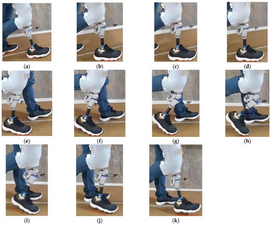
Figure 12.
Gait cycle during Model 3 walking: (a) initial contact 0%, (b) mid-stance 10%, (c) mid-stance 20%, (d) mid-stance 30%, (e) terminal stance 40%, (f) terminal stance 50%, (g) pre-swing 60%, (h) initial swing 70%, (i) mid-swing 80%, (j) terminal swing 90%, and (k) terminal swing 100%.
In terms of structural control, achieving a movement closer to the physiological pattern reduces external compensatory forces, thereby increasing dynamic stability and user comfort. Therefore, selecting a transmission ratio of Rt = 0.933 constitutes a viable geometric adjustment that directly links the mechanical design with the functional and biomechanical performance of gait.
The evaluation of Model 3 was conducted based on the leg flexion movement during gait. This movement is essential for maintaining cadence, balance, and proper posture. Figure 12 presents the flexion angles obtained during the gait cycle of Model 3. Furthermore, Figure 13 shows the similarity between the obtained curves and the gait pattern of a healthy leg, demonstrating proper functionality.
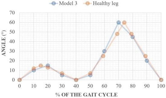
Figure 13.
Gait cycle of Model 3 during functionality tests.
Table 9 presents the results of the spatiotemporal metrics obtained during the gait analysis of a patient with a height of 1.60 m, compared with normative values reported for healthy adults. The energy expenditure was calculated using the ACSM metabolic equation for walking on level ground, which enables the estimation of oxygen consumption and the corresponding energy cost under controlled conditions.
Table 9.
Spatiotemporal metric by height and gender (males), patient with a height of 1.60 m.
The subject achieved a step length of 0.65 m while using the prosthesis, compared to 0.70 m recorded without it and the reference value of 0.72 m, indicating a slight reduction in the step pattern. Regarding cadence, a notable decrease was observed from 110 steps/min without the prosthesis to 80 steps/min with the prosthesis, compared with the reference value of 110 steps/min. This reduction suggests an adaptation of the gait pattern, possibly associated with increased stability and postural control demands required during the use of the prosthetic device.
The walking speed was 0.86 m/s with the prosthesis and 1.27 m/s without it, compared to the normative value of 1.32 m/s, indicating a 35% reduction relative to the physiological gait pattern. This finding is consistent with the literature, which reports that transfemoral prosthesis users tend to prioritize stability over speed during the initial adaptation phase.
In terms of energy expenditure, the specific metabolic cost was 0.0433 kcal·kg−1·min−1 with the prosthesis, compared to 0.0556 kcal·kg−1·min−1 without it, indicating a slight improvement in energy efficiency. However, the cost per distance was higher (0.839 kcal·kg−1·km−1 with the prosthesis versus 0.730 kcal·kg−1·km−1 without it), suggesting that although energy consumption per minute decreases, the relative effort per unit of distance traveled remains greater when using the prosthetic device, possibly due to the lower walking speed.
Overall, the results indicate that the patient achieves a functional gait with the prosthesis, albeit with lower cadence and walking speed compared to a healthy individual. This finding reflects an ongoing adaptation process in which safety and control are prioritized over energy optimization.
4. Discussion
The personalized prosthesis developed in this study demonstrates significant biomechanical improvements in reproducing the natural kinematics of the human knee. Commercial polycentric systems such as the Balance Knee™ and Cheetah Knee™ (Össur-Reykjavik, Iceland), analyzed by [3], exhibit Instantaneous Center of Rotation (ICR) trajectories that vary according to linkage geometry, directly influencing gait stability and energy efficiency. However, these standardized configurations cannot adapt to the individual biomechanical characteristics of each user, often leading to postural compensations and an increased metabolic cost.
In contrast, the prosthesis proposed in this work was designed based on the experimentally obtained ICR trajectory of a test subject, enabling a more accurate approximation of the physiological motion of the knee. The integration of a four-bar linkage mechanism with a simple gear train allowed fine control of the angular relationship between the links, aligning the generated trajectory with the individualized ICR curve. This configuration achieved a minimum point-to-point error of 6.87 mm, which is lower than the deviations reported for recent modular or hybrid designs (8–10 mm) described by [24], and comparable to the most precise academic prototypes reviewed by [25].
Model 3 showed the closest correspondence with the reference curve, with metrics indicating a high degree of similarity. The agreement between the Fréchet and Hausdorff distances confirms that the trajectory faithfully reproduces the proposed path, while the low mean Euclidean distance and minimal length variation reinforce its geometric precision. These characteristics, together with a smooth and continuous trajectory, contribute to a more natural gait emulation, as corroborated by the functional tests.
From a methodological standpoint, the workflow integrated MATLAB-based analysis, CAD modeling, and rapid prototyping via 3D printing enabled iterative comparisons of polycentric configurations until a suitable balance between trajectory fidelity and structural robustness was achieved.
Unlike high-cost microprocessor-controlled prostheses such as the C-Leg or Rheo Knee, which rely on active feedback to correct kinematic inaccuracies, the proposed design achieves high trajectory fidelity through passive mechanical optimization, ensuring lower energy consumption, reduced structural complexity, and greater economic accessibility. These characteristics position the developed device as a balanced and adaptable alternative that combines geometric precision, mechanical simplicity, and user-specific customization.
Current trends in modular and adaptive architectures reinforce the value of personalized, ICR-guided solutions [26]. Recent studies highlight modular designs validated through kinematic and structural analyses, as well as their potential integration with distal components such as ankle and foot assemblies [24,25,26,27]. In this context, hybrid devices that combine polycentric, ICR-based mechanisms with modular and scalable configurations could offer practical advantages in adaptability, maintenance, and patient-specific customization [28].
Despite these strengths, the main limitation of this study lies in its validation with a single participant, which restricts the generalizability of the results [24,28,29]. Future research should expand the cohort to include different age ranges, activity levels, and anthropometric profiles [30], and conduct gait evaluations under real world conditions such as level walking, stair ascent and descent, and slope negotiation to confirm clinical applicability [31,32]. Moreover, incorporating energy expenditure and muscle fatigue metrics would complement the kinematic analysis, providing a more comprehensive assessment of functional performance.
Finally, the scarcity of population-level studies defining representative knee ICR trajectories reveals a knowledge gap that this work begins to address [33,34]. The development of extensive comparative databases could enable the creation of semi-personalized prosthetic mechanisms tailored to patient subgroups, thereby promoting technology transfer and clinical adoption of solutions grounded in individual biomechanics.
5. Conclusions
The development of a four-bar mechanism with a simple gear train for external knee prostheses can improve aspects related to the natural kinematics of the human knee, owing to its close approximation to the anatomical ICR trajectory of the evaluated subject. The implementation of technologies such as modeling and prototyping, along with the functional adjustments made during the process, enables appropriate customization. Its operation, based on a gear-driven system, has allowed for a more accurate approximation of the ICR trajectory of a healthy knee, with minimal error compared to the reference model. These characteristics could offer significant benefits for the advancement of this line of research. The study aims to continue developing new iterations of the mechanism, incorporating more extensive testing to validate its impact across different patient profiles.
Author Contributions
Conceptualization, C.A. and F.V.; methodology, D.O. and H.S.; software, F.V.; validation, C.A., F.V. and B.G.; formal analysis, D.O.; investigation, C.A. and F.V.; resources, B.G.; data curation, F.V.; writing—original draft preparation, C.A. and F.V.; writing—review and editing, C.A., F.V., H.S. and B.G.; visualization, C.A. and F.V.; supervision, B.G.; project administration, F.V.; funding acquisition, H.S. All authors have read and agreed to the published version of the manuscript.
Funding
This research received no external funding.
Institutional Review Board Statement
The study was conducted in accordance with the Declaration of Helsinki, and approved by the Research of the Universidad Técnica del Norte, Faculty of Engeneering in Applied Sciences (UTN-CI-2024-180-R, 16 October 2024).
Informed Consent Statement
Informed consent was obtained from all subjects involved in the study.
Data Availability Statement
The raw data supporting the conclusions of this article will be made available by the authors on request.
Conflicts of Interest
The authors declare no conflict of interest.
Abbreviations
The following abbreviations are used in this manuscript:
| ICR | Instantaneous Center of Rotation |
| CAD | Computer-Aided Design |
References
- Dadkhan, B.; Valizadeh, S.; Mohammadi, E.; Hasssankhani, H. Psychosocial adjustment to Lower-limb amputation. HealthMED 2013, 7, 502. [Google Scholar]
- Andriacchi, T.P.; Stanwyck, T.S.; Galante, J.O. Knee Biomechanics and Total Knee Replacement. J. Arthroplast. 1986, 1, 211–219. [Google Scholar] [CrossRef]
- Grodzka, K.; Sajewicz, E.; Dziemianowicz, M. Chapter 5 Kinematic Analysis of Instantaneous Centre of Rotation of Prosthetic Knee Mechanisms. 2023. Available online: https://www.researchgate.net/publication/366878422 (accessed on 3 September 2025).
- Barbu, D.M. A total knee prosthesis CAD design. In Proceedings of the 2017 E-Health and Bioengineering Conference (EHB 2017), Sinaia, Romania, 22–24 June 2017; pp. 511–514. [Google Scholar]
- Sánchez, J.; Hernández, R.J.; Torres, J.E. The mechanical design of a transfemoral prosthesis using computational tools and design methodology. Ing. E Investig. 2012, 32, 14–18. [Google Scholar] [CrossRef]
- Andrysek, J.; Michelini, A.; Eshraghi, A.; Kheng, S.; Heang, T.; Thor, P. Gait Performance of Friction-Based Prosthetic Knee Joint Swing-Phase Controllers in Under-Resourced Settings. Prosthesis 2022, 4, 125–135. [Google Scholar] [CrossRef]
- Murabayashi, M.; Mitani, T.; Inoue, K. Development and Evaluation of a Passive Mechanism for a Transfemoral Prosthetic Knee That Prevents Falls during Running Stance. Prosthesis 2022, 4, 172–183. [Google Scholar] [CrossRef]
- Li, Z.; Han, Y.; Liu, C.; Xiu, H.; Wei, G.; Ren, L. Design, Manufacture, and Experimental Validation of a Hydraulic Semi-Active Knee Prosthesis. IEEE Trans. Neural Syst. Rehabil. Eng. 2023, 31, 1394–1404. [Google Scholar] [CrossRef]
- Minnoye, A.L.M.; Plettenburg, D.H. Design, fabrication, and preliminary results of a novel below knee prosthesis for snowboarding: A case report. Procedia Eng. 2010, 2, 3133–3141. [Google Scholar] [CrossRef]
- Zhang, Y.; Cao, W.; Yu, H.; Meng, Q.; Lv, J. A four-bar knee joint measurement walking system for prosthesis design. Technol. Health Care 2021, 29, 823–828. [Google Scholar] [CrossRef]
- Zhang, Y.; Wang, E.; Wang, M.; Liu, S.; Ge, W. biomimetics Design and Experimental Research of Knee Joint Prosthesis Based on Gait Acquisition Technology. Biomimetics 2021, 6, 28. [Google Scholar] [CrossRef]
- Salas Velázquez, P.A.; Vergara, M.; Provenzano, S. Prótesis de rodilla: Fundamentos teóricos y técnicas computacionales para su diseño Knee Prosthesis: Theoretical foundations and computational techniques applied to its design. Cienc. E Ing. 2021, 42. [Google Scholar]
- Hagberg, K.; Brånemark, R. Consequences of non-vascular trans-femoral amputation: A survey of quality of life, prosthetic use and problems. Prosthet. Orthot. Int. 2001, 25, 186–194. [Google Scholar] [CrossRef]
- Alluhydan, K.; Siddiqui, M.I.H.; Elkanani, H. Functionality and Comfort Design of Lower-Limb Prosthetics: A Review. J. Disabil. Res. 2023, 2, 10–23. [Google Scholar] [CrossRef]
- Qadir, M.U.; Asad, M.; Raza, S.M.; Masood, H.; Rabbani, M.S. Design, analysis, and development of low-cost state variable damping polycentric transfemoral prosthesis. Sensors 2024, 24, 255. [Google Scholar] [CrossRef]
- Nguyen, T.T.; Wang, B.; Alas, H.; Jones, Q.; Clark, C.; Lazar, S.; Malik, S.; Graham, J.; Talaat, Y.; Shin, C.; et al. Prosthesis Embodiment in Lower Extremity Limb Loss: A Narrative Review. Appl. Sci. 2025, 15, 4952. [Google Scholar] [CrossRef]
- Gasparutto, X.; Bonnefoy-Mazure, A.; Attias, M.; Turcot, K.; Armand, S.; Miozzari, H.H. Comprehensive analysis of total knee arthroplasty kinematics and functional recovery: Exploring full-body gait deviations in patients with knee osteoarthritis. PLoS ONE 2024, 19, e0314991. [Google Scholar] [CrossRef]
- Claessens, T. Finding the location of the instantaneous center of rotation using a particle image velocimetry algorithm. Am. J. Phys. 2017, 85, 185–192. [Google Scholar] [CrossRef]
- Koo, S.; Andriacchi, T.P. The knee joint center of rotation is predominantly on the lateral side during normal walking. J. Biomech. 2008, 41, 1269–1273. [Google Scholar] [CrossRef]
- Ahrendt, D.; Romero Karam, A. Development of a computer-aided engineering–supported process for the manufacturing of customized orthopaedic devices by three-dimensional printing onto textile surfaces. J. Eng. Fibers Fabr. 2020, 15, 1–11. [Google Scholar] [CrossRef]
- Alkhatib, F.; Cabibihan, J.J.; Mahdi, E. Data for benchmarking low-cost, 3D printed prosthetic hands. Data Brief 2019, 25, 104163. [Google Scholar] [CrossRef]
- Vera, P.; David, C. Programa Computacional Para El Diseño Del Mecanismo de la Articulación de Rodilla. Bachelor’s Thesis, Universidad Tecnica del Norte, Ibarra, Ecuador, 2024. Available online: https://repositorio.utn.edu.ec/handle/123456789/15458 (accessed on 3 September 2025).
- Mobbs, L.; Fernando, V.; Fonseka, R.D.; Natarajan, P.; Maharaj, M.; Mobbs, R.J. Normative Database of Spatiotemporal Gait Metrics Across Age Groups: An Observational Case–Control Study. Sensors 2025, 25, 581. [Google Scholar] [CrossRef]
- Sayat, A.; Nursultan, Z.; Yerkebulan, N.; Aidos, S.; Arman, U.; Gani, S.; Kassymbek, O.; Asset, N. Review and Comparative Analysis of Modern Knee Prostheses with Development of a Conceptual Design. Eng. Proc. 2025, 104, 80. [Google Scholar] [CrossRef]
- Liang, W.; Qian, Z.; Chen, W.; Song, H.; Cao, Y.; Wei, G.; Ren, L.; Wang, K.; Ren, L. Mechanisms and component design of prosthetic knees: A review from a biomechanical function perspective. Front. Bioeng. Biotechnol. 2022, 10, 950110. [Google Scholar] [CrossRef] [PubMed]
- Drăgoi, M.V.; Hadăr, A.; Goga, N.; Baciu, F.; Ștefan, A.; Grigore, L.Ș.; Gorgoteanu, D.; Molder, C.; Oncioiu, I. Contributions to the Dynamic Regime Behavior of a Bionic Leg Prosthesis. Biomimetics 2023, 8, 414. [Google Scholar] [CrossRef] [PubMed]
- Shrestha, P.L.; Thapa, B.; Sujatha, S. Scaling Mechanical Knee Joints for Pediatric Transfemoral Prostheses: Does a Linear Geometric Factor Work? Prosthesis 2025, 7, 72. [Google Scholar] [CrossRef]
- Berettoni, A.; Driessen, J.J.M.; Puliti, M.; Barresi, G.; De Benedictis, C.; Ferraresi, C.; Laffranchi, M. Human-Centered Design Trade-Offs for Semi-Powered Knee Prostheses: A Review. IEEE Trans. Med. Robot. Bionics 2025, 7, 429–442. [Google Scholar] [CrossRef]
- Kooiman, V.G.M.; van Staveren, E.S.; Leijendekkers, R.A.; Buurke, J.H.; Verdonschot, N.; Prinsen, E.C.; Weerdesteyn, V. Testing and evaluation of lower limb prosthesis prototypes in people with a transfemoral amputation: A scoping review on research protocols. J. Neuroeng. Rehabil. 2023, 20, 1. [Google Scholar] [CrossRef] [PubMed]
- Hunt, G.R.; Gabert, L.; Hansen, C.; Foreman, K.B.; Lenzi, T. Open dataset of kinetics, kinematics, and electromyography of above-knee amputees during stand-up and sit-down. Sci. Data 2025, 12, 433. [Google Scholar] [CrossRef]
- De Marchis, C.; Ranaldi, S.; Varrecchia, T.; Serrao, M.; Castiglia, S.F.; Tatarelli, A.; Ranavolo, A.; Draicchio, F.; Lacquaniti, F.; Conforto, S. Characterizing the Gait of People with Different Types of Amputation and Prosthetic Components Through Multimodal Measurements: A Methodological Perspective. Front. Rehabil. Sci. 2022, 3, 804746. [Google Scholar] [CrossRef]
- Manz, S.; Seifert, D.; Altenburg, B.; Schmalz, T.; Dosen, S.; Gonzalez-Vargas, J. Using embedded prosthesis sensors for clinical gait analyses in people with lower limb amputation: A feasibility study. Clin. Biomech. 2023, 106, 105988. [Google Scholar] [CrossRef]
- Rasheed, F.; Martin, S.; Tse, K.M. Design, Kinematics and Gait Analysis, of Prosthetic Knee Joints: A Systematic Review. Bioengineering 2023, 10, 773. [Google Scholar] [CrossRef]
- Jiang, J.; Chen, P.; Peng, J.; Qiao, X.; Zhu, F.; Zhong, J. Design and Optimization of Lower Limb Rehabilitation Exoskeleton with a Multiaxial Knee Joint. Biomimetics 2023, 8, 156. [Google Scholar] [CrossRef] [PubMed]
Disclaimer/Publisher’s Note: The statements, opinions and data contained in all publications are solely those of the individual author(s) and contributor(s) and not of MDPI and/or the editor(s). MDPI and/or the editor(s) disclaim responsibility for any injury to people or property resulting from any ideas, methods, instructions or products referred to in the content. |
© 2025 by the authors. Licensee MDPI, Basel, Switzerland. This article is an open access article distributed under the terms and conditions of the Creative Commons Attribution (CC BY) license (https://creativecommons.org/licenses/by/4.0/).