Abstract
Objectives: This in vitro study aimed to evaluate the effects of three framework orientation (FO) positions on an SLM building platform (Horizontal [H], Diagonal-45° [D45°], Diagonal-60° [D60°]) and two designs (with [B] or without [NB] stabilizing bars) on the fitting accuracy of digitally fabricated Co-Cr RPD frameworks. Materials and Methods: A custom RPD framework CAD was performed on a 3D-printed resin-model of an edentulous maxilla with three geometric tooth forms. A Co-Cr alloy was processed via SLM processing into 24 framework specimens, divided into three FO groups (n = 8: H, D45°, D60°) and two subgroups each (n = 4: B, NB). Qualitative/quantitative fit-evaluation was assessed using virtual framework-to-model seating and a custom digital protocol with GOM Inspect software (2018-Hotfix5, Rev.115656). Mean fitting distances were calculated from 220 equidistant points per specimen. Statistical comparisons were performed using ANOVA-on-ranks, Kruskal–Wallis multiple comparisons, and Bonferroni adjustment. Results: FO Sub-Group medians (Q1, Q3: 25% and 75% Quartiles) (mm) were: H/NB 0.150 (0.140, 0.164), H/B: 0.136 (0.121, 0.152), D45°/NB: 0.230 (0.219, 0.241), D45°/B: 0.144 (0.137, 0.154), D60°/NB:0.238 (0.232, 0.247), D60°/B: 0.171 (0.166,0.176). Pairwise comparisons indicated the following statistically significant (p < 0.05) FO Sub-Group differences: H/B-D45°/NB, H/B-D60°/NB, D45°/B-D45°/NB, D45°/B-D60°/NB, H/NB-D45°/NB, H/NB- D60°/NB. Conclusions: Horizontal orientation improved RPD fit accuracy regardless of bar presence. D45° accuracy is enhanced by stabilizing bars, while D60° accuracy is unaffected by bar addition.
1. Introduction
The field of Modern Restorative Dentistry has been significantly impacted by the advent of Computer-Aided Design and Computer-Aided Manufacturing (CAD-CAM) technology, which utilizes both additive methods (such as Selective Laser Melting, SLM) and subtractive processes (like hard and soft milling) for the production of dental prosthetic restorations [1,2]. While subtractive manufacturing techniques, such as milling, yield precise restorations, they also have notable limitations, including material waste, challenges in creating bulky/complex geometries, and tool wear. In contrast, additive manufacturing processes address these drawbacks by enabling the rapid production of intricate objects with minimal material waste and no tool wear [3]. Specifically, SLM technology, where a high-energy laser beam melts a cobalt–chromium (Co-Cr) alloy powder in a layer-by-layer pattern on a substrate plate, is a fully automated process, which is relatively cost-effective, results in less raw material loss, eliminates the need for tool replacement (unlike milling), and can create complex, freeform shapes with undercuts and curves (such as crowns) [4,5,6]. Therefore, this technology appears to be ideally suited for the production of removable partial dentures (RPDs) frameworks [3].
Numerous research teams have investigated the effectiveness of the SLM technique in producing dental prosthetic restorations from Co-Cr alloys [5,7,8,9]. In 2006, Williams et al. [7] first proposed the fabrication of a Co-Cr RPD framework by a fully digital SLM protocol. There is, however, a lack of comprehensive documentation on evaluating the SLM technique for manufacturing RPDs, particularly concerning the framework fit accuracy, while existing data on fitting accuracy can be perplexing. When comparing the SLM technique with the casting technique, researchers have determined that both methods are clinically acceptable. Nevertheless, some groups have reported that the casting technique offers better fitting accuracy [10,11,12], while others have found contradictory results [13,14]. This confusion may stem from variations in research methodologies among different researchers and the multitude of technical parameters that can variably influence the final conclusions [3,12,15,16,17].
SLM machine parameters (e.g., cabin atmosphere, layer deposit thickness, laser beam characteristics) [5,6], and the post-sintering annealing process affects the alloy microstructure, material properties and subsequent fitting accuracy [6,18]. Another crucial factor affecting these properties is the orientation of the object during the building process. The object’s orientation on the building platform plane, known as the “polar angle” (Φ), plays a significant role in achieving the desired microstructure and mechanical isotropy of the framework [19,20]. Different orientations during the layer-by-layer construction can result in structural and mechanical inconsistencies in complex objects like RPD frameworks with various functional parts (major and minor connectors, bars, clasps) that require specific properties [19,20,21,22,23]. A broad range of inclinations from 0° to 90° polar angles have been investigated in various alloy types (Co-Cr-based, Al-based, Fe-based) with contradictory results [16,19,21,22,24]. It is apparent that the SLM technique produces metal frameworks with an anisotropic structure, which is dependent on the framework orientation (FO). RPD frameworks are bulky and complex, so it is practically impossible to orientate them in an absolute vertical direction on the platform, even though this would optimize production speed and cost-efficiency since more frameworks can be printed at the same time [21]. Inclined orientations (45°, 60°) can still be more suitable in terms of productivity compared to horizontal (0°).
While components fabricated through the SLM method typically undergo a stress-relief annealing treatment to minimize deformation in prosthetic restorations, thereby improving their fit, the inclusion of stabilizing bars can also contribute to increased resistance to deformation. According to Hitzler et al. [20], it is essential to conduct the annealing process for the RPD framework to ensure its structural integrity before removing any stabilizing bars, a practice that is well-established in traditional casting methods. Regrettably, it has been observed that the order of operations—performing annealing first and then removing any stabilizing bars—might be overlooked in SLM frameworks due to the incorrect assumption that the supporters/building platform alone provides sufficient support [21,25].
The current in vitro study aims to evaluate the fit of SLM-fabricated Co-Cr RPD frameworks. The impact of RPD FO (Horizontal [H], Diagonal-45° [D45°], Diagonal-60° [D60°]) on the building platform and the presence or lack thereof of stabilizing bars (with [B] or without [NB] stabilizing bars) on the dimensional accuracy was examined. The null hypothesis posits that there are no differences in the RPD frameworks’ fit produced with or without stabilizing bars using various orientations on the SLM machine platform.
2. Materials and Methods
Initially, a single experimental prototype resin-model of an edentulous maxilla was digitized via a Trios-3 intraoral scanner (3Shape™A/S, Copenhagen, Denmark). Three 3D geometric form shapes imitating teeth were designed on the top of the residual ridge using Siemens NX 12.0.2 (Munich, Germany) software. One was placed on the midline immediately labially to the incisal papillae while the other two were placed in the area of the second molars bilaterally. An equilateral triangle was thus created (this can be summarized as step 1: design and 3D printing of the prototype model). A custom RPD framework was then designed on the digitized resin-model using the Dental System 2019 (3Shape A/S, Copenhagen, Denmark) software to serve as the experimental framework. Particular emphasis was placed on ensuring symmetry along the palatal midline, utilizing all the available tools of the design software. The thickness of the framework was set at 1.2 mm, while a peripheral finishing bevel of 0.5 mm width was created. An experimental standardized RPD with palatal plate and three occlusal rests was thus designed. An identical second framework was designed, and three stabilizing bars were added to support the section of the metal framework that simulates the rests. The bars were horizontally joined above the theoretical geometric center of the respective specimen (this can be summarized as step 2: design of the RPD frameworks (with [B] or without [NB] stabilizing bars). The specific thickness of 1.2 mm, which slightly exceeds the usual maximum thickness (1 mm) for a palatal plate, was chosen to ensure the necessary rigidity and to avoid deformation during removal from the printing platform, especially at the transition point from the plate to the part that mimics the occlusal rests. For this reason, stabilizing bars were also added at this point in order to determine whether they help strengthen the weak transition area from the plate to the rests, where corners are present and the width is dramatically reduced. This resulted in a simplified design compared to the complexity of an everyday RPD; however, this design allowed the investigation of the experimental objectives described above and supported the study’s results. The two experimental designs were then exported into STL files and twenty-four (24) specimens were fabricated using commercially available Co-Cr fine powder (Mediloy S-Co, Bego, Bremen, Germany) with a particle size of 10 to 45 μm and chemical composition of Co 63.9, Cr 24.7, W 5.4, Mo 5.0, and Si 1 wt. % (according to the manufacturer), in an SLM machine (TruPrint Series 1000, Trumpf, Ditzingen, Germany) (Table 1).

Table 1.
Description of the hardware, software, printing process, and manufacturer information of the metal 3D printer and materials used.
The RPD specimens were divided into three groups, depending on the orientation in which they were placed on the SLM machine-building platform (Figure 1). The three groups comprised specimens positioned horizontally (H, n = 8), at a 45-degree diagonal angle (D45°, n = 8), and at a 60-degree diagonal angle (D60°, n = 8) as permitted by the supporters on the building platform. Each of the above groups was divided into two subgroups (SG, n = 4) depending on whether it was designed with stabilizing bars (B) or without bars (NB). This resulted in a total of 6 specimen groups (H/B, H/NB, D45°/B, D45°/NB, D60°/B, D60°/NB) (this can be summarized as step 3: placement and orientation of the frameworks on the SLM platform).
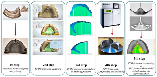
Figure 1.
Schematic flowchart of the experimental procedure. RPD (removable partial denture), SLM (selective laser melting).
SLM fabrication parameters were set as recommended by the manufacturer, i.e., scan speed: 500 mm/s, laser power: 90 W (Yb-fiber laser), beam diameter: 50 μm, and building layer thickness: 10 μm. Subsequently, the removable plate of the building/production platform with the RPD specimens was annealed in a special furnace (Preheating Furnace MV GLP7, Mihm Vogt, Germany) under argon atmosphere by inserting at 650 °C ramping (heating rate: 12.5 °C/min) to 800 °C and holding for 15 min (Table 1). Finally, the plate with the specimens was furnace-cooled to 550 °C (heating rate:~16 °C/min) (this can be summarized as step 4: fabrication via SLM and subsequent annealing). After the annealing procedure, the RPD specimens were removed from the furnace and allowed to naturally cool to room temperature. A band saw, a rotary cutter and pliers (suitable for dental materials) were used to remove the RPD specimens from the building platform and support structures. The removal of the frameworks from the platform was carefully performed by one of the authors (1b) in order to, as much as possible, avoid distortion of the frameworks. No post-processing procedures (e.g., polishing, finishing, or surface treatment) were performed prior to the fit-evaluation, in order to ensure that the results reflected the as-fabricated surface characteristics. The tissue surface of each metal framework was digitized via a Laboratory Scanner (E3, 3Shape™A/S, Copenhagen, Denmark) to create an STL file. A previously designed custom digital protocol that had been assessed for protocol and operator uncertainty as well as for scanning reproducibility was used for qualitative and quantitative model–framework fit-evaluation [26]. Approximately the same digital protocol was used by Rokhshad et al. [27]. In brief, the protocol entails sequential superimposition of each framework STL file to the digitized resin-model STL using a free inspection software (GOMInspect, 2018-Hotfix5, Rev.115656, GOM GmbH, Braunschweig, Germany) until a final virtual seating position is established. The latter is defined as the position where three non-colinear primary model–framework contacts are visually confirmed on the computer screen. The mean fitting distance between each of the framework/resin-model pairs is then calculated from 220 equidistant vertical framework-to-model measuring locations (this can be summarized as step 4: digitization of the frameworks for virtual fit-evaluation). All 6 group medians were then statistically compared (p = 0.05, ANOVA-on-ranks, Kruskall–Wallis multiple comparisons, Bonferroni adjustment) (IBM SPSS, Version:29.0.1.0 (171), USA. Figure 1 presents the sequence of all the experimental steps followed in this study.
The experimental procedure (methodology) described above can be summarized into five main steps. Figure 1 provides a schematic overview of these steps: (1) design and 3D printing of the prototype model, (2) design of the RPD frameworks (with [B] or without [NB] stabilizing bars), (3) placement and orientation of the frameworks on the SLM platform (Horizontal [H], Diagonal-45° [D45°], Diagonal-60° [D60°]), (4) fabrication via SLM and subsequent annealing, and (5) digitization of the frameworks for virtual fit-evaluation.
3. Results
Six groups of specimens were used in the present in vitro study, representing three orientations Horizontal [H], Diagonal-45° [D45°], Diagonal-60° [D60°]) and two different designs (with [B] or without [NB] stabilizing bars).
The results of the statistical analysis for the subgroup median framework-to-model distances are presented in Table 2. The observed fit accuracy values order was HB (0.136 mm), followed by D45°/B (0.144 mm), H/NB (0.150 mm), D60°/B (0.171 mm), D45°/NB (0.230 mm), and D60°/NB (0.238 mm). However, according to the performed pairwise comparisons, only the following statistically significant (p < 0.05) FO Sub-Group differences were found: H/B-D45°/NB, H/B-D60°/NB, D45°/B-D45°/NB, D45°/B-D60°/NB, H/NB-D45°/NB, H/NB- D60°/NB.
Table 2.
Results of the statistical analysis for the subgroup median framework-to-model distances.
The horizontal group (H) exhibited the best median fitting accuracy (smaller gap) among all groups, regardless of stabilizing bar existence. Also, in the diagonally oriented group (D45°), there was a significant (p < 0.05) improvement on the resultant fit (smaller gap) when using the stabilizing bar. The median gap distance was almost halved in this case (0.144 mm [B] vs. 0.230 mm [NB]). The presence of the bar in the other diagonally oriented group—D60°, was of no significant advantage (p > 0.05).
The qualitative analysis results of the virtual framework-to-model seating are presented in Figure 2 and Figure 3.
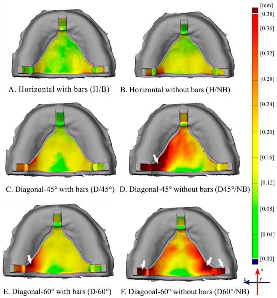
Figure 2.
Representative framework—model qualitative distance maps (first specimen from each subgroup). Colour-coded distance scale set from 0–0.38mm in all images to enable same-scale comparison across all subgroubs as indicated; Horizontal subgroups: (A) (H/B), (B) (H/NB); Diagonal-45° subgroups: (C) (D/45°), (D) (D45°/NB) and Diagonal-60° subgroups (E) (D/60°) and (F) (D60/NB°). White arrows indicate off-scale areas (i.e., distance exceeds 0.38mm).
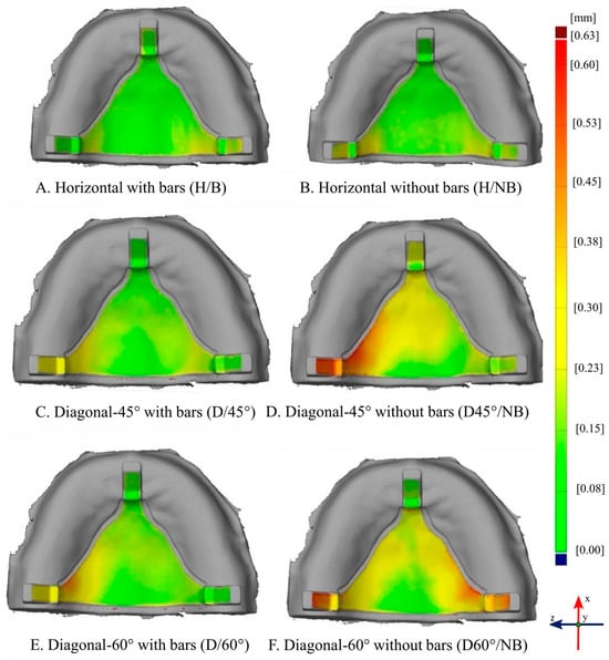
Figure 3.
Representative framework—model qualitative distance maps (first specimen from each subgroup). Colour-coded distance scale set from 0–0.63mm in all images to enable same-scale comparison across all subgroubs as indicated; Horizontal subgroups: (A) (H/B), (B) (H/NB); Diagonal-45° subgroups: (C) (D/45°), (D) (D45°/NB) and Diagonal-60° subgroups (E) (D/60°) and (F) (D60/NB°). This setting enables visual quantitative characterization confirmation as to the ranking of global fit across the entire framework tissue surface. Localised comparison is also possible here, with smaller deviations being less obvious in comparison to the setting in Figure 2.
Figure 2 shows some representative framework-to-model qualitative seating distance maps (first specimen from each subgroup presented). The color-coded distance scale has been set from 0 to 0.38 mm in all images to enable same-scale comparison across all subgroups. White arrows indicate off-scale areas where the distance exceeds 0.38 mm. The locality of the variations across different groups, however, becomes quite obvious in this setting. Figure 3 depicts the same samples; however, here, the color-coded distance scale has been set from 0 to 0.63 mm. This setting is applied in order to visually complement and underpin the quantitative characterization as to the ranking of global fit across the entire framework tissue surface. Localized comparison is also possible here; however, smaller deviations become less obvious in comparison to the color scale setting applied in Figure 2.
According to Figure 2, the deformations that the framework specimens appear to exhibit, seem to be more pronounced as we move from specimens with horizontal (H) to specimens with Diagonal-45° (D45°) and, even more, to those with Diagonal-60° (D60°) orientation. Perhaps less clearly but still visible, this also seems to hold true when moving from specimens with bars to those without bars.
4. Discussion
According to the results of this study, the null hypothesis was rejected since mixed quantitative results showed statistically significant differences in specific subgroup comparisons.
Our study reveals that the combination of horizontal RPD FO with or without stabilizing bars, along with the Diagonal-45° with bars (D45°/B) configuration, yielded the most accurate fit results among all tested options. Regarding the Diagonal-60° platform orientation, the presence of stabilizing bars led to better results, but without significant differences. In a recent systematic review and meta-analysis [28], researchers compared the fit accuracy of removable partial dentures (RPDs) fabricated using digital and conventional techniques. The study found that the mean gap size for RPDs created digitally was 140 μm, whereas the mean gap size for those fabricated using conventional methods was 164 μm. Notably, our own results for specific sample types, including HB, D45°/B, and H/NB, closely mirrored these values.
From a clinical perspective, it is essential to recognize how the orientation of the framework affects the physico-mechanical properties and fatigue life of RPDs, since these characteristics play a vital role in determining the mechanical performance/behavior of the prosthesis amid the dynamically changing environment of the oral cavity.
In their study, Takaichi et al. [16] sought to investigate the mechanical anisotropy of Co-Cr specimens produced through SLM. They constructed dumbbell-shaped specimens oriented at angles of 0°, 45°, and 90° relative to the building direction, which corresponds to the tensile direction. To determine the 0.2% offset yield strength and elongation (from the stress–strain curves), uniaxial tensile tests were conducted. Their findings indicated that the specimens at 45° and 90° exhibited greater 0.2% offset yield strength and reduced elongation, highlighting the anisotropic nature of their mechanical properties. Nevertheless, these measurements still met the type 5 standards set by ISO 22764 [29]. Additional research teams investigated the significance of the annealing process, a type of heat-treatment, on the mechanical properties of the final product while considering different orientations. In their in vitro research, Hitzler et al. [20] aimed to assess the microstructure and mechanical properties of Co–Cr–Mo produced using DMLS across various inclinations (0°, 30°, 60°, and 90°) in both as-built (AB) and heat-treated (HT) states. Their findings indicated that for all orientations examined (0–90°), there was a significant enhancement in tensile properties (including Young’s modulus, yield strength, elongation at failure, and ultimate tensile strength), along with increased hardness values after a brief and cost-effective heat-treatment cycle at 800 °C for 20 min of the Co–Cr–Mo alloys. To simulate the actual loading conditions of RPD components, Kajima et al. [22] conducted a study on the mechanical properties and fatigue strength of Co–Cr–Mo clasps. Co–Cr–Mo alloy specimens for both tensile (dumbbell) and fatigue tests (clasp specimens) were fabricated using SLM with varying angles between the building and longitudinal directions (0°, 45°, and 90°). Their results showed that the specimens oriented at 45° and 90° demonstrated higher 0.2% offset yield strength and ultimate tensile strength, along with decreased elongation. In terms of fatigue strength, the clasp specimens at 90° exhibited a significantly longer fatigue life of 205.418 cycles, compared to 28.484 cycles for the 0° clasp specimens and 43.465 cycles for the 45° clasp specimens. This variation in fatigue performance was attributed to several factors, including crystal orientation, residual stress, surface roughness, and the boundaries of the molten pool. The fitting accuracy of RPDs was investigated by Hwang et al. [21]. Their findings revealed that vertically oriented RPD frameworks had a significantly poorer fit compared to those oriented horizontally, a result that this study corroborates with. They provided an intriguing explanation for this difference, noting that the horizontally oriented frameworks had 254 supports, whereas the vertically oriented ones had only 193. This disparity resulted in the vertically oriented frameworks having fewer heat sink channels, which means that internal heat stress could only dissipate through a limited number of pathways. Consequently, the deformation observed in the vertically oriented specimens was more pronounced. The researchers also emphasized that the interconnection of supports is an essential factor in achieving improved fitting accuracy, indirectly confirming the need for stabilizing bars used in this study.
The in vitro studies mentioned [20,22] earlier indicate that the 45° and 90° orientations demonstrate higher mechanical property values, exceeding the minimum acceptable standards established by ISO 22674 [29]. Notably, the findings from Kajima et al. [22] favor the 90° orientation, as it showed a significantly extended fatigue life of 205.418 cycles for the clasp specimens (following the 45° and 0°). Additionally, the results from Hitzler et al. [20] emphasize the importance of the annealing process, highlighting that the mechanical property values are directly influenced by the particular heat-treatment applied. While the aforementioned results initially support the 90° orientation, followed by the 45° orientation, the findings from Hwang et al. [21], regarding the fitting accuracy of RPDs, call into question the suitability of the 90° orientation.
Although the previously mentioned studies indicate that 90° and 45° orientations (of dumbbell specimens) yield optimal mechanical properties and fatigue strength [16,22], the current in vitro research did not assess the 90° orientation. Instead, it concentrated on Horizontal, Diagonal-45°, and Diagonal-60° orientations. This decision was made for two reasons: firstly, obtaining a fully vertical (90°) orientation on the platform is virtually impossible for RPD frameworks, even though it could improve production speed and cost efficiency; secondly, it considers the earlier findings from Hwang et al. [21]. Throughout the production of the RPD frameworks, the implemented procedure adhered to both manufacturer guidelines and findings from other in vitro studies. Specifically, the annealing process was conducted (regardless of orientation), followed by the removal of supports after annealing [20]. As illustrated in Figure 2, the H/NB subgroup appears to exhibit poorer palatal adaptation compared to the H/B subgroup, with more intense “yellow” areas indicating greater local deviations, whereas the H/B shows more uniform “green” areas suggestive of better adaptation. Although the quantitative measurements did not reveal a statistically significant difference (p > 0.05) between the H/B and H/NB subgroups (Table 2), the qualitative assessment highlights localized discrepancies that are visually apparent but may be masked when data are averaged over the entire surface. This discrepancy between the two approaches reflects the inherent limitation of quantitative analyses based solely on mean deviation values, which can obscure small but clinically relevant variations in specific regions of the framework. Therefore, integrating both qualitative and quantitative evaluations provides a more comprehensive understanding of adaptation accuracy. The complementary use of numerical deviation data alongside topographical mapping, as employed in the present study, allows for the detection of subtle, region-specific deviations that could have potential clinical implications for fit and patient comfort. In the case of D45°, while exhibiting the second direction described earlier, the bar presence effect becomes significant in the quantitative comparisons (p < 0.05) while also complemented by the qualitative images (Figure 2). The effect, although again insignificant for the D60°, still manifests itself in the qualitative evaluation.
Another interesting finding in the present study, which was provided by the qualitative evaluation, was the observed variation across deformation patterns and their dependency upon FO. Increasing deformation across specimen groups also appears to occur towards a specific direction, i.e., along the axis defined by the sagittal plane (median palatine suture). This increase, however, appears to manifest itself in opposite directions when comparing horizontally (H), to diagonally-45° (D45°) and diagonally-60° (D60°) placed specimens: In the horizontally placed specimen group (H), in the specimens without bars subgroup (H/NB), it seems that the posterior retainers deform by “bending” towards the tissue surface—and thus, the palate does not appear to fit as well as it seems to fit in the specimens with bars (H/B). This can be seen by observing that the retainer areas have more and deeper green appearance than the palate surface in the respective groups (Figure 2).
In the D45° and D60° placed specimen groups, for specimen subgroups without bars, (D45°/NB, and D60°/NB) it seems that the posterior retainers deform by bending more in the opposite direction, i.e., away from the tissue. This means that, when attempting to seat the framework to the model, the palate and the anterior retainer tissue surfaces will fit first while the posterior ones will not come in contact. This is quite apparent in Figure 2 (where more off-scale areas are closer to the posterior retainers) but also in Figure 3 where more yellowish and reddish areas appear in the posterior retainer segments. These results corroborate the general agreement in the literature that the major gap is under the major connector independently of the type of the framework [11,12,14,30]. Salim et al. [31] studied the fit of the major connector without clasps and seats, finding that there was a gap in the major connector but in a clinically acceptable range. The framework was processed in 30° inclination.
According to the authors’ knowledge, there is no other study yet that has investigated the different deformation pattern in relation to the FO on the building platform.
Regarding the evaluation method, a number of experimental protocols have been used in the past to evaluate RPD’s fitting accuracy, i.e., the gap between major connectors, rest seats, clasps and the hard and soft tissues [3,11,12,21,23,30,31]. The “replica method”, where a disclosing media (polyvinylsiloxane material) is used, is one of the oldest and probably the most common. This manual method, however, can be highly dependent on the investigator’s experience, due to the inherent incapability for inter-investigator standardization. Recently, digital methods using STL data analysis with digital superimposition and color mapping that may overcome the technique sensitivity of the manual methods have been proposed [11,21,23,32,33]. In this study, a previously developed custom digital protocol was utilized providing a multitude (220) of equidistant measurement datums for the gap between the RPD framework and the master model, enabling both qualitative and quantitative analysis. According to Theocharopoulos et al. [26], the applied protocol provided considerable confidence for the reliability of our measurements as (a) in terms of scanning reproducibility, all mean values within the designated framework area gave almost identical findings with other studies [21,34,35] and (b) in terms of the actual framework-to-model distances and the potentially introduced uncertainties due to protocol and operator, all mean values recorded gave equally similar findings to other studies.
Another interesting feature is the post-treatment handling. In contrast to a study of Rokhshad et al. [27], where the intaglio surface of the frameworks was also treated by aluminum oxide airborne particle abrasion and tungsten carbide milling cutters, in our study, the fit was studied without treatment of the tissue surface in order to investigate the fitting accuracy without any attempt for improvement.
Currently, all RPD manufacturing techniques (e.g., casting, 3D-printing) would still require a manual seating stage which includes selective grinding of small areas by a trained dental technician until the best possible fit can be achieved on a working model. This study measures the accuracy of fit in as-manufactured frameworks, post-heat treatment but before manual seating, finishing and polishing. That means the accuracy of the applied methodology (equipment and technique parameters) was measured avoiding the subjectivity of a post-manufacturing human intervention. The mean gap discrepancy measured (in absolute mean values), however, is generally in agreement with other studies (Soltanzadeh et al.: 0.33 ± 0.2 mm [11], Hwang et al.: 0.167 mm [21], Arnold et al.: 0.365 ± mm [14], Chen et al.: 0.25 ± 0.01 mm [30], Muehleman et al.: 0.428 to 0.325 mm [12]), who collectively concluded that these values are within the clinically acceptable range.
In a similar study, ref. [27] found slightly smaller differences (Mean; 109 ± 21 mm, Max.; 115 ± 6 mm) compared to ours, which can be attributed to the different methodology and the finishing treatment of the intaglio surface of the frameworks.
Korkes A et al. [36] studied the fit of digitally and conventionally fabricated RPD frameworks on the abutment teeth on a Kennedy class III modification 1 partially edentulous mandibular arch. So, the major connector’s fit was not evaluated as the lingual bar selected in their study was fabricated with clearance from the soft tissue. They found closer adaptation of retentive and reciprocating arms for the SLM frameworks in comparison to the conventionally fabricated frameworks. So, they confirmed previous findings [14] that the incremental fabrication of the framework pattern on the platform of SLM machine means that the framework is produced with minimal processing-related strains, which subsequently leads to greater dimensional stability. They concluded that, as the difference among the groups was less than 0.02 mm, it is likely that this difference is not of clinical significance, and that partial denture SLM frameworks have a promising seating accuracy in comparison to conventional frameworks.
Unfortunately, at present, there is no clearly established clinically acceptable value, ISO standard or specification in the international literature that defines the clinically acceptable gap between an RPD and the oral tissues, as is the case, for example, with the marginal adaptation of metallic or ceramic crowns according to the American Dental Association (ADA) Specification No. 8 [37]. The only available reference, based on several in vitro and in vivo studies as well as literature reviews, suggests that a gap from 0 to 50 µm is considered no gap, while a gap from 50 to 311 µm is regarded as a clinically acceptable fit [7,11,16,19]. Therefore, we can conclude that the findings of the present study fall within the range of clinically acceptable values.
The limitations of this study include its in vitro nature, which prevents direct comparison with the oral environment, where factors such as tooth mobility, soft tissue resilience and thickness, type of edentulism, and occlusal load could influence/alter the fit of the frameworks in vivo. Future clinical validation studies are therefore warranted to confirm these findings in vivo and provide a more balanced perspective on their applicability. A study model of maxillary RPD was studied, but it is of clinical importance to also study a mandibular model. Finally, another limitation of this study is that only one commercially available Co-Cr alloy was used, as well as the recommended settings of the SLM device and a specific annealing process. It is possible that a different combination of alloy/SLM device settings/annealing process’ parameters could have produced different fitting results.
In general, it seems that SLM fabrication methods for RPD frameworks can achieve satisfactory fitting accuracy. The results of this study (HB > D45°/B > H/NB > D60°/B > D45°/NB > D60°/B, Table 2) align with prior research, which indicates that frameworks constructed in a horizontal orientation generally provide improved fitting accuracy [21]. However, it is important to note that horizontal orientation comes with certain drawbacks. Notably, (1) the mechanical property values marginally meet the minimum requirements set by ISO 22674 [16,20,22,29], and (2) the fatigue life is significantly shorter at 28,484 cycles compared to the 90° and 45° orientations, which last 205,418 and 43,465 cycles, respectively [22]. Considering the points mentioned above and the insignificant (p > 0.05 difference in median fitting accuracy between the Horizontal-0° and Diagonal-45° orientations, the rationale for prioritizing D45°/B in regular clinical practice appears promising in terms of building platform capacity optimization.
Although the present study is an in vitro investigation, its results are significant for the anticipated clinical performance of RPDs, as digital technologies such as digital scanning [38] and CAD-CAM workflows [39] provide reliable precision not only for single crowns but also for more extensive prosthetic restorations, such as removable partial dentures and others. So, according to the above, the frameworks that were produced with the aid of CAD/CAM technology fell within clinically acceptable values, which agrees with previously mentioned studies [11,12,14,21,28,30,31,36].
5. Conclusions
Under the limitations of this in vitro study, it can be concluded that FO during the SLM process plays an important role in the fit accuracy of RPDs. Frameworks produced in a horizontal orientation (with or without stabilizing bars), as well as those fabricated in a Diagonal 45° orientation with bars (D45°/B), exhibited significantly better fit accuracy compared to all other orientations tested, which may be important from a production efficiency perspective. The combination of a Diagonal 60° platform orientation with stabilizing bars showed no effect on the fit accuracy of the RPD frameworks. Overall, the fitting accuracy of the produced frameworks was within clinically acceptable limits.
Author Contributions
All authors participated equally in all stages of the study. A.L.T. performed the software methods. All authors have read and agreed to the published version of the manuscript.
Funding
This research received no external funding.
Institutional Review Board Statement
Not applicable.
Informed Consent Statement
Not applicable.
Data Availability Statement
The original data presented in the study are openly available in https://doi.org/10.5281/zenodo.14604055.
Acknowledgments
The authors are deeply indebted to the Dental Laboratory “Laboratory 86” (Nafsikas 12 str., P. Faliro, Athens, Greece) for designing and producing the examined Co-Cr specimens for the needs of the present study.
Conflicts of Interest
The authors declare no conflicts of interest.
References
- van Noort, R. The future of dental devices is digital. Dent. Mater. 2012, 28, 3–12. [Google Scholar] [CrossRef]
- Wang, G.; Wang, S.; Dong, X.; Zhang, Y.; Shen, W. Recent progress in additive manufacturing of ceramic dental restorations. J. Mater. Res. Technol. 2023, 26, 1028–1049. [Google Scholar] [CrossRef]
- Akl, M.A.; Stendahl, C.G. Removable Partial Denture Frameworks in the Age of Digital Dentistry: A Review of the Literature. Prosthesis 2022, 4, 184–201. [Google Scholar] [CrossRef]
- Al Jabbari, Y.S. Physico-mechanical properties and prosthodontic applications of Co-Cr dental alloys: A review of the literature. J. Adv. Prosthodont. 2014, 6, 138–145. [Google Scholar] [CrossRef] [PubMed]
- Koutsoukis, T.; Zinelis, S.; Eliades, G.; Al-Wazzan, K.; Rifaiy, M.A.; Al Jabbari, Y.S. Selective Laser Melting Technique of Co-Cr Dental Alloys: A Review of Structure and Properties and Comparative Analysis with Other Available Techniques. J. Prosthodont. 2015, 24, 303–312. [Google Scholar] [CrossRef]
- Dimitriadis, K.; Foteinidis, G.; Kosarli, M.; Moschovas, D.; Paipetis, A.S.; Agathopoulos, S. Microstructure and Mechanical Properties of Co-Cr Alloy Fabricated by Selective Laser Melting Technology for Removable Partial Denture Frameworks. J. Mater. Eng. Perform. 2022, 32, 8637–8646. [Google Scholar] [CrossRef]
- Williams, R.J.; Bibb, R.; Eggbeer, D.; Collis, J. Use of CAD/CAM technology to fabricate a removable partial denture framework. J. Prosthet. Dent. 2006, 96, 96–99. [Google Scholar] [CrossRef]
- Al Jabbari, Y.S.; Barmpagadaki, X.; Psarris, I.; Zinelis, S. Microstructural, mechanical, ionic release and tarnish resistance characterization of porcelain fused to metal Co-Cr alloys manufactured via casting and three different CAD/CAM techniques. J. Prosthodont. Res. 2019, 63, 150–156. [Google Scholar] [CrossRef]
- Revilla-Leon, M.; Gomez-Polo, M.; Park, S.H.; Barmak, A.B.; Ozcan, M. Adhesion of veneering porcelain to cobalt-chromium dental alloys processed with casting, milling, and additive manufacturing methods: A systematic review and meta-analysis. J. Prosthet. Dent. 2022, 128, 575–588. [Google Scholar] [CrossRef]
- Ye, H.; Ning, J.; Li, M.; Niu, L.; Yang, J.; Sun, Y.; Zhou, Y. Preliminary Clinical Application of Removable Partial Denture Frameworks Fabricated Using Computer-Aided Design and Rapid Prototyping Techniques. Int. J. Prosthodont. 2017, 30, 348–353. [Google Scholar] [CrossRef]
- Soltanzadeh, P.; Suprono, M.S.; Kattadiyil, M.T.; Goodacre, C.; Gregorius, W. An In Vitro Investigation of Accuracy and Fit of Conventional and CAD/CAM Removable Partial Denture Frameworks. J. Prosthodont. 2019, 28, 547–555. [Google Scholar] [CrossRef]
- Muehlemann, E.; Ozcan, M. Accuracy of Removable Partial Denture Frameworks Fabricated Using Conventional and Digital Technologies. Eur. J. Prosthodont. Restor. Dent. 2022, 30, 76–86. [Google Scholar] [CrossRef]
- Tregerman, I.; Renne, W.; Kelly, A.; Wilson, D. Evaluation of removable partial denture frameworks fabricated using 3 different techniques. J. Prosthet. Dent. 2019, 122, 390–395. [Google Scholar] [CrossRef]
- Arnold, C.; Hey, J.; Schweyen, R.; Setz, J.M. Accuracy of CAD-CAM-fabricated removable partial dentures. J. Prosthet. Dent. 2018, 119, 586–592. [Google Scholar] [CrossRef]
- Zaeh, M.F.; Branner, G. Investigations on residual stresses and deformations in selective laser melting. Prod. Eng. 2009, 4, 35–45. [Google Scholar] [CrossRef]
- Takaichi, A.; Suyalatu; Nakamoto, T.; Joko, N.; Nomura, N.; Tsutsumi, Y.; Migita, S.; Doi, H.; Kurosu, S.; Chiba, A.; et al. Microstructures and mechanical properties of Co-29Cr-6Mo alloy fabricated by selective laser melting process for dental applications. J. Mech. Behav. Biomed. Mater. 2013, 21, 67–76. [Google Scholar] [CrossRef]
- Suzuki, Y.; Shimizu, S.; Waki, T.; Shimpo, H.; Ohkubo, C. Laboratory efficiency of additive manufacturing for removable denture frameworks: A literature-based review. Dent. Mater. J. 2021, 40, 265–271. [Google Scholar] [CrossRef]
- Yan, X.; Lin, H.; Wu, Y.; Bai, W. Effect of two heat treatments on mechanical properties of selective-laser-melted Co-Cr metal-ceramic alloys for application in thin removable partial dentures. J. Prosthet. Dent. 2018, 119, 1028.e1–1028.e6. [Google Scholar] [CrossRef] [PubMed]
- Hitzler, L.; Janousch, C.; Schanz, J.; Merkel, M.; Heine, B.; Mack, F.; Hall, W.; Öchsner, A. Direction and location dependency of selective laser melted AlSi10Mg specimens. J. Mater. Process. Technol. 2017, 243, 48–61. [Google Scholar] [CrossRef]
- Hitzler, L.; Alifui-Segbaya, F.; Williams, P.; Heine, B.; Heitzmann, M.; Hall, W.; Merkel, M.; Öchsner, A.; Yao, Z. Additive Manufacturing of Cobalt-Based Dental Alloys: Analysis of Microstructure and Physicomechanical Properties. Adv. Mater. Sci. Eng. 2018, 2018, 8213023. [Google Scholar] [CrossRef]
- Hwang, S.; An, S.; Robles, U.; Rumpf, R.C. Process parameter optimization for removable partial denture frameworks manufactured by selective laser melting. J. Prosthet. Dent. 2023, 129, 191–198. [Google Scholar] [CrossRef]
- Kajima, Y.; Takaichi, A.; Nakamoto, T.; Kimura, T.; Yogo, Y.; Ashida, M.; Doi, H.; Nomura, N.; Takahashi, H.; Hanawa, T.; et al. Fatigue strength of Co-Cr-Mo alloy clasps prepared by selective laser melting. J. Mech. Behav. Biomed. Mater. 2016, 59, 446–458. [Google Scholar] [CrossRef] [PubMed]
- Tasaka, A.; Shimizu, T.; Kato, Y.; Okano, H.; Ida, Y.; Higuchi, S.; Yamashita, S. Accuracy of removable partial denture framework fabricated by casting with a 3D printed pattern and selective laser sintering. J. Prosthodont. Res. 2020, 64, 224–230. [Google Scholar] [CrossRef] [PubMed]
- Xie, W.; Zheng, M.; Wang, J.; Li, X. The effect of build orientation on the microstructure and properties of selective laser melting Ti-6Al-4V for removable partial denture clasps. J. Prosthet. Dent. 2020, 123, 163–172. [Google Scholar] [CrossRef] [PubMed]
- Gowri, V.; Patil, N.P.; Nadiger, R.K.; Guttal, S.S. Effect of anchorage on the accuracy of fit in removable partial denture framework. J. Prosthodont. 2010, 19, 387–390. [Google Scholar] [CrossRef]
- Theocharopoulos, A.; Vergos, V.; Dimitriadis, K.; Caroni, C.; Yannikakis, S. A Digital Protocol for Qualitative and Quantitative RPD Fit Analysis. In Proceedings of the 2023 Continental European and Scandinavian Divisions Meetings, Rhodes, Greece, 2–5 September 2023. [Google Scholar]
- Rokhshad, R.; Tehrani, A.M.; Nahidi, R.; Zarbakhsh, A. Fit of removable partial denture frameworks fabricated from 3D printed patterns versus the conventional method: An in vitro comparison. J. Prosthet. Dent. 2024, 131, 1144–1149. [Google Scholar] [CrossRef]
- Naka, O.; Kamalakidis, S.N.; Anastassiadou, V. The Impact of Current Fabrication Methods on the Fit Accuracy of Removable Partial Dentures: A Systematic Review and Meta-Analysis. Appl. Sci. 2024, 14, 11034. [Google Scholar] [CrossRef]
- ISO:22674; Dentistry-Metallic Materials for Fixed and Removable Restorations and Appliances. International Organization for Standardization: Geneva, Switzerland, 2016.
- Chen, H.; Li, H.; Zhao, Y.; Zhang, X.; Wang, Y.; Lyu, P. Adaptation of removable partial denture frameworks fabricated by selective laser melting. J. Prosthet. Dent. 2019, 122, 316–324. [Google Scholar] [CrossRef]
- Salim, S.; Salleh, N.M.; Abidin, Z.Z.; Yunus, N.; Rahmat, R.; Ibrahim, N. Physicomechanical properties of cobalt-chromium removable partial denture palatal major connectors fabricated by selective laser melting. J. Prosthet. Dent. 2022, 128, 530.e1–530.e7. [Google Scholar] [CrossRef]
- Oh, K.C.; Yun, B.S.; Kim, J.H. Accuracy of metal 3D printed frameworks for removable partial dentures evaluated by digital superimposition. Dent. Mater. 2022, 38, 309–317. [Google Scholar] [CrossRef]
- Ciocca, L.; Maltauro, M.; Pierantozzi, E.; Breschi, L.; Montanari, A.; Anderlucci, L.; Meneghello, R. Evaluation of trueness and precision of removable partial denture metal frameworks manufactured with digital technology and different materials. J. Adv. Prosthodont. 2023, 15, 55–62. [Google Scholar] [CrossRef] [PubMed]
- Michelinakis, G.; Apostolakis, D.; Tsagarakis, A.; Kourakis, G.; Pavlakis, E. A comparison of accuracy of 3 intraoral scanners: A single-blinded in vitro study. J. Prosthet. Dent. 2020, 124, 581–588. [Google Scholar] [CrossRef] [PubMed]
- Ahmed, N.; Abbasi, M.S.; Haider, S.; Ahmed, N.; Habib, S.R.; Altamash, S.; Zafar, M.S.; Alam, M.K. Fit Accuracy of Removable Partial Denture Frameworks Fabricated with CAD/CAM, Rapid Prototyping, and Conventional Techniques: A Systematic Review. Biomed. Res. Int. 2021, 2021, 3194433. [Google Scholar] [CrossRef] [PubMed]
- Korkes, A.; Jomaa, J.; Kavouris, A.; Lalani, T.; King, P.; Lee, S.; Li, H.; Li, A.; Khuu, W.; Law, K.H.J.; et al. Seating accuracy of removable partial denture frameworks fabricated by different digital workflows in comparison to conventional workflow. J. Prosthodont. 2024; Online ahead of print. [Google Scholar] [CrossRef]
- Nikolopoulos, M.; Dimitriadis, K.; Yannikakis, S.; Sfikas, A.K.; Galiatsatos, A.; Tsolka, P. Implant-cemented Co-Cr frameworks produced by hard and soft milling: The impact of porcelain firing cycles on microstructure and fit accuracy. Eur. J. Oral Sci. 2025, 133, e70031. [Google Scholar] [CrossRef]
- Menchini-Fabris, G.B.; Cosola, S.; Toti, P.; Hwan Hwang, M.; Crespi, R.; Covani, U. Immediate Implant and Customized Healing Abutment for a Periodontally Compromised Socket: 1-Year Follow-Up Retrospective Evaluation. J. Clin. Med. 2023, 12, 2783. [Google Scholar] [CrossRef]
- Zhao, K.; Wu, S.; Qian, C.; Sun, J. Suitability and Trueness of the Removable Partial Denture Framework Fabricating by Polyether Ether Ketone with CAD-CAM Technology. Polymers 2024, 16, 1119. [Google Scholar] [CrossRef]
Disclaimer/Publisher’s Note: The statements, opinions and data contained in all publications are solely those of the individual author(s) and contributor(s) and not of MDPI and/or the editor(s). MDPI and/or the editor(s) disclaim responsibility for any injury to people or property resulting from any ideas, methods, instructions or products referred to in the content. |
© 2025 by the authors. Licensee MDPI, Basel, Switzerland. This article is an open access article distributed under the terms and conditions of the Creative Commons Attribution (CC BY) license (https://creativecommons.org/licenses/by/4.0/).