Abstract
The working parts of soil cultivation and sowing machines operate under conditions of intense abrasive wear. As wear on the working parts increases, the relative unevenness of their travel depth increases, leading to higher traction resistance and, consequently, higher specific fuel consumption. It has been established that the intensity of changes in the mass, wear volume, and geometric characteristics of working parts is determined by the combined influence of the treated area and the soil’s mechanical and physical properties, leading to differences in the service life before reaching the critical wear threshold. Studies based on scientific articles have shown that modern strengthening methods can significantly increase the service life of agricultural machinery working parts by 1.5 to 5 times. There are various methods for restoring and strengthening working parts, increasing their wear resistance and durability. New materials are used to increase the service life of working parts; they are hardened during manufacture and, during operation, restored and made more wear-resistant. This research aims to increase the wear resistance of the coulter anchor for seed and fertilizer application by welding a T-620 electrode to its working surface. The following steps were taken to achieve this goal: theoretical research, calculations, the verification of the results using computer modeling (Rocky DEM 2024 R1.1 software package) to predict the abrasive wear of hard surfaces, as well as laboratory and field tests to confirm the results of the theoretical and experimental scientific research.
1. Introduction
The working parts of soil cultivation, planting, and sowing machines are subject to intense abrasive wear [1,2,3,4,5,6,7]. The durability of working parts is largely determined by their service life. As wear increases, the relative unevenness of the working parts’ depth of travel increases, as does the machine’s traction resistance and, accordingly, fuel consumption. At all stages of field testing, the anchor wears out and the set working depth constantly changes. Depending on the area treated (ha) and the soil type, wear rates in terms of the mass and geometric shape vary [1,8,9]. The wear of many parts can reach 2–3 mm and, in some cases, lead to the deformation of the shape [10].
The working parts most susceptible to abrasive wear in soil cultivation and sowing machines are the plowshare in a plow; the sweep in a cultivator; the discs or teeth in a harrow; and the coulters in a seeder. The main reason for their premature failure is accelerated abrasive wear due to interactions with hard soil particles (HV 8–11 GPa) [1].
Depending on the soil type, moisture can either increase or decrease wear. Taken together, these factors have such a strong impact on the working parts of agricultural machinery that they become unusable after just a few hours of intensive operation [1,2].
In this regard, it should be noted that the sharply continental climate of Northern Kazakhstan has formed specific soil conditions. The main types of soil are ordinary and southern chernozems, loamy and medium loamy in mechanical composition, prone to salinization, and requiring special farming methods, where the developed coulter with an anchor for a wide-cut seeder was applied. When interacting in such an environment, anchors are more intensively subjected to abrasive wear, which leads to a change in their geometry, loss of sharpness, and a decrease in the quality of processing.
In addition, the working parts of agricultural machinery operate in a chemically aggressive environment, which is associated with the application of various fertilizers to the soil and the presence of moisture [3]. The soil moisture significantly affects the wear of parts of the soil cultivation machines that are in direct contact with abrasive masses [1,3].
At the same time, the technical condition of the blade of the working body of agricultural machinery primarily determines such performance indicators as the degree of weed cutting, the average depth of cultivation, the stability of the working bodies in terms of depth, their clogging and sticking to the blade surface, and the traction resistance of the working bodies [1,11].
A chamfer forms on the blade and the tip edge, negatively affecting the stability of the working bodies in terms of depth, altering the tip’s profile, geometry, and blade width of the working body (Figure 1). Blunt cultivator sweeps and plow shares increase the unit’s traction resistance, which significantly reduces their productivity, while fuel consumption increases by 15–20% [1,11].
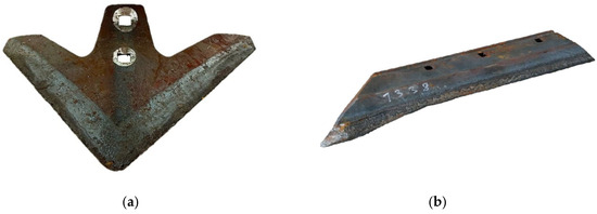
Figure 1.
Worn working parts of soil cultivation machines: (a) cultivator blade, (b) ploughshare.
The anchor is a new structural element of the coulter, for which a strengthening technology has not yet been selected. Therefore, it is important to study its wear process and select strengthening technologies during manufacturing in order to increase the wear resistance. A patent for inventions (No. 36760) of the Republic of Kazakhstan has been obtained for this coulter [12].
Due to the uneven wear of the cutting edges and other surfaces of the working parts of agricultural machinery, it is necessary to strengthen them during manufacture or restore them after wear.
The cutting edges of the working parts lose efficiency due to abrasive wear and require restoration. There are various methods for restoring and hardening working parts, increasing their wear resistance and durability. The following methods are used to increase the service life:
- The use of new materials;
- Hardening during manufacture;
- Methods for restoring and increasing wear resistance [9].
Research based on scientific articles has shown that modern strengthening methods can increase significantly the service life of agricultural machinery working parts by 1.5 to 5 times. The results of a comparative analysis of technologies for strengthening the working parts of agricultural machinery are presented in Table 1.

Table 1.
Comparative analysis of technologies for strengthening working parts of agricultural machinery.
A comparative analysis shows that when strengthening and restoring the working parts of agricultural machinery operating under conditions of intense abrasive wear, the key criteria are the cost ratio, resource growth, and technological flexibility. High-energy spraying methods and combined coatings provide a significant increase in the wear resistance, but their high cost and low maintainability significantly limit their practical application in serial operation.
Against this background, surfacing with wear-resistant electrodes is the most rational solution, as it combines a sufficient high increase in resources (up to 2.5–3 times), the possibility of the local strengthening of the most loaded areas, and the restoration of the part’s geometry at moderate production costs. In particular, the use of the T-620/E10-UM60-GP electrode [27] ensures the formation of a highly hard surfaced layer (≈790–800 HV), which resists the effectively abrasive and abrasive-impact wear of anchors and similar components.
The differences between basic and hardened anchors with a T-620 electrode coating are that the interaction of an unhardened anchor with hard and wet soil causes working surface destruction and abrasion. In high-humidity conditions, the adhesion strength decreases, and hard soil creates increased mechanical loads, causing the wear, deformation, and rupture of the material, making the structure fragile.
Surfacing with T-620 electrodes is intended for parts operating under predominantly abrasive wear conditions with moderate impact loads. This metal restoration technique is used in various industries, including mechanical engineering, agriculture, shipbuilding, aircraft construction, and instrument making, and helps to increase the service life of worn parts several times over. The rod is made of carbon steel and the coating contains ferrotitanium, chromium, boron, and other chemical components [28].
Thus, the choice of the T-620/E10-UM60-GP surfacing electrode is technically and economically justified, since this hardening method in the manufacture of coulter anchors provides an optimal balance between the part’s durability, process productivity, and costs, making it promising for practical applications and further engineering research.
In this work, theoretical studies were conducted to increase the wear resistance of the coulter anchor for applying seeds and fertilizers at various specified depths. Computer modeling capabilities were used to verify the results of the theoretical studies, in particular, the Rocky DEM (Discrete Element Method) program, which predicts the abrasive wear of hard surfaces based on Archard’s law [29,30].
This study aims to increase the wear resistance of the coulter anchor for seed and fertilizer applications by welding a T-620 electrode onto its working surface. It is necessary to conduct theoretical research, calculations, and verification of the results obtained using computer modeling (Rocky DEM software package) to achieve this goal, as well as laboratory and field tests to confirm the results of the theoretical and experimental scientific research.
2. Materials and Methods
The research methods are based on theoretical studies, calculations, and justification of the proposed method for increasing the wear resistance of the working body, performed using classical laws of agricultural and applied mechanics, computer modeling, and confirmed by experimental results. The initial samples for strengthening were coulter anchors for variable-depth seed and fertilizer application.
The coulter is installed on a wide-cut seeder [31] and is designed for use in the widely used traditional technology of grain cultivation in northern Kazakhstan. Figure 2 shows a coulter for applying seeds and fertilizers at various specified depths.
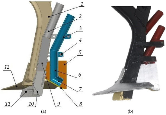
Figure 2.
Coulter for applying seeds and fertilizer granules at different specified levels: (a) 3D model of coulter, (b) experimental model of a coulter: 1. Stand; 2,9. Fertilizer pipes; 3,6,7. Seed pipe; 4. Support arm; 5. Side plates; 8. Plate; 10. Guide; 11. Anchor; 12. Arrow paw.
When the coulter is lowered, anchor 11, located below the sweep, cuts a furrow in the soil with a width equal to the thickness of the rack 1 to a specified depth for laying mineral fertilizer granules, while the arrow-shaped coulter 12 opens the furrow for seed placement, cuts weeds, and loosens the soil.
Mineral fertilizers are delivered to the bottom of the furrow through fertilizer pipes 2 and 9 and guide 10. The fertilizer is covered with a moist layer of soil due to the flow around anchor 11 and to its natural settling from the furrow walls.
The inclined plate 8 compacts the soil and prepares the seedbed for laying the seed material 3–4 cm above the fertilizer. Through the seed tube 3, 6, 7, and further into the guide—8—the seeds of grain crops are placed at the bottom of the furrow above the mineral fertilizers, which are then covered with moist soil due to the natural falling of soil from the furrow walls.
After the coulter passes, the soil is compacted with a roller. Anchor 11 and side plates 5 are replaceable elements that can be replaced when worn out.
During the technological process, the coulter anchor is subject to abrasive wear. In this regard, we identify in advance the working surfaces of the anchor most susceptible to wear and, using discrete element modeling (Rocky DEM program) [30], which allows us to predict abrasive wear of hard surfaces, strengthen them at the manufacturing stage.
Twenty-six coulter anchor samples are installed on a wide-cut seeder. For theoretical research to determine the hardness of the working surface of the anchor, 10 samples are selected at random. Of these, five samples are coated with a wear-resistant layer of T-620 electrode and then ground to their original shape, while the remaining five remain in their basic form.
The T-620/E10-UM60-GP (C 3.2%; Mn 1.2%; Si 2.2%; Cr 23.0%; Ti 1.3%; B 1.4%) is used to strengthen the anchor. Surfacing with these electrodes is used in parts operating under predominantly abrasive wear conditions with moderate impact loads [27].
The T-620 electrode surfacing technology involves direct current reverse polarity surfacing in a horizontal or inclined position (I, 190–220 A). The wear-resistant layer was deposited in 2–3 layers. The thickness of one layer was 1.5–2.0 mm, and the total thickness of the deposit was 3–5 mm. Welding was performed with reverse polarity direct current at a deposition rate of 8–12 m/h with a short arc length of 2–3 mm. The parts were preheated to 200–250 °C, maintaining the interlayer temperature within 180–250 °C to reduce residual stresses. Cooling was carried out in air without additional heat treatment. Its hardness can reach 60–62 HRC (790–800 HV).
High-elasticity and high-strength 65G steel is used for the anchor workpiece, which is used to manufacture most of the working parts of agricultural machinery. The hardness of 65G steel varies depending on its condition (30–49 HRC, 290–512 HV) [31]. Figure 3 shows samples of the anchor. The hardening process of the anchor sample is shown in Figure 4.
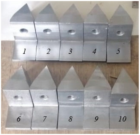
Figure 3.
Prototype coulter anchor samples.
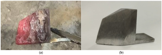
Figure 4.
Anchor sample hardening process: (a) after welding, (b) after grinding.
After grinding is complete, the working surface hardness of each sample is measured at twenty different points and its mass is recorded. The hardness tester and laboratory scales are used to determine the anchor’s hardness and mass.
Hardness measurements were performed on the cross-section of the welded layer in its central part, at a distance of at least 1.5–2 diameters from each other and from the fusion boundary. For each sample, 5–7 measurements were performed, followed by determination of the mean value and standard deviation (±15–25 HV). The statistical significance of the differences was assessed using Student’s t-test at a significance level of p = 0.05. Before measurements, the samples were ground and polished to a roughness of Ra ≤ 0.8 μm.
The hardness was measured using a MET-U1A (MET, Physical and Mechanical Measurements Center LLC, Moscow, Russia) ultrasonic hardness tester (Figure 5), a portable device consisting of an electronic unit and a sensor connected by a cable. The modification of the electronic unit for the MET-U1A hardness tester is made in an aluminum, dust- and moisture-proof housing with IP66 protection class.
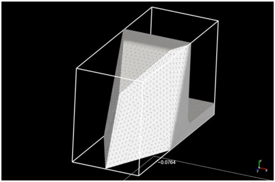
Figure 5.
Approximated triangular anchor grid of the coulter.
The material hardness is determined by the UCI (Ultrasonic Contact Impedance) method, not optically, as is customary in classical methods.
In this case, the hardness is determined electronically by measuring the change in ultrasonic frequency. The UCI sensor is based on a steel rod with a Vickers diamond pyramid (angle between faces 136°), which serves as an acoustic resonator for a built-in ultrasonic frequency generator. When the pyramid is inserted into the product being tested under the action of a fixed force from a calibrated spring, the resonator’s natural frequency changes, which is determined by the material hardness. The relative change in the resonator frequency is converted by an electronic unit into a hardness value on the selected scale and displayed on the screen [32].
CAS MW-II (CAS Corporation, Seoul, Republic of Korea) laboratory scales were used to obtain more accurate mass measurements for the anchor samples. This scale model is designed for accurate weighing in various fields of science and technology. The scales belong to a line of analytical equipment with a fairly high measurement accuracy. The manufacturer of the model is CAS, a recognized leader in the development and production of various weighing equipment [33]. The data obtained are entered into Table 2.
Table 2.
Hardness and mass indices of anchor samples.
Based on the measurement results, the minimum average Vickers hardness of the base samples is 335.8, the maximum is 348.5, and the average is 344.2. Accordingly, the minimum average hardness value of the hardened samples is 774.85, the maximum is 828.95, and the average is 792.51. The hardness of the working surface of the anchor sample increased from 2.3 to 2.5 times. All measurement results will be used in theoretical calculations to determine the volume and mass of wear.
Archard’s law was used to perform theoretical calculations, that allow estimating the wear degree of hard material surfaces due to particle impact. This law links the material volume loss of a hard surface to the work of friction forces arising between particles and the surface [34].
Archard’s law is expressed as:
where:
V = kFS/H
V—total volume of material worn from the surface;
F—tangential force acting on the surface;
S—sliding distance along the surface;
H—hardness of the material subject to wear;
k—dimensionless empirical constant.
The tangential force F acting on the surface of the working body, i.e., the sum of the forces of soil cutting (shearing), compaction, layer lifting, and soil friction against the surface of the working body [35]. The tangential force of the soil on the working surface of the anchor is calculated using Formula (2):
where:
F = qbhtg(α/2)
q—specific soil resistance, kPa;
b—working body width, m;
h—working depth, m;
α—anchor solution, degrees.
The specific resistance of soil q depends on its type: for light soils, it is about 30 kPa; for medium loamy, 30–50 kPa; for medium–heavy loamy, 50–70 kPa; and for heavy loamy, 70–120 kPa [35]. Since we assume that the working body will be used on all types of soil, we take the specific resistance as the average value for heavy loamy—100 kPa. The working body width (anchor) b is 0.03 m, the processing depth h is 0.04 m, and the nose angle is 500.
The sliding distance along the surface S depends on the estimated distance traveled by the anchor during laboratory and field tests, for example: 96 km, in two 6 h shifts, at a working speed of 8 km/h, and the hardness value is taken from Table 3.
Table 3.
Results of theoretical research.
The dimensionless empirical constant k depends significantly on the friction type and the material combination [36,37]. In our case, abrasive wear occurs and the pair of materials is represented by the interaction between soil and metal; therefore, the coefficient k is taken to be equal to 10−2.
The classic formula for calculating mass is used to determine the wear mass of the anchor sample, where ρ is the density of the material (7850 kg/m3), and V is the total volume of material worn from the surface (Formula (3)):
m = ρV
The final formula for determining wear mass is as follows:
m = ρkSqbh/Htg(α/2)
As shown in Formula (4), the working surface hardness is inversely proportional to the wear mass. It follows that the working surface hardness will increase by a certain amount, and the wear mass will decrease by the same amount. This formula is a mathematical model that describes the relationship between the anchor’s wear mass and its hardness.
Using the final formula and the data in Table 2, the corresponding calculations were made and the results are summarized in Table 3.
To verify the results of theoretical calculations, the Rocky DEM program was used, which predicts the abrasive wear of solid surfaces based on the Hertz–Minlin model and Archard’s law.
The Hertz–Minlin contact model was used to simulate the interaction of soil particles. This model was chosen because it adequately describes the elastic–frictional interaction of spherical particles, taking into account both normal and tangential contact forces arising during their deformation [38].
The Hertz–Minnlin model is based on the classical theory of elastic contact between bodies and is widely used in discrete element modeling of soils and loose and granular media. It allows for the elastic modulus, Poisson’s ratio, and friction coefficient to be taken into account, which provides a physically sound description of contact processes in the soil at operating speeds and loads typical for agricultural machinery.
In addition, this model provides numerical stability and acceptable computational costs, making it suitable for modeling soils with a large number of particles.
The time step for discrete element modeling was selected based on numerical stability, using Rayleigh’s criterion. The time step value was set significantly smaller than the critical value, which ensured a correct description of particle contact interactions when using the Hertz–Minnlin model.
The critical time step was selected in accordance with the recommendations of the software package and was (0.1–0.2) t(crit), which guarantees the stability of the calculation and the absence of numerical oscillations.
The anchor geometry in the model was represented as a discretized surface model based on CAD geometry, approximated by a triangular mesh. The mesh elements size was taken to be 2 mm, which is less than the characteristic diameter of soil particles (5 mm). The approximated triangular mesh of the coulter anchor is shown in Figure 5.
The choice of this discretization step ensures a correct description of the contact interaction between the anchor and soil particles, prevents the appearance of numerical artifacts, and, at the same time, allows acceptable computational costs to be maintained. Increasing the mesh density did not lead to a significant change in the calculated force parameters, which confirms the adequacy of the selected discretization level.
Modeling in this program makes it possible to identify in advance the working surfaces most susceptible to wear and strengthen them during manufacture, as well as to determine the amount of wear and predict the service life of the working body. In addition, if necessary, it is possible to select the optimal design parameters of the working body to obtain the lowest wear rates.
The parameters of the discrete element model were validated by comparing the results of numerical modeling with experimental data. The force characteristics of the interaction of the working body with the soil, as well as the nature of the soil deformation process, were used as validation criteria.
The model parameters (friction coefficients, elastic characteristics, and damping) were selected based on literature data and refined so that the calculated values of resistance forces differed from the experimental values by no more than 10–15%, which is considered acceptable for DEM modeling of soil environments.
The coincidence between the calculated and experimental data confirms the adequacy of the DEM model used and the correctness of the selected parameters.
The Rocky DEM program was used to verify theoretical calculations. This program predicts abrasive wear of hard surfaces using Archard’s law, enabling it to identify in advance the working surfaces most susceptible to wear and strengthen them during manufacture, as well as to determine the amount of wear and predict the service life of the working body. In addition, if necessary, it is possible to select the optimal design parameters of the working body to obtain the lowest wear rates.
In the Rocky DEM software package, Archard’s law is considered in incremental form according to Formula (5):
where:
dV = CdWt
dV—volume of material worn during the simulation step;
dWt—tangential or shear work performed by particles upon collision with the surface during one time step;
C = k/H—constant specified by the user.
In this program, each wear surface can be defined by different values of the constant C.
When modeling the hard surfaces’ wear, the program requires input data. The input data include statistical and dynamic coefficients, anchor hardness, soil density, and working body speed, along with simulation time (i.e., the sliding distance on the surface). The program automatically calculates the anchor mass based on the model volume and its density. All values are shown in Table 4.
Table 4.
Input data for computer modeling.
After entering the data into the program, the wear results on the working surface at different time intervals were obtained (Figure 6).
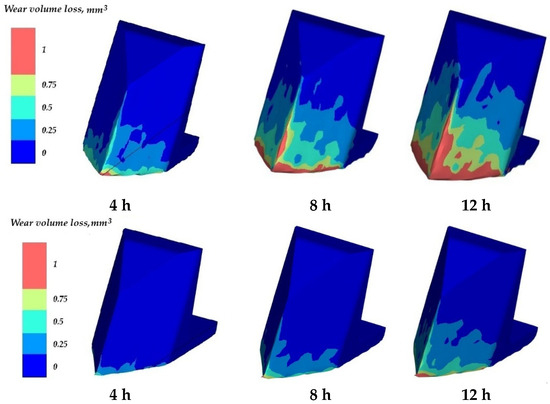
Figure 6.
Results of wear on the working surface at different time intervals.
As shown in the figure, in both cases, anchor wear begins at the nose, forming a chamfer, and progresses along the front and bottom edges on both sides. The amount of wear increases with longer operating time.
The basic anchor sample has greater abrasive wear than the hardened version. Wear covers the entire working surface on both sides. A large chamfer with a wear value of 0.75–1 mm3 has formed at the front. There is similar wear on both the lower edge and the front edge. Wear of 0.25 mm3 starts at the bottom of the working surface and increases to 0.75 mm3 at the top. In some places, there are areas of wear up to 1 mm3.
The hardened anchor sample has insignificant wear of up to 1 mm3 in the nose section. On the lower side edge on both sides, the wear is only 0.25–0.5 mm3. Wear of up to 0.25 mm3 begins at the bottom of the working surface and reaches only the middle.
Based on the results of the working surface wear, the dependence graphs of the wear volume on time were constructed, and are shown in Figure 7. Detailed wear values are presented in Table 5.
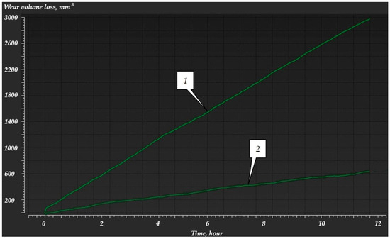
Figure 7.
Graphs showing the dependence of wear volume on time: (1) base, (2) hardened.
Table 5.
Results of computer modeling using the Rocky Dem software package.
Figure 8 shows the abrasion intensity of the anchor’s working surface. This value characterizes the degree of material deformation due to particle friction, or, in other words, shear work, and is used to visualize areas where large tangential deformations, ruptures, and destruction occur, i.e., high friction. In this case, what is happening shows how much the working surface of the anchor is “cut,” “ground down,” or “deformed” in each section of the flow over time.
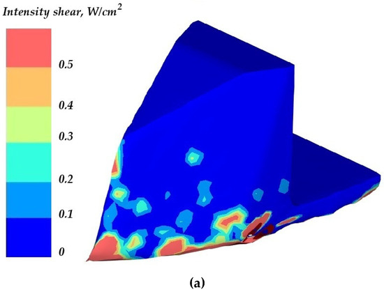
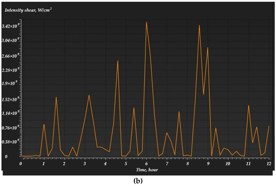
Figure 8.
Intensity shear at different time intervals: (a) on the anchor sample, (b) on the graph.
As shown in the figures, wear on the working surface is uneven, as soil particles affect some areas more than others. For example, the anchor nose is the first to encounter resistance from hard soil and, therefore, wears out more quickly. The rest of the working surface is worn down by loose soil.
Field tests of coulter anchor samples were conducted to verify the reliability of the results of theoretical studies and computer modeling.
Field tests were conducted on the territory of the North Kazakhstan Agricultural Experimental Station (AES) LLP [39,40] as part of a grant project 217 “Development of Science,” project: AP08856407 “Development of a wide-swath seeder for sowing seeds and differentiated application of mineral fertilizers at different specified depths” for the period 2020–2022 [41].
When conducting research to determine soil hardness during testing of agricultural machinery, GOST 20915-2011 “Testing of agricultural machinery. Methods for determining test conditions” [42] was used when conducting research to determine soil hardness when testing agricultural machinery. This standard establishes methods for determining the soil type, moisture content, and hardness necessary to assess the machinery’s performance quality using a hardness tester.
For a general analysis of soil properties, methods were used in accordance with GOST 5180-2015 (laboratory methods) [43] and GOST 30672-2019 (field tests) [44].
Soil hardness and moisture content were measured on the testing day at five locations diagonally across the site, at depths of 0–5 cm, 5–10 cm, and 10–15 cm. A Wile Soil device was used to determine hardness, and an Aquaterr T-350 soil moisture meter (Aquaterr Instruments & Automation, LLC, Costa Mesa, CA, USA) was used to measure moisture content.
Sixty hectares of sowing area were allocated for the experiments, where seeds and fertilizers were sown at different specified depths in two 6 h shifts. Seeds and fertilizers were sown at a working speed of 8 km/h.
The obtained results of field tests of the KATU-6 seeding complex aggregated with a John Deere 9430 tractor (Deere & Company (John Deere), Waterloo, IA, USA), where coulters with the tested anchors are installed on the seeding complex, are presented in summary Table 6.
Table 6.
Test conditions for laboratory–field, operational–technological tests of the PK-6.2 seeding complex.
The results and analysis of the studies are shown in Figure 9, which shows the condition (appearance) of the anchor samples after field tests.
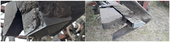
Figure 9.
Anchor samples after field testing.
Upon completion of field testing, anchor samples were removed from the coulter. They were then cleaned and visually inspected. The visual inspection revealed signs of abrasive wear and the data were recorded in Figure 10.
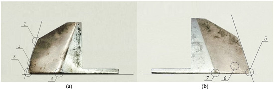
Figure 10.
Abrasively worn anchor samples: (a) base, (b) hardened.
The following types of wear are observed in the base sample of the coulter anchor:
- The front edge is uneven, the straightness of the edge is lost, position 1;
- The working surface has notches, grooves, abrasions from large soil particles, and grooves from small soil particles on both sides, position 2;
- A large chamfer has formed in the nose section, position 3;
- A rounded chamfer has formed along the lower side edge on both sides, there are notches, position 4.
The hardened coulter anchor sample was less susceptible to wear:
- A small chamfer has formed in the nose section, position 5;
- The working surface has abrasions from soil particles on both sides, position 6;
- A slight chamfer has formed along the lower side edge on both sides, position 7.
Next, after visual inspection, the samples were weighed, and the wear mass was calculated. The data obtained are shown in Table 7.
Table 7.
Results of field tests.
Field tests showed that the weight of the anchor samples decreased. Samples No. 6–10 showed less wear and, accordingly, greater weight compared to samples No. 1–5, as they were coated with a T-620 electrode. As a result, the surfacing strengthened the working surface by forming a new structure that differed from the base metal’s structure and exhibited increased hardness and wear resistance. The mass difference ranged from 10.28 to 17.17 g, which significantly affects the durability of the working body.
For each test condition, wear measurements were obtained from multiple specimens, and the results are presented as mean values with associated variability. The standard error of the mean was calculated according to standard statistical procedures and was found to be relatively small compared to the mean wear values, indicating good repeatability of the experiments.
Based on the calculated standard errors, 95% confidence intervals were determined for the mean wear values. The confidence intervals of the hardened and non-hardened samples show limited overlap, supporting the robustness of the observed differences.
Statistical differences between the hardened and non-hardened samples were evaluated using a two-sample Student’s t-test at a significance level of p = 0.05. The analysis confirmed that the differences in wear between the groups are statistically significant (p < 0.05).
The applied statistical tests demonstrate that the observed reduction in wear due to surface hardening is not random, but reflects a systematic effect of the applied treatment.
3. Results and Discussion
As can be seen from the research results (Table 3 and Table 5, and Table 7), the lowest wear and, accordingly, the highest wear resistance are observed in the computer simulation results: for the base variant—21.91 g—and for the reinforced variant—8.93 g. The results of the field tests exceed the values of the computer modeling: for the base variant—by 2.54 g—and for the reinforced variant—by 1.69 g. The greatest wear was determined by theoretical calculations: for the basic version—27.47 g—and for the reinforced version—11.91 g.
Based on the theoretical studies, computer modeling, and field tests, graphs were constructed showing the dependence of the wear mass of the base and hardened anchors on their hardness (Figure 11 and Figure 12).
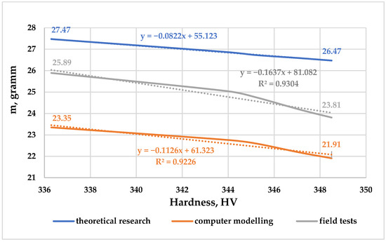
Figure 11.
Dependence of the wear mass of the base anchor on its hardness.
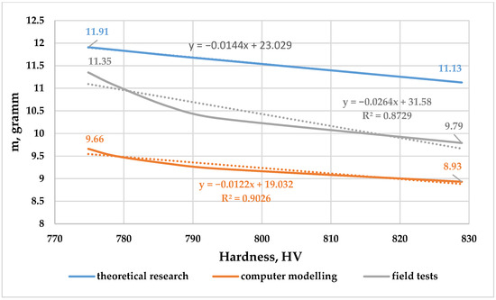
Figure 12.
Dependence of the wear mass of the hardened anchor on its hardness.
Conclusions based on the graphs obtained:
- The theoretical dependence of the wear mass on its hardness is described by a linear function as, according to the results of the computer modeling and field tests, hyperbolic;
- According to the results of the theoretical calculations, the hardening of the anchor sample with a welded layer of a T-620 electrode improved the material’s resistance to abrasive wear and showed a 2.31-fold reduction compared to the base analogue; the wear according to the results of the computer modeling showed 2.41 and the field tests showed 2.36;
- The mass of the base anchor sample after field testing was 90.2%, i.e., the wear was 9.8%, and the mass of the hardened sample was 96%, i.e., the wear of the hardened sample was only 4%.
The analysis of the load-bearing capacity and deformations of the anchor after loading showed that the 2.45-fold reduction in the wear of the hardened sample indicates a similar increase in its wear resistance.
The theoretical assessment of the wear is based on idealized assumptions, in particular:
- A constant contact pressure and sliding speed;
- The uniformity of the abrasive environment;
- The constancy of the mechanical properties of the material during wear.
Under real operating conditions, these assumptions are not met, which leads to an overestimation of the calculated wear values (26–27 g and 11–12 g, respectively).
The DEM model takes into account the discrete nature of the soil environment, but has a number of limitations:
- A simplified particle shape is used (spherical or quasi-spherical);
- Micro-destruction, oxidation, and soil adhesion processes are not taken into account;
- The contact parameters (coefficients of friction, recovery, and adhesion) are assumed to be constant.
As a result, DEM modeling tends to underestimate the actual wear, which is reflected in the values obtained (~22 g and ~9 g).
Field tests were conducted under the following conditions:
- Variable soil moisture and particle size distribution;
- An unsteady load on the working body;
- The partial self-hardening of the surface due to plastic deformation and work hardening.
These factors lead to the experimental wear values (24–25 g and 10–11 g) occupying an intermediate position between the theoretical and modeled data.
For hardened samples, the discrepancy is less pronounced, which can be explained by:
- The more stable mechanical properties of the hardened layer;
- The lower sensitivity of the wear to local changes in the contact conditions;
- The reduced role of plastic deformation in the overall wear mechanism.
Thus:
- The theoretical model sets the upper estimate of wear;
- DEM modeling gives the lower limit;
- Field tests confirm the adequacy of both approaches, falling within ±20–30% of the calculated values.
This discrepancy is typical for tasks involving the abrasive wear of soil-working implements and does not contradict existing experimental data, which confirm the correctness of the chosen research methodology.
The observed differences between the theoretical calculations, DEM modeling results, and field experimental data are systematic in nature and are due to the varying degrees to which physical wear processes are considered in each approach. The theoretical model assumes the stationary contact conditions with constant values of a normal pressure and sliding velocity, resulting in a linear accumulation of wear over time. In field conditions of the interaction between the working body and the soil, these parameters are non-stationary, which is accompanied by a redistribution of contact stresses and the partial relaxation of loads, as a result of which the actual wear is lower than the theoretically calculated limit values.
For hardened samples, the discrepancy between the theoretical, numerical, and experimental results is less pronounced. This is due to the more stable mechanical properties of the hardened layer and the reduction in the role of plastic deformation in the overall wear mechanism. As a result, the wear of such samples is less dependent on local fluctuations in the contact conditions, which ensures a higher convergence of the results obtained by different methods.
Thus, the theoretical model determines the upper limit of possible wear, DEM modeling sets the lower estimate, and the results of the field tests confirm the adequacy of both approaches, falling within the expected range between them. The discrepancies obtained do not indicate the incorrectness of the methods used, but reflect their physical and methodological limitations, characteristic of the abrasive wear tasks of the soil cultivation working body.
The following tasks were carried out as part of the research to achieve the set goal.
First, a coulter anchor for a variable-depth seed and fertilizer application was selected as the study object. Since the anchor is a new structural element of the coulter, it was necessary to select a strengthening technology and justify it based on an analysis of the current research presented in the introduction.
Second, theoretical studies and calculations were conducted to determine the anchor’s wear mass. A final formula was derived, a mathematical model showing the relationship between the anchor’s wear mass and its hardness.
Next, computer modeling capabilities were applied; in particular, the Rocky DEM program, which was used to obtain data on the volume of wear on the working surface at different time intervals. The volume of wear was converted into the mass of the anchor wear, taking into account the density of the material.
Field tests were conducted to verify the reliability of the results of the theoretical studies and computer modeling, which showed an average value between the data from the two.
4. Conclusions
During the research, the change pattern in the wear mass of the working surface of the coulter anchor depending on its hardness was studied. It was based on the study of the soil particles’ interaction with each other using the Hertz–Minlin model and the working surface with soil particles using Archard’s law. It was determined that an increase in hardness leads to a proportional decrease in wear, so that when hardness increases several times, the wear mass decreases by approximately the same amount.
The experimental results confirm the basic assumption of Archard’s law: an increase in hardness is practically proportional to an increase in the wear resistance. Although the coefficients 2.36–2.45 do not coincide exactly, a discrepancy of less than 5% can be considered an experimental error caused by variations in the soil environment and surface roughness.
Thus, the relationship is inversely proportional and is described by a hyperbolic function of the form m ∼ 1/H.
The use of the T-620/E10-UM60-GP surfacing electrode as a strengthening layer made it possible to increase the hardness of the base anchor sample to an average of 792.51 HV, which corresponds to an increase in the hardness of approximately 2.45 times compared to the initial state. This increase in hardness indicates the formation of a highly wear-resistant surfaced structure capable of effectively resisting the abrasive and abrasive-impact wear characteristic of the operating conditions of coulter anchors in soil environments.
From an engineering point of view, the results obtained allow us to recommend the use of T-620/E10-UM60-GP electrode surfacing to strengthen the most loaded and intensively worn areas of the anchor, primarily the nose and cutting edge. The use of this hardening method helps to increase the service life of the part, reduce the frequency of its replacement, and, as a result, reduce the operating costs of agricultural machinery maintenance. In addition, repair surfacing can be considered as an alternative to complete the replacement of the anchor, which is especially relevant in the serial operation of the equipment.
From an economic point of view, the use of the T-620/E10-UM60-GP electrode is justified in conditions of intensive abrasive wear, where the increase in the service life of the part outweighs the costs of the surfacing materials and technological operations. However, at low-wear levels or during short-term operation, it may be more expedient to use less expensive hardening electrodes or surface-hardening methods. Thus, the choice of surfacing technology should be made taking into account the operating conditions, the required service life of the part, and the economic efficiency.
This work is also being continued in research within the framework of grant project 217 “Development of Science,” project: IRN AP22783508 “Development of a central pneumatic sowing system with an automatic control unit for wide-swath sowing complexes for grain crops” for the period 2024–2026.
Author Contributions
Conceptualization, M.A. and K.U.; methodology, M.A. and K.U.; software, T.T.; formal analysis S.N.; investigation, M.A. and K.U.; data curation, T.T., K.I. and K.V.; writing—original draft preparation, M.A. and K.U.; writing—review and editing, M.A., K.U. and S.N.; visualization, K.I. and K.V.; supervision, M.A., K.U. and S.N.; project administration, M.A. All authors have read and agreed to the published version of the manuscript.
Funding
This research was funded by the Ministry of Science and Higher Education of the Republic of Kazakhstan, grant numbers AP08856407 and AP22783508.
Institutional Review Board Statement
Not applicable.
Informed Consent Statement
Not applicable.
Data Availability Statement
The original contributions presented in this study are included in the article. Further inquiries can be directed to the corresponding author.
Conflicts of Interest
The authors declare no conflicts of interest.
Abbreviations
The following abbreviations are used in this manuscript:
| NCJSC | Non-commercial Joint Stock Company |
| DEM | Discrete Element Method |
| CVA | Carbide vibro-arc |
| HVOF | High-velocity oxygen fuel |
| PEMP | Point electromechanical processing |
| AES | Agricultural Experimental Station |
| AZH | Arc spot hardening |
| UCI | Ultrasonic Contact Impedance |
| LLP | Limited Liability Partnership |
References
- Denisenko, M.I. Regarding the Issue of Restoration and Strengthening of Details of the Working Bodies of Soil Machinery. Central Ukrainian Scientific Bulletin. Tech. Sci. 2023, 7, 86–99. [Google Scholar] [CrossRef]
- Malvajerdi, A.S. Wear and coating of tillage tools: A review. Heliyon 2023, 9, e16669. [Google Scholar] [CrossRef] [PubMed]
- Wang, Y.; Li, D.; Nie, C.; Gong, P.; Yang, J.; Hu, Z.; Li, B.; Ma, M. Research Progress on the Wear Resistance of Key Components in Agricultural Machinery. Materials 2023, 16, 7646. [Google Scholar] [CrossRef] [PubMed]
- Yaşar, S.S.; Bülent, Ç. Surface Coating Applications on Active Parts of Tillage Machines. Turk. J. Agric.—Food Sci. Technol. 2020, 8, 92–99. [Google Scholar] [CrossRef]
- Mikhalchenkov, A.M.; Feskov, S.A.; Kubyshkin, A.V. Theoretical study of the wearing process of the abrasive fraction of soil during its motion on the working surface of the components of soil tilling tools. Tract. Agric. Mach. 2024, 91, 199–205. [Google Scholar] [CrossRef]
- Joy, A.A.; Kehinde, D.F.; Ayobami, I.A.; Oluwatomiwa, K.P.; Ayodeji, M.A.; Jacob, K.A.; Mamello, P.S. The protective roles of citrus flavonoids, naringenin, and naringin on endothelial cell dysfunction in diseases. Heliyon 2023, 9, e17166. [Google Scholar] [CrossRef]
- Kostencki, P.; Stawicki, T.; Krolicka, A. Wear of the working parts of agricultural tools in the context of the mass of chemical elements introduced into soil during its cultivation. Int. Soil Water Conserv. Res. 2021, 9, 229–240. [Google Scholar] [CrossRef]
- Yazıcı, A. Wear on steel tillage tools: A review of material, soil and dynamic conditions. Soil Tillage Res. 2024, 242, 106161. [Google Scholar] [CrossRef]
- Golubev, I.G. Analysis of reconditioning and hardening methods applied for the working tools of tillage machines. BIO Web Conf. 2021, 37, 00001. [Google Scholar] [CrossRef]
- Antonov, A.A.; Golubev, I.G. Materials of the International Scientific and Practical Conference Dedicated to the 20th Anniversary of the Department of Technical Operation of Transport. pp. 166–169. Available online: http://rgatu.ru/archive/sborniki_konf/12_10_20/sbor_1.pdf (accessed on 12 October 2020).
- Dudnikov, A.A.; Belovod, A.I.; Pasyuta, A.G.; Kelemesh, A.A.; Gorbenko, A.V. Technological methods of increasing the durability and resource of working parts of tillage machines. Technol. Audit. Prod. Reserves 2015, 5, 4–7. [Google Scholar] [CrossRef]
- Aduov, M.A.; Nukusheva, S.A.; Kaspakov, E.Z.; Tulegenov, T.K.; Isenov, K.G.; Volodya, K.; Uteulov, K.T. Patent for Invention No:36760//Coulter for Applying Seeds and Fertilisers at Various Specified Depths. Available online: https://gosreestr.kazpatent.kz/Invention/Details?docNumber=372012 (accessed on 20 November 2024).
- Subbotin, S.I.; Fomin, S.D.; Gapich, D.S. Simulation of the process of interaction of soil particles with the surface of the working body strengthened with a longitudinal reinforcing roller. Proc. Low. Volga Agro-Univ. Comp. 2024, 4, 348–355. [Google Scholar]
- Senchishin, V.S.; Pulka Ch, V. Modern Methods of Surface Treatment of Working Parts of Soil Cultivation and Harvesting Agricultural Machinery (Overview). Autom. Weld. 2012, 9, 48–54. Available online: https://patonpublishinghouse.com/rus/journals/as/2012/09/07 (accessed on 10 July 2012).
- Arsenoaia, V.N.; Munteanu, C.; Lupu, F.C.; Istrate, B.; Benchea, M.; Melnic, I. Field Performance and Wear Behavior of Atmospheric Plasma Spraying (APS) Coated Discs Used in Agricultural Disc Harrows. Agriculture 2026, 16, 114. [Google Scholar] [CrossRef]
- Grebnev, Y.V.; Zharkova, V.F.; Grebnev, D.Y.; Antonov, N.O.; Tarabanovsky, A.Y. Development of highly efficient manufacturing technology for working bodies of tillage machines. Sci. Look Into Future 2020, 17, 16–19. [Google Scholar] [CrossRef]
- Mikhalchenkov, A.M.; Ulyanova, N.D.; Feskov, S.A.; Gutsan, A.A. Mechanical properties of heat-strengthened steel 65G surface-reinforced with hard-alloy surfacing. Agric. Eng. 2021, 3, 63–68. [Google Scholar] [CrossRef]
- Mikhalchenkov, A.; Filin, Y.; Petrakova, N. Substantiation of technologies for strengthening and restoring parts of the working bodies of the high-speed plow of the PSKu. Sci. Cent. Russ. 2023, 62, 46–53. [Google Scholar] [CrossRef]
- Drobota, A.; Balaeva, E.; Eliseeva, V. Technological aspects of increasing the wear resistance of the working surface of the dump with a modified surface. X International Scientific Siberian Transport Forum. Transp. Res. Procedia 2022, 63, 2921–2926. [Google Scholar] [CrossRef]
- Dudnikov, A.; Dudnik, V.; Gorbenko, O.; Kelemesh, A. Vibration technologies in the restoration of the working bodies of agricultural machines. Vib. Eng. Technol. 2021, 1, 100. [Google Scholar] [CrossRef]
- Sharifullin, S.N.; Adigamov, N.R.; Adigamov, N.N.; Solovev, R.Y.; Arakcheeva, K.S. Surface hardening of cutting elements agricultural machinery vibro arc plasma. J. Phys. Conf. Ser. 2016, 669, 012049. [Google Scholar] [CrossRef]
- Pryshlyak, V.M.; Yaropud, V.M.; Kulizhsky, V.M.; Ivashko, V.I. Strengthening of Low-Resource Parts of Working Bodies of Soil Cultivation Equipment. Collection of Scientific Works No. 3/2009. Available online: https://repository.vsau.org/getfile.php/2071.pdf (accessed on 19 March 2009).
- Adigamov, N.; Gimaltdinov, I.H.; Galiev, I.G.; Gricenko, A.V.; Kazakov, Y. Processing the results of experimental studies of the use of technologies of integrated microplasma hardening of working units and parts of agricultural machines. Vestn. Kazan State Agrar. Univ. 2023, 18, 68–75. [Google Scholar] [CrossRef]
- Yakovlev, S.; Kurdyumov, V.; Ayugin, N.; Mishanin, A. Results of metallographic observations of cultivator shares after spot electromechanical processing. IOP Conf. Ser. Earth Environ. Sci. 2022, 979, 012047. [Google Scholar] [CrossRef]
- Sagdoldina, Z.; Tyurin, Y.; Berdimuratov, N.; Stepanova, O.; Magazov, N.; Baizhan, D. Electrofrictional Hardening of the 40Kh and 65GSteels. Coatings 2023, 13, 1820. [Google Scholar] [CrossRef]
- Slinko, D.; Dorokhov, A.; Denisov, V.; Dobrin, D. Improvement of Technology of Strengthening of Working Bodies of Tillage Machines. Agric. Mach. Maint. Repair 2018, 8, 621.791. Available online: https://panor.ru/en/articles/sovershenstvovanie-tekhnologii-uprochneniya-rabochikh-organov-pochvoobrabatyvayushchikh-mashin/20009.html# (accessed on 19 August 2018).
- T-620 Electrodes [Text]. Available online: https://electrode.com.ua/ru/materiali_dlja_naplavki/elektrodi/t-620.html (accessed on 22 July 2017).
- Electrodes for Surfacing [Text]. Available online: https://ckmt.ru/artic/elektrody-dlya-naplavki.html (accessed on 16 April 2011).
- Rocky DEM (Discrete Element Method) Software Package. Available online: https://www.rocky-dem.ru/industries/heavy-equipment/ (accessed on 12 August 2021).
- Qiu, X.; Potapov, A.; Song, M.; Nordell, L. Prediction of Wear of Mill Lifters Using Discrete Element Method. In Proceedings of the SAG 2001 Conference, Vancouver, BC, Canada, 30 September–3 October 2001; Available online: https://www.researchgate.net/publication/286447937 (accessed on 10 December 2015).
- Steel 65G, General Information [Text]. Available online: https://1metal.com/infosteel-steel_65g.html (accessed on 26 January 2015).
- MET-U1A—Portable Ultrasonic Hardness Tester [Text]. Available online: https://olmatek.kz/catalog/nerazrush_control/tverdomery-portativnye/met-u1a/ (accessed on 20 December 2025).
- CAS MW-II Micro Weighing Scale (Discontinued) [Text]. Available online: https://expresservice.com.ua/catalog/laboratornie-vesy/laboratornie-vesi-cas-mw-ii-300gr (accessed on 24 May 2015).
- Delaney, B.; Wang, Q.J. Archard’s Law: Foundations, Extensions, and Critiques. Encyclopedia 2025, 5, 124. [Google Scholar] [CrossRef]
- Kapustin, A.N. Basics of the Theory and Design of Machines for Basic and Surface Soil Cultivation, Seeding Machines and Fertiliser Spreaders; Tomsk Polytechnical University Publishing House: Tomsk, Russia, 2013; p. 134. Available online: https://portal.tpu.ru/SHARED/l/LEXCOL/educationalwork/Tab1/posobie_raschet.pdf (accessed on 16 September 2009).
- Alpas, A.T.; Bhattacharya, S.; Hutchings, I.M. 4.5 Wear of Particulate Metal Matrix Composites. Compr. Compos. Mater. II 2018, 4, 137–172. [Google Scholar] [CrossRef]
- Liu, T.; Yu, J.; Wang, H.; Yu, Y.; Li, H.; Zhou, B. Modified Method for Determination of Wear Coefficient of Reciprocating Sliding Wear and Experimental Comparative Study. J. Mar. Sci. Eng. 2022, 10, 1014. [Google Scholar] [CrossRef]
- Mudarisov, S.; Gabitov, I.; Lobachevsky, Y.; Farkhutdinov, I.; Kravchenko, L. Systematic Evaluation and Experimental Validation of Discrete Element Method Contact Models for Soil Tillage Simulation. AgriEngineering 2025, 7, 256. [Google Scholar] [CrossRef]
- North Kazakhstan Agricultural Experimental Station [Text]. Available online: https://sk-shos.kz/ (accessed on 24 December 2021).
- New Seed Drill Presented by KATU Scientists [Text]. Available online: https://kazatu.edu.kz/ru/news/novuu-sealku-prezentovali-ucenye-katu (accessed on 24 November 2025).
- Scientific Research (Applied, No. 178) Completed in 2022. No. AR08856407 ‘Development of a Wide-Chamber Seeder for Sowing Seeds and the Differential Application of Mineral Fertilisers at Various Specified Depths’ [Text]. Available online: https://www.ncste.kz/en/informacziya-po-zavershennyim-nauchnyim-issledovaniyam-2022-g (accessed on 10 January 2023).
- GOST 20915-2011; Testing of Agricultural Machinery. Methods for Determining Test Conditions. Standardinform: Moscow, Russia, 2013.
- GOST 5180-2015; Soils. Methods for Laboratory Determination of Physical Characteristics. Standardinform: Moscow, Russia, 2016.
- GOST 30672-2019; Soils. Field Tests. General Provisions. Standardinform: Moscow, Russia, 2019.


Disclaimer/Publisher’s Note: The statements, opinions and data contained in all publications are solely those of the individual author(s) and contributor(s) and not of MDPI and/or the editor(s). MDPI and/or the editor(s) disclaim responsibility for any injury to people or property resulting from any ideas, methods, instructions or products referred to in the content. |
© 2026 by the authors. Licensee MDPI, Basel, Switzerland. This article is an open access article distributed under the terms and conditions of the Creative Commons Attribution (CC BY) license.