Abstract
This article presents the results of a preliminary archaeological operation carried out in 2021 on the Mortella II wreck. It was designed as a continuation and complement to the excavation of the Mortella III wreck that was performed between 2010 and 2019 and to which it is historically linked: both ships were Genoese merchantmen sailing together, which sank in 1527 in the context of the 7th Italian War between France and Spain. The paper takes up the main outcomes of the lines of research on shipbuilding and artefacts (anchors and artillery). It discusses their characteristics, comparing them to other wrecks of similar Mediterranean origin. In this way, this work seeks to contribute to the knowledge of Mediterranean shipbuilding and the material culture of the Renaissance, which is currently little known.
1. Introduction
The Mortella II and III wrecks were discovered during a geophysical survey program led by the Centre d’Etudes en Archéologie Nautique—CEAN—(Center for Nautical Archaeology Studies) between 2005 and 2009 in the Gulf of Saint-Florent (Corsica, France). This survey, which combined acoustic and magnetometric detection techniques, led to the discovery of the two shipwrecks dating from the 16th century. The first, named Mortella II, was located in October 2005 at a depth of 47 m at the exit of the bay. The second, named Mortella III, was discovered in November 2006 at a depth of 38 m, 650 m south-east of the first [1] (Figure 1).
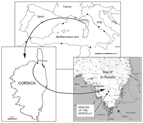
Figure 1.
Location of the Mortella II and III wrecks. The sites are named after the Genoese tower located at the western end of the bay of Saint-Florent, which is the nearest land reference point. Mortella I is an anchorage site located at the foot of the tower, where shards of ceramics attest to its activity over the past centuries.
Literature research led to the identification of the ships, two Genoese trading vessels, the Ferrara and the Boscaina, sunk in August 1527 during an episode of the seventh Italian war opposing France to the Republic of Genoa controlled by Spain [2] (pp. 148–150).
The first observations made at these sites at the time of their discovery, in particular with the completion of a survey by the DRASSM (French National Department for Underwater Archaeology) in 2007, initially demonstrated their high scientific interest. The prospect that they offered in shedding light on the Mediterranean shipbuilding of the Renaissance—which remains poorly known—led to the implementation of a study project. It was developed within the framework of a European research program (ModernShip project, ‘The structures of the Early Modern Mediterranean shipbuilding’, MSCA, Horizon 2020, GA 843337). The archaeological work initially focused on the Mortella III wreck, which is more accessible than the Mortella II, and six excavations were organized between 2010 and 2019. The recent finalization of this program has resulted in the publication of a monograph in English and French [2,3], as well as a recently published final review [4]. Then, a survey of the second wreck, Mortella II, the object of this article, was carried out in 2021.
1.1. Objectives and Stakes of the Archaeological Survey on the Mortella II Site
First, it was sought to undertake a general observation of the site, to carry out its complete mapping, and to position the visible archaeological remains precisely by means of a topographical survey. The goal of this work was to contribute to understanding the arrangement and dynamics of the site, to measure its archaeological potential, to help in the implementation of its monitoring, and to ensure its protection.
Another aim was to also undertake an observation of the hull remains, to characterize the type of construction. For this purpose, a trench was opened, in order to uncover a small portion of the hull. This was all the more necessary as the name of one of the ships, the Boscaina, appeared to have a potential eponym of Basque origin [3] (p. 207–208). It was therefore important to specify whether the shipbuilding tradition was of Mediterranean or Atlantic origin. This excavation also offered an opportunity to take wood samples for dendrochronology (see part 6).
Finally, the operation included a preliminary study of the artefacts visible on site: Documentation of the artillery, represented by port-pieces composed of wrought iron tubes and breeches accompanied by stone shot, was undertaken. The two anchors observed on the site were also documented and analysed. Lastly, the survey resulted in the collection and study of ceramics. It should be added that all these preliminary studies were undertaken from a comparative perspective with those carried out at the Mortella III site.
1.2. The Research Organisation and Team
The archaeological and historical interest of this operation led to the collaboration of several European institutions and research organizations—about fifteen in all—and researchers from various disciplines. It benefited from the scientific collaboration of the Spanish National Research Council (CSIC); the ForSEAdiscovery Consortium [5,6]; the Projet Commun de Recherche (PCR. i.e., Joint Research Project) ‘16th Century Ship’, which brings together, among others, the Groupe de Recherche en Archéologie Navale (GRAN), France; Centre d’Études en Archéologie Nautique (CEAN), France; Spanish National Research Council (CSIC), Spain; Sorbonne University, France, Università di Sassari, Italy; and Università di Genova, Italy. The project was carried out with the financial support of the French Ministry of Culture (DRASSM), the Collectivité de Corse (CdC), the European Union (Marie Sklodowska Curie Actions, Horizon 2020), and the Spanish National Research Council (CSIC) through its PIAR fund (Proyectos Intramurales para Arqueología en el exterior).
1.3. Operational Constraints
The study of the site came up against a major obstacle, which is the depth at which the wreck lies, and the operational difficulties that archaeological work at a depth of 47 m involves. It was nevertheless true that its historical link with the Mortella III wreck and the high archaeological value it represented made it difficult to conceive of completing the ‘Mortella project’ without carrying out a thorough incursion into this site. For this reason, an operation was organized, but it certainly represented both a technical and logistical challenge. Despite the operational constraints, and particularly the very short working time allowed at the sea bottom, the Mortella II wreck proved to be very rich, both in terms of the information gathered on the hull remains and the contribution of its artefacts to our knowledge of the material culture of the period.
The current article aims to present the preliminary results of this first intervention at the Mortella II site. It is divided into six themes: (1) Presentation of the historical and architectural profiles of the Mortella wrecks, (2) Excavation methodology, (3) General characteristics of the site and its arrangement, (4) Hull remains, (5) Wood study (these five parts are by Arnaud Cazenave de la Roche), (6) Anchors, (7) Ship tonnage and dimensions, and 8) Ordnance (these three parts are by Fabrizio Ciacchella). It should be added that the ceramics recovered during this operation, which are of exceptional scientific and heritage value, are presented as a separate article by Marco Milanese in this issue of Heritage.
2. A Short Historical and Typological Presentation of the Mortella Wrecks
2.1. Historical Context and Narrative of the Shipwrecks
Literature research carried out in parallel with the excavations in Italian, French, and Spanish archives and libraries has enabled us to draw up a historical portrait of these Genoese ships. We now know that they are the remains of the Boscaina and Ferrara, two trading ships attached to the port of Rapallo, located 25 km East of Genoa and allied to it. The discovery of two primary sources revealed their history. They were written by Agostino Giustiniani, bishop of Saint-Florent (Corsica, France) between 1514 and 1536, and Paolo Giovio (1483–1552), two authors who were contemporaries of the events [7,8]. They provide a double level of information:
1—First, regarding the general political context that led to the shipwrecks, in this case, that was the seventh Italian war (1526–1530). In 1527, the city of Genoa was besieged by a group of allied fleets known as the ‘League of Cognac’. This included the French fleet and those of Pope Clement VII, Venice, Florence, and the personal fleet of Andrea Doria, who was then the armed wing of the French King Francis I in the Mediterranean. Doria struck at Genoa, his own home town, then occupied by Charles V’s Spain. It is, therefore, to this tumultuous historical context that the Mortella wrecks refer. Indeed, we now know that the two Genoese ships, the Boscaina and the Ferrara, were returning from Sicily with a cargo of grain, and that their mission was to try to supply the city of Genoa, which was starving because of the blockade by the League of Cognac.
2—The second level of information concerns the shipwrecks themselves. The two Genoese authors tell us how the two ships were trapped in the gulf of Saint-Florent in the middle of August 1527. They had entered the port to make a stopover but were seen by a French war fleet. With no wind, they could no longer sail and were doomed to be overtaken by the French galleys, which approached the bay under full oars. With no means of escape, and little time before the French would join them, the crews hurried ashore after setting fire to their ships, to prevent them from falling into enemy hands.
2.2. The Typological Profiles of the Ships
A type of ship among the most important Mediterranean merchantmen of the Renaissance, they belong to a typology called nave in Italian. (plur. navi). They were particularly used by the Genoese as the main means of transport for trade and were built in private shipyards [9] (p. 46). Lacking Genoese sources, the main textual information on the constructive characteristics of navi is provided by Venetian authors such as Michele da Rodi [10] and Zorzi Trombetta da Modon [11] for the 15th century, or Teodoro de Nicolò [12] and the Ragusan Nicolò Sagri [13,14] for the 16th century.
In those centuries, the characteristics of the navi can be summarized as follows:
- -
- They were carvel built and fitted with two or usually three masts, although very rarely they could have four [15] (p. 230). The foremast and mainmast were equipped with square sails, while the mizzen mast (and the bonaventure, when present) had a lateen sail. They usually had two or three decks (coperte), including the upper deck (tolda). They were generally armed with several pieces of artillery for their defense.
- -
- The navi were the largest merchant ships in the Mediterranean [16] (p. 145). Manlio Calegari calculated that, in 1509, the average tonnage of a Genoese navi was 14,000 cantari 1, i.e., just under 670 metric tons net deadweight, corresponding to 930 m3 net tonnage. The smallest units were over 8000 cantari, or 380 metric tons net deadweight and 530 m3 net tonnage [17] (pp. 15–16).
- -
- Between 3000 and 8000 cantari (140–380 t) Genoese ships were classified as barche (sing. barca) [18] (pp. 15–16). This term can be quite confusing, as it can also refer to smaller boats [19] (p. 176). The largest barche had constructive characteristics similar to the navi, but were fitted with two or three masts and provided with two decks [16] (pp. 189–194).
The Mortella III ship (37 m long, 10.5 m at maximum breadth) with a tonnage estimated at 11,000 cantari, can thus be defined as a nave. On the other hand, as we will see in this article, it is estimated that the Mortella II ship was of smaller tonnage and probably met the definition of barca. The Mortella wrecks, together with the Lomellina wreck (1516, Villefranche-sur-Mer) [20], are exceptional testimonies of Genoese and, more broadly, Mediterranean shipbuilding during the Renaissance.
3. Excavation Methodology
3.1. Topographical Survey
A first-order geodetic network was set up with the materialization of six georeferenced points (PR). A reference point 0 was defined (PR1) and the Cartesian coordinates of each of these PRs were recorded. They were arranged in such a way as to define three 30 m lines oriented on a 260–80° axis, so as to come as close as possible to what appeared to be the probable axis of the wreck, represented by the axis of the shank of the large anchor (Figure 2). A secondary geodetic network was created, setting up points used to position the artefacts by trilateration or right-angle measurements (offset).
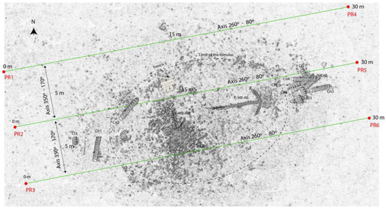
Figure 2.
Planimetry of the Mortella II site—Diagram of a geodetic network of six georeferenced points. Sketch: A. Cazenave de la Roche.
3.2. Orthophotography and Photogrammetry
The orthophoto/photogrammetry survey was implemented with a triple objective:
- -
- To obtain an orthography of the site, in interaction with the topographic survey,
- -
- To enable a precise positioning of the artefacts and generate a 3D image of the site,
- -
- To obtain a calibrated image of the site, allowing measurements to be taken, observations to be made, and, in the end, helping to understand the arrangement of the site.
3.3. Diving/Excavating Methods
To ensure optimum safety of the operation, and taking into account the nitrogen accumulation in human tissues, it was decided to limit the procedures to one 25′ dive per day with oxygen decompression (Figure 3b). The dredge was supplied by a high-pressure water pump (5 bars—60 m3/h) located on the U Saleccia, our base operation boat (Figure 3a).
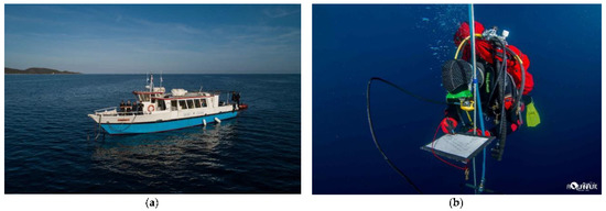
Figure 3.
(a): The U Saleccia, boat of the Center for Nautical Archaeology (CEAN). (b): Oxygen decompression stop. Photos: S. Jamme.
3.4. Preventive Conservation of the Artefacts and Site Conservation
A laboratory for the preventive conservation of artefacts was set up for this operation. The protocol for recovery of the artefacts from the site, recording them, packing them on board, transporting them to the laboratory, and taking care of them adopted the criteria inspired by the DRASSM ‘Guide de Conservation’ [21].
At the end of the operation, complete covering of the survey area was carried out: a sheet of geotextile was first laid over the remains. Then, the dredge was reversed so as to return the sediment and ballast gravels that had initially been extracted from the excavation area (Figure 4).
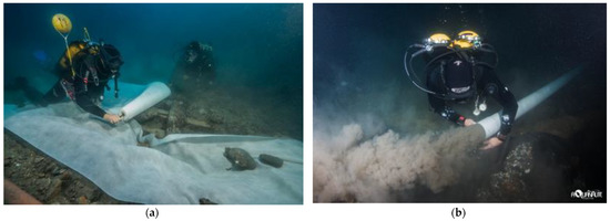
Figure 4.
Covering the trench area with geotextile (a) and re-siltation (b). Photos S. Jamme.
4. General Arrangement of the Site
An initial evaluation to the arrangement of the site was made at the time of its discovery in 2005, thanks to analysis of its SONAR image. This revealed an archaeological complex with a central tumulus made up of gravel and ballast stones extending over 28 × 15 m, i.e., slightly more than 400 m2 (Figure 5). The frequency of the acoustic waves (800 kHz) enabled sufficient penetration of the sediment to distinguish a regular and curved line of concretions on its northern slope, which seemed to mark the limits of the surviving hull (red line in Figure 5). Its measurements are 25 × 7 m, with a longitudinal axis oriented 260–80°.
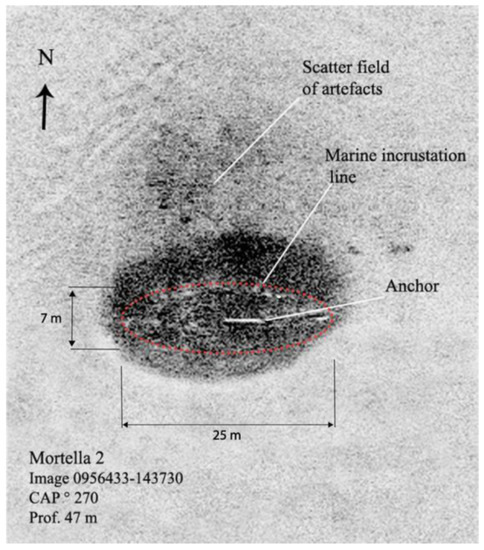
Figure 5.
SONAR image of the Mortella II site. Negative view with delimitation of a layer of concretions (in red). Image: CEAN.
The observations made during the 2021 survey fully confirmed this arrangement, which can be described as follows:
- -
- The site is located on a deep and dense muddy bottom typical of the Bay of Saint-Florent, whose anaerobic character is favorable to the preservation of organic artefacts. The depth is 46 m in the western part of the site with a 4% slope eastward, where the depth reaches 47 m.
- -
- The site is in the shape of an oval tumulus, whose bathymetric survey (DEM) coincided well with the SONAR image. The wreck is located under this tumulus composed of ballast gravel and stones. The gravel covers the whole site, while the stones, whose size varies between 10 and 30 cm in diameter, form a cluster of about 4 × 5 m globally situated in the center of the tumulus, although slightly offset westwards. Bathymetric survey examination allowed us to refine the wreck orientation estimate to an axis of 255–75° (Figure 6).
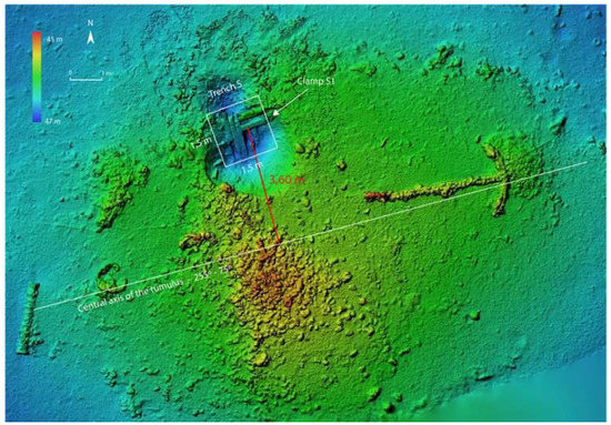 Figure 6. Mortella II: Estimated central axis of the site and distance between the S1 clamp.
- -
- The highest point of the tumulus is located at the top of the ballast stone pile, at 44.80 m. Its maximum thickness, in relation to the depth of the seabed, can be estimated at 1.70 m at its peak, with its lowest value at 1.00 m at the periphery (Figure 7).
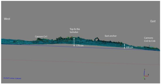 Figure 7. Photogrammetric profile of the Mortella II site.
- -
- The petrographic nature of the minerals that make up the gravel and ballast pebbles of the tumulus is similar to that observed at the Mortella III site. The pebbles are essentially sandstone with calcite veins and probably come from the rivers of the Genoa region, where they are typical.
As at the Mortella III site, the artefacts visible at the Mortella II site are mainly represented by wrought iron artillery pieces with hoops: six tubes and five breeches; one large anchor of 3.95 m and a small incomplete one with an estimated initial length of 2.55 m (±65 cm); ceramic shards: mainly earthenware, organic artefacts represented by ropes, most of them burnt, a little cask, and a bovine bone found in the upper part of the tumulus; various unidentified artefacts.
Finally, it should be noted that the arrangement of the Mortella II site, although smaller than Mortella III site, presents striking similarities with the latter:
- (a)
- The orientation of the two wrecks is similar, with a general east–west axis
- (b)
- The distribution of the artefacts is also similar:
Ceramics are essentially dispersed in the eastern part of both sites, which in the case of Mortella III corresponds to the stern area. This archaeological evidence is in fact logical, as the living and cooking areas were located at the stern of the ship.
In the Mortella III wreck, eight out of the ten artillery pieces are located in the stern area at the east end, and two in the bow area, at the west end. The Mortella II pattern is similar: four guns at the east end of the wreck, and two at the west end.
These factors suggest that the eastern part of the Mortella II wreck is the stern of the ship and the western end the bow.
5. Hull Remains
5.1. General Arrangement
The surveyed area revealed an architectural complex corresponding to a portion of the charred end of the ship’s frames. Nine oak timbers appeared in the trench named the S area, which was opened up in a square of 1.5 × 1.5 m, on the northern periphery of the site, an area which, considering the shape of the tumulus, should be situated around the level of the ship’s maximum breadth (Figure 8).
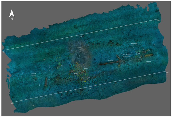
Figure 8.
Post-excavation ortho-photography of the Mortella II site II. Image Stéphane Jamme. Processing: Brandon Mason.
Seven timbers lay parallel to each other, placed in the transverse direction of the wreck with an overall north–south orientation. Interpreted as frames, they were named M0, M1A and M1B, M2, M3A and M3B, and M4 (Figure 9). Under them, the remains of the planking were observed. Finally, two timbers ran transversely over the frames. Interpreted as clamps, they were named S1 and S2, which would correspond to the fourth and fifth clamps (named starting from the bottom), reinforcing the assembly between the first and second futtocks. This assumption was supported by several factors.
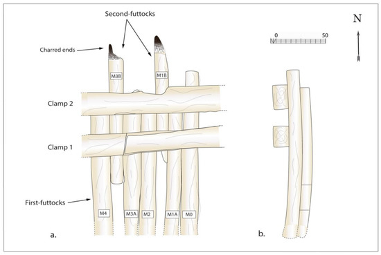
Figure 9.
Planimetry (a) and cross-section (b) of the architectural remains in the trench S. Drawing A. Cazenave de la Roche.
Indeed, it seems unlikely that clamp S1 and S2 could correspond to the foot-wale and the bilge-clamp, because it seems very improbable that the fire would have reached so low a level under the water-line. Moreover if we were dealing with these first clamps covering the assembly between the floors and first-futtocks, we surely would have found traces of sills, which was not the case. On the other hand, the type of scarf observed between the two frames was not the one usually found between the floor-timber and the first-futtock, which is generally provided with a mortise.
In view of the above, all the evidence suggests that—following the Mortella III layout—we were dealing with clamps n° 4 and 5 covering the first and second-futtocks, delimiting the end of the hull remains and the fire line.
Finally, the architectural complex presents an inclination of 28% northwards, i.e., 15° from the horizontal (Figure 10). This slope is clearly very low in relation to the height of the assembly between the first and second futtocks.
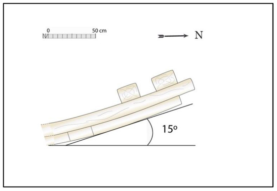
Figure 10.
Cross-section of architectural remains (Trench S).
Indeed, at the same level, the inclination of the hull of the 16th century Calvi I wreck (overall length 25 m, maximum beam 7.80 m) is about 50° from the horizontal [22] (p. 96). As the size of the ship increases, this inclination decreases sharply, but even for a larger ship such as the Mortella III (overall length 37 m, maximum breadth 10.50 to 11 m), the degree of inclination is still 37° (Figure 11).
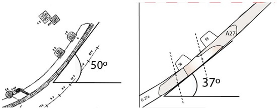
Figure 11.
Cross-section of the architectural remains at the same level as Figure 10 on Calvi I (left) and Mortella III wrecks.
The lower degree of the hull inclination of the Mortella II ship, as observed in the S trench, indicates a probable slant of the wreck on its northern side, to an extent that remains undetermined but certainly greater than 15°. This layout is consistent with the presence of a scattered artefacts field visible on the SONAR image on its northern slope (Figure 5).
Arrangement: A curious fact, which undoubtedly constitutes the peculiarity of this set, is the arrangement of the frames in pairs, i.e., their double arrangement. In other words, we are not dealing with a sequence of one room for one or two empty spaces, as in the other Renaissance wrecks known to us, but with two rooms for one space. Each of the pairs M0/M1, M2/M3, and M4/M5 forms a double frame separated from each other by an empty space with a scantling of 9 to 12 cm (Figure 8).
This arrangement results in strong hull sides. However, if we were to follow the logic of this arrangement, we would probably end up with a rather light hull bottom, and a sequence of floor-timbers alternating one room with one and a half to two spaces (Figure 12). Nevertheless, this conclusion would only be correct if the arrangement observed in the narrow window of the trench S was the same for the whole framing. In any case, only a complementary excavation of the hull towards the keel could provide confirmation of this layout.
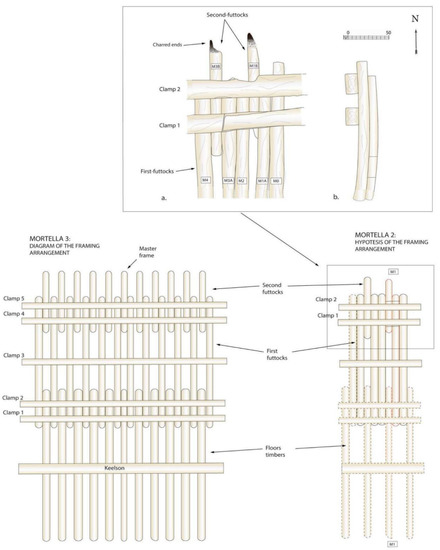
Figure 12.
Hypothesis of the arrangement of the hull structures of the Mortella II ship and comparison with that of the Mortella III. Drawing: Arnaud Cazenave de la Roche.
Apart from the fact that the generalization of this disposition needs to be confirmed by observation, the curious arrangement of the frames observed in the excavation trench raises an issue. It is the only one we know of in 16th century shipbuilding and cannot be compared with the double framing that appeared in the 18th century, which were very different in nature. Finally, it should be noted that this layout differs from that of the Mortella III or the Lomellina wrecks (Villefranche-sur-Mer, France, 1516) which are provided with single first-futtocks, resulting in a sequence of floor-timbers of approximately one room for one empty space (Figure 12).
5.2. The Frames
The remains of seven frames were found in the survey area (Figure 13).
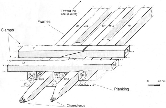
Figure 13.
Isometric sketch of the arrangement of the architectural remains (Trench S). Diagram: Arnaud Cazenave de la Roche.
Assemblies: Two of them are made up of two timbers joined laterally, named M1A/M1B and M3A/M3B. The former are the only ones whose assembly can be observed, fixed by two circular iron nails of 15 mm diameter overlapping under the clamps. The surfaces of the two pieces in contact are smooth and flat. The ends of the M1B and M3B frames, which form the outer limit of the assembly, are deeply charred.
Dimensions (Table 1). Molded: 13 to 19 cm (average 15.5 cm). Sided: 13.8 to 15.2 cm (average 14.8 cm).

Table 1.
Mortella II hull timbers.
5.3. The Clamps
The clamps are spaced 15 to 20 cm apart and cover the frames on which they are notched. As the frames are placed edge to edge under the clamps in a continuous manner, without any space left, the notches are morphologically adapted to the different frame heights (Figure 14).
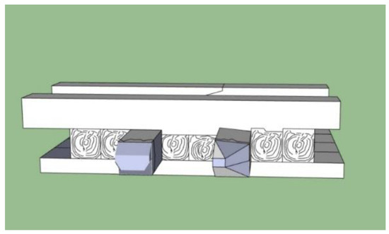
Figure 14.
Three-dimensional diagram of the hull profile in trench S. Sketch: Jesús Guevara.
The longitudinal section of the clamps allows us to see how their lower part was literally ‘sculpted’ to fit the irregular upper surface of the frames (Figure 15). Finally, it should be noted that the S1 clamp pieces are assembled with a flat horizontal scarf, similarly to those observed on the Mortella III wreck.
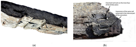
Figure 15.
(a) Lower face of the S2 clamp. Note the notches adapted to the morphology of the planking and the traces of iron nails. (b) Planking fastening system: nail tips are clenched over the inner face of the frame. The metal concretions stuck to the wood retain their print. Photo: Fabien Langenegger.
The clamps and frames are fastened with iron nails, most of which were circular in section, although traces of several square nails were also observed (Figure 15a,b). This fastening system is similar to that observed on the Mortella III wreck. No traces of tree-nail were found.
5.4. The Planking
Planking was observed in two places. First, between frames M1A–M2 and M3A–M4, where their upper faces are visible. Second, at the end of the architectural remains, where the badly degraded outer edge of the last strake is visible under the frames overlapped by the S2 clamp (see Figure 13). At this point, its thickness is 10 cm, i.e., a thickness identical to that of the Mortella III wreck, measured on the first strakes starting from the keel.
The planking is fastened edge to edge to the frames with iron nails running through the whole thickness of the pieces and clenched 4 to 5 cm over their inner faces (Figure 15b). This fastening system consists exclusively of iron nails, mainly of circular cross-section and free of tree-nails. This is identical to the that the Mortella III wreck and close to that of the Lomellina and Calvi I, with the difference that the iron nails of the latter were blind. This fastening system represents a strong constructive ‘fingerprint’ typical of the technical culture of Mediterranean shipbuilding.
6. Wood Study: Xylology and Dendrochronology
The wood study was carried out by Fabien Langenegger (Woodcenter, OPAN/ Laténium, Switzerland). Thirteen samples with 546 rings were studied. All the samples taken from the hull are deciduous oak. However, whereas only the sessile oak variety (Quercus petrae) was found in the construction of the Mortella III hull, from the four samples taken from the Mortella II, one frame and one clamp are sessile oak and another frame and clamp are Pedonculate oak (Quercus robur) (Table 2). As with the Mortella III, the wood is very heterogeneous in growth, which means that it probably came from several forests.

Table 2.
Wood samples characteristics (F. Langenegger).
The dendrochronology
The chronological study was successfully completed with the presence of sapwood on four samples taken from the hull, three of which also had cambium. The two main conclusions of this study are the following:
- -
- The curves are synchronised with the reference points ‘from the north of the Alps, the Allier, Burgundy and Lorraine to Switzerland.’ However, new samples would be needed to determined the place(s) of supply.
- -
- The calculations made it possible to establish the probable date of felling of the trees used for the construction of the hull to the autumn–winter of 1521 (Figure 16).
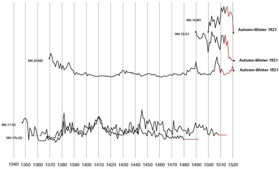 Figure 16. Summary of the chronology highlighted by the dendrochronology study. (F. Langenegger).
The results of this study are consistent with those of the first one carried out by F. Langenegger on the Mortella III wreck, which dated the felling of the trees used for its construction between 1517 and 1520 [4] (p. 26). The chronology highlighted by these studies, together with the archaeological evidence and textual documentation, leaves no doubt as to the identity of the wrecks, the Boscaina and the Ferrara, sunk in August 1527 in the historical context of the Seventh Italian War.
7. The Anchors
7.1. Description
Two iron anchors lay on the central tumulus of the Mortella II site. The East Anchor (F-MII-AE), known since the discovery of the wreck, is clearly visible in the middle of the site; it is preserved in all its iron parts, but the wooden stock is missing, destroyed by the fire set when ship was abandoned and/or by marine xylophages (Figure 17 and Figure 18). The West Anchor (F-MII-AW), discovered on the very first day of the 2021 campaign, lays 4 m westwards; it is the smallest, and is not completely preserved, missing the ring, the head, the wooden stock, and most of one arm (Figure 19 and Figure 20). The surviving part is broken into three fragments: at the fracture spots of the shank, it is possible to measure the concretions thickness, varying from 0.5 cm to 3.5 cm, and averaging 1.5 cm (see Table 3). This result confirms the concretion thickness estimates previously made for the Mortella III anchors, and it was applied to the two Mortella II anchors.
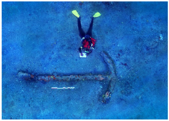
Figure 17.
The East anchor F-MII-AE. Photogrammetry: Stéphane Jamme.
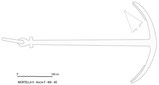
Figure 18.
The East Anchor F-MII-AE. Drawing: Fabrizio Ciacchella.
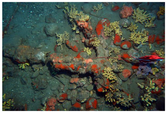
Figure 19.
The West Anchor F-MII-AW. Photo: Stéphane Jamme.
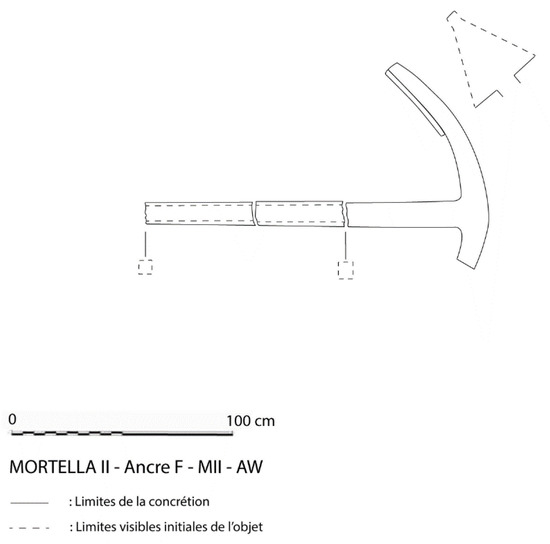
Figure 20.
The West Anchor F-MII-AW. Drawing: Fabrizio Ciacchella.

Table 3.
Concretion thickness measured at the fracture points of anchor F-MII-AW.
Missing the upper part of its shank, the original length of F-MII-AW is unknown, yet it is possible to estimate it. Based on the hypothesis that its proportions were similar to those of the other anchors of the Mortella wrecks, some ratios have been examined, between the shank length and: (a) arm’s length (from crown to tip); or (b) anchor’s beam (from tip to tip); or (c) shank maximum width. According to the calculations, the anchor original length was estimated at 255 ± 65 cm. The results related to (a) and (b) are almost identical (265–315 cm and 260–320 cm); on the contrary, the results related to (c) are very different, ranging from 190 to 225 cm. The latter range has no overlap with the other two: this means that F-MII-AW could not be similar to the other Mortella wreck anchors for all the proportions. Even if the overall range is quite broad, these estimates are important, because they can lead to a mass estimate, and finally to understanding the function of the anchor (see Section 7.3 and Section 7.4).
Two iron anchors are also present on the Mortella III wreck: the South Anchor (F-MIII-AS) and the West Anchor (F-MIII-AW), each missing the wooden stock but preserved in all the iron parts, covered with concretions whose thickness was previously estimated at 1.5 cm. 2 The dimensions, proportions, and morphological characteristics of the Mortella wreck anchors are shown in Table 4 for comparison.

Table 4.
Measurements, proportions, and morphology of the Mortella wreck anchors.
7.2. Morphological Comparison
The stock-anchors of the Mortella wrecks belong to the type often called ‘admiralty’ or sometimes ‘common admiralty’, to avoid confusion with the BritishAdmiralty types. Nevertheless, such a denomination does not seem appropriate, because this type of anchor appeared in the late 14th or early 15th century [23] (p. 111), three centuries before the British Admiralty started establishing the characteristics of the anchors to be used in the Navy [24] (pp. 54–55).
From a morphological point of view, the Mortella anchors are very similar: they all have a ring, an oval bulging head, the nuts on the same plane as the arms, the curved arms, and the triangular flukes. The angles between the shank and the arms (measured at the crown) have very little variance, within a range of 5° only, with small asymmetries of 1° to 4° between left and right angles, due to either imperfect forging or deformation that occurred during use. Other similarities seem to exist (the rounded crown and the presence of bills at the extremity of the arms), but they are difficult to ascertain because of concretions. On the contrary, marked morphologic differences are fewer. The top of the oval-shaped head is flat in one case, and cusped in another; the flukes have the form of a more or less elongated triangle: in half the cases the base (width) equals the height (length), while in the others it is smaller. The South Anchor of the Mortella III wreck has a rare characteristic, two pairs of nuts of rounded form. To date, such a feature has been found in only two other anchors: an isolated find in Bastia-Figajola (Corsica) and the smallest anchor of the late 16th century wreck of Sveti Pavao (Mljet I., Croatia) [23] (p. 114); [25] (pp. 61–62, 68). In the other Mortella anchors, the nuts are missing or their form is not visible because of concretions.
In order to move the comparison beyond the apparent morphology, it is useful to study the proportions between the different parts of the anchors, calculated under the estimated (or occasionally measured) concretion thickness. From this point of view, similarities consist of variations inside more or less broad ranges. The narrowest variance found concerns the proportion the between fluke length and arm length (the latter measured from the tip to crown): 0.45 ± 0.02, c. 3/7, corresponding to c. 1/2 if the arm length is measured from tip to throat. Other proportions have a greater variance, but in most cases they represent different simple fractions. The arm length (tip to crown) can be 1/4 or 1/3 of the shank length. As for ‘shank slenderness’, its maximum width at the lower end (or ‘big of the shank’) can be 1/30 or 1/25 of the shank length. As for ‘shank taper’, the minimum width at its upper end (or ‘small of the shank’) can be c. 1/2 or c. 2/3 of its maximum width at the ‘big of the shank’. Ring mid-diameter 3 can be 1/7, 1/8, or 1/9 of the shank length. These proportions suggest that, though standardization had not yet developed, anchorsmiths were following different but well defined designs. In particular, the fact that ring size related to shank length is not random contradicts Fournier, who in 1643 claimed that rings were made with ‘no order of magnitude’ (‘sans ordre de grandeur’) [26] (p. 43). At his time, in France, big anchors were not made in local workshops but were imported from Spain, Italy, and Holland [24] (pp. 72–73, 95–96): this may have augmented the ring size variability, giving to Fournier the impression that there was no rule. Mainwaring, in 1622, had a different opinion. According to him, ring diameter was equal to fluke length [24] (p. 51), [27] (pp. 91, 98). As is also shown by the Mortella anchors, the proportion of the latter to arm length had very little variation; on the contrary, the proportion between the arm length and shank length varied much more, and this determined the great variability of ring size compared to shank length.
7.3. Mass Estimation
It is possible to estimate the mass of an anchor by multiplying the iron density for its volume, calculated from dimensions after subtracting the concretion thickness. In the case of the broken shank of the Mortella II West Anchor (F-MII-AW), the thickness was measured wherever visible, and the average was calculated: 1.5 cm (see Table 3); the same was assumed for the other anchors of the Mortella wrecks. The estimated mass is c. 490 kg for F-MII-AE, c. 660 kg for F-MIII-AS, and c. 800 kg for F-MIII-AW (see Table 4). For the West Anchor of Mortella II (F-MII-AW), missing the upper part of the shank, two length estimates were considered (see Section 7.1.). The diameter of the missing ring was estimated to equal to fluke length, according to Mainwaring’s statement (see Section 7.2.). To estimate the ring thickness, the proportion mentioned in a French document of 1698 was used, the next available source from both a chronological and a geographical point of view (Archives Nationales, Fonds Marine, B3 102.40 [27] p.103–104). According to this, the circumference of the ring thickness was the same as the diameter of the ‘big of the shank’ (i.e., the shank maximum cross-section). Applied to F-MII-AW dimensions, the resulting ring mid-diameter is c. 39 cm, and its thickness 4 c. 3.6 cm. The estimated mass of F-MII-AW is c. 110 ÷ 150 kg (see Table 5).

Table 5.
Mass estimation of the anchors of the Mortella II wreck.
7.4. Functions of the Anchors
It is very difficult to assess the different functions of the anchors found on a wreck, unless a complete set has been found. Those of the Mortella wrecks represent a rare exception. Due to its large size, orientation, and central position, almost perfectly superimposed to the wreck’s axis, F-MII-AE has been interpreted as the heaviest anchor on board. 5 Called the ‘sheet anchor’, it was used in case of extreme danger only. On the contrary, anchor F-MII-AW, owing to its small size and estimated mass of c. 110–150 kg could only have been a ‘kedge anchor’ or ‘kedger’. The lightest onboard (not considering those of the ship’s boats, significantly lighter, usually four-armed grapnels) it was used to move a ship within a bay or upstream a river, after being transported on the ship’s boat to the desired place. In Genoa it was called ‘ancora pro tonezar’, and in Dalmatian Ragusa ‘ancora de andrivello’ [28] (pp. 485). According to documental sources, its mass was proportioned to the one of the sheet anchor, with a few differences related to time and place. As explicitly stated by the Ragusan Nicolò Sagri in the treatise Il Carteggiatore of 1571, it was 3/8 (0.375) of the sheet anchor [29] (pp. 140–142). In an example given in the Spanish treatise Instrucción Náutica of 1587, the mass of the kedger cable was 1/3 (0.333) of the one of the sheet anchor cable [30] (p. 306). The anchor masses were not given, but probably had the same proportions, as stated by Sagri in his abovementioned text. A Spanish treatise of c. 1632, the Diálogo entre un Vizcayno y un Montañes, mentions a ship with a sheet anchor of 2000 libras and two kedgers of 350 and 450 libras [31] (p. 188), whose mass ratios to the former are 0.175 and 0.225, respectively. The proportion between the mass of the Mortella II kedger and her presumed sheet anchor (F-MII-AW/F-MII-AE) is 0.22–0.31, according to the different estimates of the former. The higher figure (0.31) is practically identical to the proportion of the cables in the example given in the Spanish treatise Instrucción Náutica of 1587 (0.333) and is just a little lower than the proportion explicitly mentioned by the Ragusan treatise Il Carteggiatore of 1571 (0.375, see above). The lower figure (0.22) is identical to the proportion that can be calculated from an example given in the Spanish treatise Diálogo entre un Vizcayno y un Montañes of c. 1632. In both cases, the mass proportion between the kedger and the sheet anchor of the Mortella II ship sunk in 1527 seems to anticipate the Spanish use of the late 16th or the early 17th centuries [32] (pp. 51–52).
The anchors found on the Mortella III wreck had different functions. The only nautical text of the first half of the 16th century giving the example of a ship of known net tonnage and her anchors’ weight is the Spanish treatise Espejo de navegantes by Alonso de Chaves, c. 1537 [33] (ff. 60v-61r), dealing with a nao of 200 toneles (304 m3) and her set of anchors ranging from 7 to 11 quintales (322–506 kg). Expressed in Genoese measure units, such a ship capacity (net tonnage, i.e., the maximum volume loadable in the hold) was equivalent to 1145 salme generali di Sicilia of 0.2655 m3. According to the ‘mass to volume’ Genoese conversion factor of the time, 4 cantari/salma [4] (p. 102), it corresponded to 4580 cantari (218 t) of net deadweight (i.e., the maximum weight loadable in the ship—everywhere on board, not only in the hold). Assuming a linear proportion, the mass ratio between the sheet anchor and the ship net deadweight would be 0.23%. A recent study 6 has substantially confirmed the estimations of the Mortella III ship’s capacity and burden, setting her net tonnage to 2750 salme generali di Sicilia (730 m3) and her net deadweight to 11,000 Genoese cantari (525 t). This result stands right in the middle of the previous estimate range, from c. 10,000 to 11,900 cantari [2] (p. 142). If the Mortella III sheet anchor was proportioned in the same way as the mentioned example given by Chaves, its mass would have been 0.23% of the ship net deadweight, i.e., c. 1200 kg. According to the proportions mentioned in this paragraph, her kedger would weigh 0.225 to 0.333 times that mass, i.e., c. 270 to 400 kg. The estimated masses of the Mortella III anchors (F-MIII-AW, c. 800 kg; F-MIII-AS, c. 660 kg) are far from these figures. The ratio between the estimated masses of F-MIII-AW (c. 800 kg) and the theoretical sheet anchor (c. 1200 kg) is 0.66, practically identical to the one between the lightest and the heaviest anchors in Chaves’ example (7quintales/11quintales = 0.64). On the other hand, the ratio between the estimated masses of F-MIII-AS (c. 660 kg) and the theoretical sheet anchor (c. 1200 kg) is 0.55, very near to the proportion expressed by Sagri in 1571 for the ancora di pennello (anchor for ‘backing’, today sometimes ‘tandem anchor’), namely half the sheet anchor mass [29] (p. 141).
8. Ship Tonnage and Dimensions
If we accept the hypothesis that F-MII-AE was the sheet anchor of the Mortella II ship (see paragraph above), it is possible to compare its estimated mass (490 kg) with the sheet anchor of 11 quintales (506 kg), fitting the nao of 200 toneles (304 m3) of net tonnage described in the mentioned treatise Espejo de navegantes of c. 1537. According to these proportions, the Mortella II ship had a net tonnage of c. 300 m3, equivalent to c. 1100 salme generali di Sicilia, the units used at the time in Genoa. According to the Genoese ‘mass to volume’ conversion factor 4 cantari/salma [17] (p.102), this corresponded to a net deadweight of 4400 cantari (c. 210 metric tons). A ship of this size belonged to the typology that in Genoa was called barca, whose largest units were slightly smaller than navi, with 3000–8000 cantari of net deadweight (140–380 t), and a 23–27 m waterlength [16] (p. 189).
Starting from the estimated net tonnage of the Mortella II ship, it is possible to calculate her original dimensions by reversing the third formula for ship capacity explained by the Ragusan Nicolò Sagri in 1571 [29] (p. 141). This is the most appropriate to use for the Mortella ships, instead of other formulas of Venetian, Spanish, or English provenance, from both a chronologic and a metrological point of view. In fact, less than half a century separates it from the shipwrecks of Mortella; furthermore, it is the only one considering the measure units in use in the rest of Italy outside Venice, the cobitti (cbt) (cubits of 0.748 m, in Genoa called goa or guva), equivalent to three palmi di canna. The original version of the formula considered the three main ship dimensions measured inside the hold at full load waterline: length (L), beam (B, i.e., maximum width), and depth of hold (D). To obtain the net tonnage (NT) in salme generali di Sicilia (sgS), they were multiplied by each other, then reduced by one fourth, and finally by 5%:
NT[sgS] = (L[cbt] · B[cbt] · D[cbt] · 0.75[sgS/cbt3]) − 5%
A recent study transformed the measure units of many Renaissance tonnage formulas into metric decimal units, simplifying them into the product of the three main dimensions and a dimensionless coefficient. The latter is similar to the block coefficient, but refers to inside the hold, instead of outside the hull [14] (p. 179). After transformation, Sagri’s third formula becomes:
NT[m3] = L[m] · B[m] · D[m] · 0.461
In his manuscript, Sagri considered the following ship proportions as the most seaworthy: depth of hold as half the beam, and length as three times the beam, i.e., six times the depth of hold. In his opinion, these proportions were no longer followed in Ragusan shipyards of his time, but they were still the rule in Genoa, Portugal, and the Basque Country [29] (p. 123). These proportions also met the rule called ‘as-dos-tres’ in Spanish, where depth of hold is the unit, beam is twice the depth of hold, and length is three times beam. For ship with these proportions, it is possible to substitute L with 3B, and D with ½B; the formula is transformed into: 7
NT[m3] = B3[m3] · 0.692
B[m] = 3√(NT[m3]/0.692) = 3√(NT[m3])/0.8845
If the Mortella II ship had been built with these proportions, her main dimensions would be: 8
B = 7.6[m]; D = ½B = 3.8[m]; L = 3B = 22.8[m]
These figures are coherent with the dimensions of the Mortella II site from the SONAR image of 2005, as well as from the topography and photogrammetry of 2021.
It is possible to verify the coherence of these calculations by using the formula empirically determined by Gatti in 1999 for ships of the 17th century and first half of the following century [16] (p. 285), and modified by Ciacchella in 2022 for a ship of the first half of the 16th century [14] (pp. 188–192). According to this modified formula, net deadweight expressed in Genoese cantari (Gc) is equal to the product of the ship’s three main dimensions expressed in palmi di canna (pdc) divided by ten:
NDW[Gc] = L[pdc] · B[pdc] · D[pdc]/10[pdc3/Gc]
Applied to the Mortella II ship, 9 the resulting net deadweight (206 t) is practically identical to the one obtained from the parallel with the Espejo de navegantes (210 t, see above in this paragraph).
The lesser dimensions of the Mortella II wreck, compared with those of Mortella III, are coherent to the ordnance found, nearly half the amount of the latter (see Section 9.2.).
However, these results contrast with the interpretations of other finds. The trial trench excavated in 2021 at the limit of the preserved hull uncovered the assembly between several frames and two futtocks, interpreted as the first and second (named starting from the keel). In this case, the preserved hull would be narrower than the ship’s original beam, and ship size would be larger than that estimated above. The observed thickness of the hull planking (c. 10 cm) is similar to the one found in the Mortella III wreck, a much larger ship, and is much more than expected for a ship of such dimensions as Mortella II, unless her hull had two layers of planking (double planking).
9. The Ordnance
9.1. General Description
All the ordnance found on the Mortella II wreck, as well as on the Mortella III, belongs to the same typology of wrought iron port pieces, in Italian called bombarde in the strict sense. These guns consisted of a barrel (tromba), a breech chamber (mascolo in Italian, canono 10 in Latin), and a wooden stock or carriage (letto or fusto) (Figure 21). Barrels were cylindrical tubes open at both ends, which could be loaded from the rear (breech-loading). Usually their construction was similar to casks, made of long iron staves of trapezoidal cross-section held together by short cylindrical sleeves, reinforced with thick hoops (sometimes called ‘ribs’) overlapping the many sleeve seams. Alternatively, probably on smaller pieces, barrels could be made of two or three iron plates rolled up to form a tube, reinforced with sleeves and hoops such as those made of staves. Breech chambers were loaded with gunpowder; they could be made either of staves and hoops similarly to barrels, or a single piece of forged or cast iron. Wooden stocks were usually monoxyle, made of half a hollowed-out log reinforced with iron, to which barrels were tethered. A hole was present in the rear part, probably to drain the water mixed with vinegar said to be used to refresh guns when necessary.
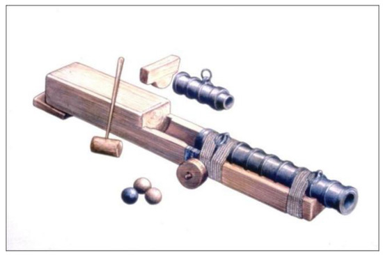
Figure 21.
Reconstruction of a port-piece with its wooden stock. Drawing: N. Biotti.
At the rear end, the wooden stock had a vertical extension; a wooden wedge was forced between it and the breech chamber to prevent the latter from being thrown backward while shooting and to increase the hold with the barrel. A pair of small wheels could be added below the front part of stocks to increase mobility; their diameter changed according to the placement on the ship and the height from deck to port. Pointing the gun was possible just by lifting its rear part with a wedge or a rack [30] (p. 123), [34], [15] (p. 228).
9.2. Number and Distribution of the Mortella Port pieces
A preliminary study of the Mortella wreck ordnance was conducted by Max Guérout, 11 to whom this author is greatly indebted. Sixteen barrels and thirteen breech chambers were found on the Mortella wrecks; their distribution is shown in Table 6.

Table 6.
Number and distribution of the Port pieces of the Mortella II and III wrecks.
Ordnance is concentrated at both extremities of each site and is absent midship. The distribution of barrels is similar in the two wrecks: two at the (presumed) bow of each site, and with the rest on the (presumed) stern: four at Mortella II, and eight at Mortella III. Four breech chambers were found at the stern of each wreck, four at the bow of Mortella III, and one at the bow of Mortella II.
9.3. Morphology
The morphological study of the Mortella barrels and breech chambers was difficult because of concretions: while for those outside the pieces it may seem reasonable to estimate the same thickness as the fractures spots of the Mortella II West Anchor, it would not be realistic for those inside, which seem to have grown much more, sometimes nearly filling the whole cavity of the guns and not allowing us to measure the ordnance’s original caliber. Visual examination confirmed the presence of hoops (that led to the identification of the guns as bombarde, port pieces) and, in some cases, of ‘handle’ rings connected to a hoop (Figure 22). Table 7 presents the dimensions and characteristics of the studied ordnance pieces of the Mortella wrecks.
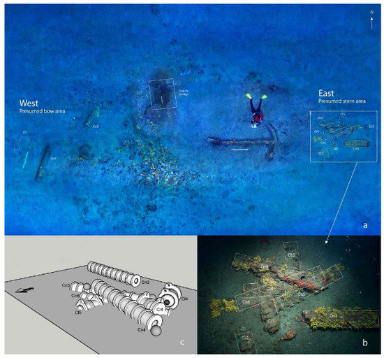
Figure 22.
Artillery layout on the Mortella II wreck. (a) General layout. (b) Artillery layout at eastward artillery layout. (c) Restoration of the eastward artillery layout. Photos: S. Jamme. Sketch: J. Guevara.

Table 7.
Characteristics of the Mortella wrecks’ ordnance.
Barrels (Figure 23 and Figure 24). During the Renaissance, gun size was usually measured by their weight, in Genoa expressed in cantari of 47.65 kg. Their length was very seldom mentioned; one of these rare descriptions comes from a Spanish document of 1505 attesting to the purchase of almost a hundred lombardas of 9 palmos and three 10 palmos [15] (p. 227). With only one exception (MII-CN4), the length of the studied Mortella barrels corresponds (in some cases exactly, in others nearly) to 6, or 8, or 9 Genoese palmi di canna of 24.8 cm.
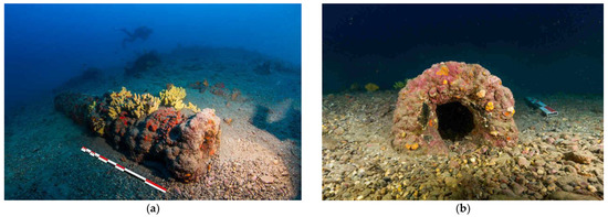
Figure 23.
Barrel MII-Cn1. (a) Side view. (b) Front view. Photos: Stéphane Jamme.
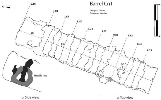
Figure 24.
Barrel MII-Cn1. (a) Side view. (b) Top view. Sketch: Jesús Guevara.
From a structural point of view, the uneven distribution of hoops and the large variance in the distance between them within individual barrels (range 0.04–0.15) within the single barrels suggest that, at the time, the design of wrought iron port pieces was not very accurate. However, the proportion between hoops average distance and barrel length has little variance (0.095 ± 15%; range 0.08–0.11), and the proportion between the barrel length and its external diameter, with one only exception (MII-C4), has less variance (5.65 ± 3%, range 5.5–5.8), showing that some sort of plan was followed when forging barrels. In the only exception (MII-C4, c. 132 cm, the shortest barrel), the ratio ‘length to external diameter’ is lower (4.3), making it the stoutest piece. It was either a piece of different proportions or part of a broken bigger gun, the rest of which is still to be discovered. Unfortunately, because of the massive growth of concretion inside the guns, it is not possible to calculate the ratio between the internal length (bore) and its diameter (caliber), an important parameter affecting the accuracy of shooting.
‘Handle’ rings were observed on a port piece of Mortella II (MII-CN1) and on half of those from Mortella III.
Breech chambers (Figure 25 and Figure 26). The presence of hoops on a few breech chambers of the Mortella wrecks suggests a structure similar to the barrels present on both sites, rather than made of solid iron; unfortunately in many cases they are too covered with sediments or encrustations to even detect the presence of hoops. ‘Handle’ rings were observed on a chamber of each of the Mortella wrecks. The breech-chamber MII-CL1, c. 70 cm long, is nearly 3 palmi di canna (74 cm) (Figure 25 and Figure 26). Its hoops are evenly distributed, and the ratio between their distance and chamber length (0.20, i.e., 1/5 of the length) is twice as the average one of the barrels (0.10, i.e., 1/10 of the length). This is strange enough as chambers had to resist the energy of the gunpowder explosion.
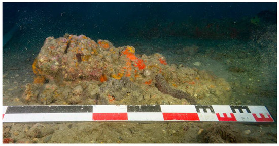
Figure 25.
Breech chamber MII-Cl1. Photo: Stéphane Jamme.
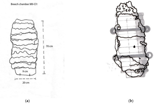
Figure 26.
(a) Breech chamber MII-Cl1. (b) Hypothesis of reconstruction. Diagram: Jesús Guevara.
The Mortella III breech chambers have the same length as the examined Mortella II one (MII-CL1), c. 70 cm. 12
9.4. Gun Shot
All the shot found on the Mortella wrecks are made of stone; their study is of great interest and can give information on their geographical provenance, as well as on port piece caliber. During the 2021 campaign, six stone shot were found at the Mortella II site (see Table 8 and Figure 27); another one had been previously recovered during the 2007 preliminary survey. They have different calibres: 21 cm, 17 cm, 15.8 cm, and 11.5 cm. Two of them have an irregular polyhedral form (minimum/maximum dimensions of 15/18 cm and 16/18 cm), as if they were being shaped by the crew during navigation, probably to make a shot of the same caliber as the 15.8 one. Petrologic analysis of the Mortella II stone shot is still in progress; to date, the only available result concerns a 15.8 cm shot weighing 5.7 kg, made of serpentinite, a hard siliceous metamorphic rock common on the shores of the Gulf of Genoa and in the Piedmont.

Table 8.
Stone shot recovered from the Mortella II site.
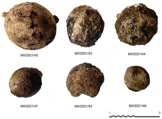
Figure 27.
Stone shot recovered from the Mortella II site. Photo: Arnaud Cazenave de la Roche.
Many stone shot were also found on the Mortella III wreck, in four different calibers. The most common are nearly twenty shot of 22–23 cm diameter, weighing 16–17 kg, nearly 50 Genoese libbre (15.9 kg), and made of serpentinite. A single shot of 15.8 cm and weighing 7 kg (exactly 22 libbre) is made of the same rock. Out of a dozen 12.5 cm shot weighing 1–1.5 kg, (3–5 libbre), seven are made of detrital sedimentary rocks, five of igneous volcanic rocks from Southern Italy, and one of metamorphic rock. A few 9.6 cm shot, weighing 1.3–2.3 kg, were found on the Mortella III wreck, as well as some irregular polyhedral stone shot undergoing shaping. 13
9.5. Discussion
Only wrought iron port pieces and their stone shot were found on both the Mortella wrecks, and neither swivel guns nor their lead shot. According to inventories of the time, they were surely present aboard; they may be still hidden under the sediment or, because of their light weight, they could have been easily removed, either taken away on the boats while the crew was abandoning ships or looted by sport divers in more recent times. Interpreting the absence of big bronze guns requires a reflection on the maritime laws regulating ordnance onboard Genoese ships of the Renaissance.
Though ordnance had appeared aboard Genoese ships since the late 14th century [35] (p. 90), the Statuto di Gazaria of 1403 contained no reference to it [36] (pp. 188–197). This subject appeared for the first time in Genoese maritime laws with the Statuto di Gazaria of 1441, which established different fittings according to ships net deadweight. Ships of 4000–5000 cantari (191–238 t) had just one bombarda, and those of 6000–7000 cantari (286–334 t) had three. Larger ships had different fittings in peacetime or in wartime: differences were much noticeable for crew and some fittings, including anchors, while for ordnance they were very slight and they did not concern every tonnage class. Ships of 8000–10,000 cantari (381–477 t) had four bombarde in wartime 14, those of 11,000 cantari (524 t) had four in peacetime or five in wartime, those of 12,000–13,000 cantari (572–619 t) always had five, those of 14,000–17,000 cantari (667–810 t) had five or six, those of 18,000–21,000 cantari (856–1000 t) always had eight [28] (pp. 466–487). In 1498, the Genoese decree Nova forma pro navibus imposed new rules for ships over 10,000 cantari (477 t). The new ordnance requirements consisted of two canoni de metalo of 23 and 27 cantari (bronze guns of 1096 and 1287 kg) shooting 50 Genoese libbre shot (15.9 kg), four bronze falconi weighing 7 cantari each (334 kg), and 35 iron bombarde of unspecified weight. The ammunitions were composed of 200 lead shot with an iron core for the ‘falconetti and other spingarde’ (small guns), a reserve of 4 cantari (190 kg) of lead probably for melting new shot, 60 shot for the canoni, and 700 shot of unspecified material ‘for the rest of the bombarde’. The last phrase suggests that in the number for the bombarde were also included some of the previously mentioned types of guns, probably the spingarde, as the falconetti were made of bronze. Swivel guns, not listed anywhere else, were probably included too. In fact, a ship inventory of 1493 written in Latin, at the paragraph ‘Bombardarum’ listed both port pieces and swivel guns: one bombarda magna and five passavolanti magni (six big port pieces in all), eight bombarde pro orlo, six bombarde a la frixe, two bombarde cum manico ferri (eight pieces for the gunwale, six pieces for the stern gunwale, and two with an iron handle, all of them swivel guns), plus thirty-two bombarde for the forecastle and the aftcastle. The inventory specified that all the ordnance had three breech chambers each (‘omnia cum … canonis tribus pro qualibet’), therefore they were all breech-loading pieces. A similar proportion is found in a Genoese document of 1495 reporting the inventory of a nave of Angelo Lomellino fitted with 53 bombarde and 161 breech-chambers [15] (pp. 227–234).
As for the Mortella II ship, should the proposed estimate of 4400 cantari of net deadweight (see Section 7) prove to be incorrect, it is nevertheless unlikely that a site of such dimensions could be of a ship over 10,000 cantari; therefore the Mortella II was not subject to the decree of 1498 and was not due to carry bronze ordnance.
On the other hand, the absence of bronze guns from the Mortella III site raises many questions. As we have seen (Section 7.4), based on the archaeological evidence, a few estimates have been proposed for her net deadweight, ranging from around 10,000 to 11,900 cantari. Being over 10,000 cantari, she was also due to carry bronze guns, yet they have not been found. Are they still under the sediment, waiting to be excavated, or were they looted by sport divers in the seventies, as rumors say? Was she over that limit, but sailing with reduced fittings (guns as well as anchors), just to be able to load a few tons more of grain? This could explain the incomplete set of anchors found. Was she really slightly over that limit and maybe slightly underestimated by some port officer or understated by her captain to pay less taxes? Did the archaeological interpretation slightly overestimate her dimensions? Did the used formulas slightly overestimate her tonnage?
As for the number of wrought iron port pieces, ships up to 10,000 cantari, not subject to the decree of 1498, could be expected to have still been subject to the previous laws, but this was not the case. According to the statute of 1441, ships of 4000–5000 cantari net deadweight (like Mortella II) had to carry a single bombarda, instead of the six found; those of 10,000–11,000 cantari (like Mortella III) had to carry five bombarde, instead of the ten found. The amount of ordnance found on the Mortella II wreck was required of ships of 14,000–17,000 cantari, three to four times her estimated net deadweight; the amount found on the Mortella III wreck was never reached by the requirements of the 1441 statute, not even for the largest ships mentioned (21,000 cantari) and nearly twice her estimated net deadweight. This means that, as for ordnance, at the time of the sinking of the two Mortella ships, habits had become much more demanding than the requirements of the Statute di Gazaria of 1441.
Given the similarities in the ordnance distribution of the two wrecks, it is possible to attempt a hypothesis. The two pieces at the bow could have been the bow chasers, situated inside the forecastle and aiming forward. Those at the stern were probably situated inside the aftcastle; two of them, the stern chasers, aiming backward, the rest aiming at both sides: one by each side of the Mortella II ship, and three by each side for the Mortella III one. A similar distribution is shown in the naval iconography of the 16th century; for instance, in a fresco by Giovanni Battista and Stefano Perolli, portraying a ship of the Charles V expedition to Algiers (1541) 15, two escape guns are visible through the transom ports (one on each side of the ship symmetry axis), and eight through those at the side of the aftcastle; no guns are visible at the side of the forecastle, while the bow is not visible. Larger ships in the same fresco also have guns amidship, arranged in batteries (Figure 28). The total absence of guns in the middle of the Mortella sites is coherent with the tonnage estimates of the two ships, a mid-size barca of 4400 cantari and a mid-size nave of 11,000 cantari of net deadweight, compared to the largest naval units that, as early as 1441, reached the 21,000 cantari mentioned in the statute of Gazaria.
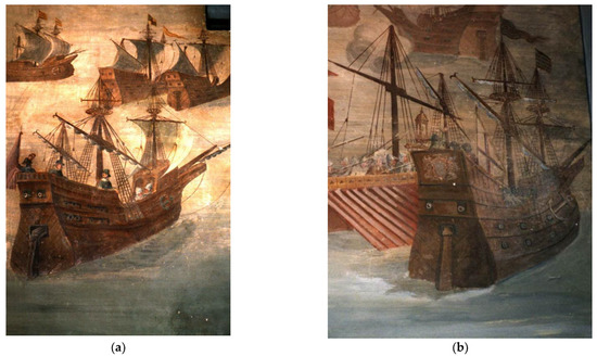
Figure 28.
Frescos by Giovanni Battista and Stefano Perolli, c. 1570. Castle of Álvaro de Bazán, Maritime Museum of Viso del Marqués, Spain. (a) Nave of small dimensions with an arrangement of her artillery similar to the one of the Mortella II wreck. (b) Nave of a greater tonnage with two batteries with port-pieces arranged all along her starboard side. Photos: Arnaud Cazenave de la Roche.
As we have seen, the habits of the time involved three breech chambers for every breech loading piece, so they had to be eighteen on the Mortella II ship, and thirty on the Mortella III one: more than one dozen of the former’s are missing, and almost two dozen from the latter, probably still lying under the sediment.
According to the mentioned documents, onboard Genoese ships of the time, there were several hundred shot; therefore, most of those of the Mortella wrecks still have to be under the sediment. The findings from both wrecks only include stone shot, and none of the small lead and iron type mentioned in the Genoese laws and inventories of the time (see above in this paragraph). They are present in a few different calibers: 21 cm, 17 cm, 15.8 cm, and 11.5 cm for the Mortella II wreck; 22–23 cm, 15.8 cm, 12.5 cm, and 9.6 cm. At the time, shot size was defined from their weight measured in Genoese libbre of 0.318 kg; indeed, the weight of many of the shot found on the Mortella wrecks corresponds to multiples of these units (see Section 9.4).
Commenting on his own transcription of the Nova forma pro navibus of 1498, D’Albertis interpreted the phrase ‘petre per li canoni de varena. LX.’ as sixty shot for the canoni, made of stone from Varena, near Genova-Sestri, where he stated that a local quarry provided hard and heavy rocks fit for gun shot. The only canoni mentioned in the decree fired shot of 50 libbre, 15.9 kg [17] (pp. 233–234). Nowadays a similar toponym (Varenna) designates a nearby creek and its valley, rich in serpentinite. The 22–23 cm shot made of this rock found on the Mortella III could well be the 50 libbre shot from the Varenna valley mentioned in the decree of 1498. The valley reaches the sea very near the ancient borders of the city of Genoa and inside today’s borders; therefore, the valley was the source of this hard rock nearest to Genoa.
Half a dozen 12.5 cm shot found on the Mortella III site are made of igneous volcanic rocks typical of explosive eruptions, similar to those of the Vesuvio or the Monte Somma near Naples. 13 This demonstrates that shot could be made out of rocks purchased abroad and shaped onboard, as suggested by a few polyhedral irregular shot from both wrecks.
10. Conclusions
This preliminary excavation of the Mortella II wreck proved delicate due to the depth of the site (47 m). It represented both a technical and logistical challenge for our team. Despite these constraints, the operation reported in this article was particularly fruitful. The information gathered both on the architectural remains and on the artefacts, mainly represented by anchors, artillery, and ceramics, made this first investigation very rich.
10.1. Naval Architecture and the Study of Wood
The architectural remains revealed a carvel built oak framework. The dendrochronology study concluded that the trees used for the construction were felled in the autumn–winter of 1521. The wood pieces uncovered appeared to be frames composed of two joined timbers, interpreted as first- and second-futtocks. Two clamps notched on the frames overlap the assembly of the futtocks. The remains extend over a length of approximately 25 m along a longitudinal axis of 255–75°. Evidence suggests that the stern is located eastward and the bow westward.
From an architectural point of view, the most striking aspect of the hull remains is the arrangement of the first-futtocks in pairs, i.e., in a double layout. We know of no similar case in 16th century shipbuilding. This arrangement differs from those of the Mortella III, Lomellina, and Calvi I wrecks, which were provided with single first-futtocks. Nor can it be compared with the double frame structures that appeared in shipbuilding in the 18th century, which were very different in nature.
10.2. The Anchors and the Estimates of the Mortella II Ship Tonnage and Dimensions
Two iron anchors were observed at the Mortella II site: a large one of 3.95 × 2.16 m, interpreted as the sheet anchor, and a small broken one, whose original dimensions were estimated at 2.55 × 1.41 m, interpreted as a kedge anchor. These two anchors were methodologically studied, combining echographic (SONAR) imagery, bathymetric/photogrammetric, and direct observations, on the one hand, and anchor/tonnage proportions, on the other, based on the hypothesis that the larger one was the sheet anchor. This latter aspect is particularly interesting because, as a result of recent research [32] (pp. 51–52), it leads the study of anchors beyond the classic morpho-chronological analysis. This study provides valuable information on the proportions between sheet anchor mass and ship tonnage of Genoese, Ragusan, and Spanish ships of the Renaissance, thus leading to a first approach to gauge a ship’s capacity based on the characteristics of the anchors on board, when the sheet anchor is identified. In the case of the Mortella II wreck, the net tonnage was thus evaluated at c. 1100 salme generali di Sicilia, i.e., c. 300 m3, which corresponds to a net deadweight of c. 4400 cantari di Genova, i.e., c. 210 metric tons. This in turn allowed us to estimate the ship dimensions, based on reversing the calculation method expressed by the Ragusan author Nicolò Sagri in 1571. The resulting profile is a small merchantman with a length of 22.80 m, a beam of 7.60 m, and a depth of hold of 3.80 m (all measurements inside the hold at second deck, corresponding to a full load waterline). Although these dimensions are coherent with those observed on the site through all the described methodologies, the results of this analysis, which are the product of a theoretical approach, must be taken with caution and will require verification of the archaeological evidence; they nevertheless confirm the visual impression that the Mortella II ship was smaller than that of the Mortella III (37 m estimated overall length).
10.3. The Ordnance
The ordnance observed at the site consists of wrought-iron port-pieces (bombarde) associated with stone shot. Their typology is similar to that of the Mortella III wreck and also to other wrecks of the period, both of Mediterranean tradition, such as the Lomellina (1516, Villefranche-sur-Mer), and of Atlantic tradition, such as the Mary Rose (1545, Portsmouth).
The distribution of this artillery at the site is similar to that observed for the Mortella III wreck: two tubes are arranged in the supposed bow area and four others in the supposed stern area. No artillery was found midship. This distribution makes it possible to speculate the ordnance arrangement onboard the navi.
Finally, a comparison between the Genoese maritime laws of the time and the estimated net deadweight of the Mortella II ship shows that she was too small to be subject to the decree Nova forma pro navibus of 1498, which regulated the fittings of ships over 10,000 cantari, ordnance included. On the other hand, she was fitted with much more iron artillery than required for ships of her size by the previous law, the Statuto di Gazaria of 1441.
10.4. The Ceramics
The quality of the ceramics found on the Mortella II wreck is one of the archaeological highlights of the campaign. Although their preliminary study by Marco Milanese (University of Sassari) is published in a separate article in this journal, it is worth mentioning them in the conclusion of this article. The ceramics recovered are ‘rare and exceptional’ from a double point of view:
- -
- First, the many fragments found and the several artefacts that it was possible to reconstruct—some of which are almost complete, essentially majolica from Montelupo with a large number of decorations—have unparalleled relevance and offer the prospect of substantial progress in the knowledge of a class of ceramics that is very important for the Mediterranean archaeology of the late Middle Ages and early modern period.
- -
- Second, the association of these majolica wares with a precisely circumscribed chronological context offers a unique possibility for a major advance in the redefinition of the traditionally accepted chronologies for this class of ceramics.
10.5. The Contribution of the Mortella Wrecks to the Knowledge of Mediterranean Shipbuilding during the Renaissance
This first excavation of the Mortella II wreck marks the end of a step of a study program initiated in 2010 with the start of the excavation of the Mortella III wreck. This latest operation allows us to link these two wrecks that share the same history and many characteristics, particularly architectural, but which also differ in certain aspects. From an architectural point of view, it also contributes to the constitution of a corpus of wrecks of the Mediterranean building tradition, with the creation of a first documentary base for this nautical area, which includes information from other wrecks such as the Lomellina and Calvi I, already mentioned. Other wrecks of high archaeological potential should be gathered in this corpus. Among them, let us mention:
- -
- Delta 2 wreck (San Giorgio, 1587, Cadiz, Spain), a Genoese nave [32,37]
- -
- Ribadeo 1 wreck (Santiago de Galicia, 1597, Spain), a Ragusan warship [38,39]
- -
- Sveti Pavao wreck (late 16th c., Mljet I., Croatia), a Venetian ship [40]
- -
- Gnalic wreck (Gagliana Grossa, 1583, Croatia), a Venetian ship
- -
- Sudurad wreck (Santo Hieronimo, 1576, Sipan I., Croatia), a Ragusan ship
Thus, this first assessment of the Mortella II site enriches our still incomplete knowledge of Mediterranean—and particularly Genoese—shipbuilding and Renaissance material culture. It is clear, however, that this operation remains a preliminary approach to the wreck and that a full archaeological excavation will be necessary to resolve the many questions raised and to achieve a thorough knowledge of the ship and her artefacts. Nevertheless, already, together with the documentation of the Mortella III wreck and those previously mentioned, it offers the prospect of participating in sketching out, for the first time, an outline of Mediterranean Renaissance technical culture, as was done for the Atlantic from the late 1980s with the emergence of ‘Ibero-Atlantic’ shipbuilding [41,42,43]. However, it is important to add that this corpus offers a representation of the western Mediterranean and mainly of Italian shipbuilding and that, in a second stage, the integration of Muslim shipbuilding will be necessary, to obtain a complete vision of the structure of shipbuilding in this nautical area.


Table 9.
Technical terms mentioned in the article.
Table 9.
Technical terms mentioned in the article.
| Arm | Part of the anchor designated to penetrate into the sea bottom to hold the ship in her position. |
| Barrel | The metal tube of a gun, through which the shot is discharged. |
| Beam, maximum breadth | The measure of breadth to the outside of the frames at the ship’s widest point at the level of the main deck. |
| Bilge clamp | A thick ceiling strake placed upon the scarves joining the end of the floor and first futtocks timber, just inboard of the sill. |
| Bill | The extremity of an anchor arm, when it is left not covered by a fluke welded in sub-terminal position. |
| Bore | The main cavity of a gun. |
| Breech chamber | The rear part of a breech loading gun, which contained the powder and was removed after each shot, to reload. |
| Breech loading, Muzzle loading | Two different types of gun loading, from the rear or the front, respectively. |
| Caliber | The diameter of a shot (the internal cavity or bore was slightly larger, to prevent friction between the shot and the internal gun wall). |
| Carvel construction | Shipbuilding technique of Mediterranean origin based on a layout of the planks edge to edge, without connection or overlap between them. Waterproofing was achieved by the natural swelling of the wood in contact with water, whose edges were provided with caulking. |
| Clamp | Thick ceiling timbers, also called foot-wales, used to reinforce the longitudinal structure of the hull in general. They are located on the joints of the floors to the first futtocks. The bilge clamps are located next to the sill, and the shelf clamps are used to support the decks. |
| Crown | The inferior, convex part of an anchor, where the two arms are welded to the shank |
| First-futtock, second-futtocks | The first-futtock is the frame component attached on each side of the floor timbers. Its other end is attached to the second-futtock |
| Floor-timber | Frame timber that crosses the keel, stem, or stern knee. Its ends are attached to the extremities of the first-futtocks. |
| Fluke | A flat and broad iron element welded in the lateral part of the anchor arm, in order to increase hold when penetrating into soft bottoms (mud, silt, lime, sand). |
| Foot wale | Thick ceiling strake, also named clamp, overlapping the assembly of the floor timber and the first futtock. |
| Frame | A set of longitudinally assembled timbers that constitute the transverse structure of a ship’s hull. They are arranged on the upper face of the keel. On their upper face, a longitudinal timber named a keelson is notched on them. Each frame is composed of a central piece, the floor-timber, jointed in the continuity of its port and starboard branches with pieces called first-futtocks. In France, the frames of a vessel of ‘premier rang’ (first rate) were composed of six futtocks. The last futtock was called the top-timber. |
| Head | The upper extremity of an anchor, where a hole for a large ring was present. |
| Net deadweight | The maximum weight that can be loaded on a ship without compromising its safety during navigation. In Italy, this was regulated by law since at least the 13th century. It does not depend on the volumes dedicated to merchandises. |
| Net tonnage | The volume of a ship hold, and consequently of the merchandise the can be loaded in it. |
| Nuts | Small iron expansions present in the upper part of the anchor, to increase the hold of the wooden stock to the iron shank. In the 16th century they were oriented on the same plane as the arms. |
| Planking, Hull planking | A set of planks, i.e., strakes of which the hull of a ship is made up. The hull planking is fixed on the outside of the frames. |
| Port piece | Artillery piece mounted on a wooden stock or carriage designated to shoot through a hole (called a gunport) in the ship side. |
| Ring | A large iron structure of the same form passing through a hole in the head of the anchor, to which was connected the anchor cable. |
| Room and space | Expression used in the description of the sequence of frames: ‘room’ is the part occupied by frame width, while ‘space’ is the distance between two next frames (i.e., the empty space between them). |
| Scarf | A kind of carpentry joint aiming to join two timbers by means of an oblique surface. Scarves can have different orientations (horizontal or vertical) and geometries (plain, flat, nibbed, under-squinted, tabled, keyed, etc.). Besides scarves, other kinds of carpentry joints exist: butts, laps, and half laps. |
| Shank | The straight, longest iron element of an anchor, connecting the ring and the arms. |
| Stock | Of anchor: a wooden structure made of two timbers, fixed to the upper part of an anchor and oriented perpendicularly to the arm; its function was to lay parallel to the sea floor in order to have arms perpendicular to the latter. Of artillery: a wooden structure on which a port piece rests. |
| Swivel gun | Usually a small gun fixed on a swivel so that it can be rotated horizontally and vertically. Onboard ships they were mounted on the gunwale or over the fore- and aftcastle. |
| Throat | The concave angle between the shank and each arm. |

Table 10.
Measure units mentioned in the text.
Table 10.
Measure units mentioned in the text.
| Italy | Spain | |||
|---|---|---|---|---|
| mass | libbra di Genova | 0.318 kg | ||
| cantaro di Genova (= 150 libbre) | 47.650 kg | quintal | 46.009 kg | |
| volume | salma generale di Sicilia | 0.2655 m3 | tonel (tonel macho) | 1.521 m3 |
| length | palmo di canna | 0.2478 m | ||
| cobitto (in Genoa: guva, goa) = 3 palmi di canna | 0.7432 m | |||
Author Contributions
A.C.d.l.R.: Conceptualization, Data Curation, Formal Analysis, Funding Acquisition, Investigation, Methodology, Project Administration, Supervision, Validation, Visualization, Writing—Original Draft Preparation, Writing—Review Editing. F.C.: Conceptualization, Data Curation, Formal Analysis, Investigation, Methodology, Supervision, Validation, Visualization, Writing—Original Draft Preparation, Writing—Review Editing. All authors have read and agreed to the published version of the manuscript.
Funding
This research was financially supported by The European Union’s Horizon 2020 research and innovation programme: grant agreement nº 843337 ‘ModernShip Project: The structures of the Early Modern Mediterranean shipbuilding’. The Spanish National Research Council (CSIC) through its Proyectos Intramurales de Arqueología en el Exterior Fund, PIAR (Intramural Archaeology Projects Abroad). The French Ministry of Culture through its Underwater Archaeology Department (DRASSM). The Collectivité de Corse, CdC (Corsica Government, France).
Institutional Review Board Statement
Not applicable.
Informed Consent Statement
Not applicable.
Data Availability Statement
Excavation reports from the Mortella wrecks contain the entire data set of this research. They are available online: https://csic.academia.edu/ArnaudCazenavedelaRoche/Excavations-reports (accessed on 15 January 2023).
Acknowledgments
The excavation of the Mortella II wreck has been possible thanks to the financial support of the European Union, the DRASSM (Department for Underwater Archaeological Research, French Ministry of Culture), the Government of Corsica (Collectivité de Corse, CdC), the Center for Nautical Archaeology Research (CEAN), the Spanish National Research Council–CSIC. The collaboration of Ana Crespo Solana (CSIC) and the ForSEAdiscovery consortium, Brandon Mason and the Maritime Archaeology Trust (MAT, UK), Fabien Langenegger and the laboratory of dendrochronology of OPAN (Neuchâtel Department of Archaeology, Switzerland), Marco Milanese (University of Sassari), Marta Moreno (CSIC), Leonor Peña (CSIC), Max Guérout (GRAN) and Sorbonne Université (FED 4124), the University of Genoa, the University of Corsica Pasquale Paoli, Aingurak (Jesús Guevara), Aquanaute (Stéphane Jamme) and the city of Saint-Florent. The authors would also like to warmly thank Gianni Ridella for his scientific contribution to this article, as well as the scientific and technical collaborators to the Mortella project, and the team of archaeologists and technical divers that made the excavation possible.
Conflicts of Interest
The authors declare no conflict of interest. The funders had no role in the design of the study; in the collection, analyses, or interpretation of data; in the writing of the manuscript; or in the decision to publish the results.
Notes
| 1 | |
| 2 | Ciacchella F., Etude de l’ancre sud, in Cazenave de la Roche A., Fouille annuelle programmée de l’épave de la Mortella III (St. Floent, Haute Corse—Rapport de Fouille, campagne 2019, p. 37,unpublished document submitted to the Département des Recherches en Archéologie Subaquatique et Sous-Marine (DRASSM). |
| 3 | Ring mid-diameter is the average of external and internal diameters, measured where concretions are thinner. |
| 4 | At the time of this document (end of 17th century), anchors shank had a chamfered, octagonal cross-section, which was assimilated to a circumference when giving its main dimension as a ‘diameter’. As for F-MII-AW, the rectangular cross section of the broken shank is clearly visible at the fracture spots; in this case the diameter could be assimilated to its maximum dimension, the diagonal of the rectangle. It can be calculated from the ‘big of the shank’ dimensions, after subtracting the average concretion thickness (1.5 cm); in this case, ring thickness would be 11.4 cm/3.14 = 3.6 cm. |
| 5 | Votruba, Gregory, Iron Anchors and Mooring in the Ancient Mediterranean (until ca. 1500 CE), unpublished Ph.D. thesis, Wolfson College, University of Oxford, 2014, pp. 39–40. |
| 6 | Ciacchella Fabrizio, ‘Estimation du tonnage et dimensions du navire de la Mortella III’, in Cazenave de la Roche, Arnaud, Sondage de l’épave de la Mortella II Saint-Florent, Haute-Corse)—Rapport d’opérations 2021, unpublished document submitted to the French Départment des Recherches en Archéologie Subaquatique et Sous-Marines—DRASSM, p. 148–150. |
| 7 | For ships of such proportions, in Sagri’s third formula it is possible to substitute L with 3B, and D with ½B: NT[m3] = L[m] · B[m] · D[m] · 0.461 = 3B[m] · B[m] · ½B[m] · 0.461 = B3[m3] · 0.692. B[m] = 3√(NT[m3]/0.692). |
| 8 | In this case, the formula is solved as follows: B[m] = 3√(300[m3] / 0.692) = 7.6[m]. |
| 9 | After transforming the calculated main dimensions of the Mortella II ship into palmi di canna of 0.248 m, Gatti’s formula modified by Ciacchella becomes: NDW[Gc] = 92[pdc] · 30.66[pdc] · 15.33[pdc]/10[pdc3/Gc] = 4324[Gc]. NDW[t] = NDW[Gc] · 0,04765[t/Gc] = 206[t]. |
| 10 | ‘Canono’ is quite a confusing term, as it was used to designate breech chambers, as well as big bronze muzzle loading guns. |
| 11 | Guérout, M., 2010, Étude de l’artillerie de l’épave de Mortella III’, in Cazenave de la Roche et al., unpublished report of the 2010 campaign submitted to the French Département pour les Recherches Subaquatiques et Sous-Marines (DRASSM), pp. 59–57. |
| 12 | Cazenave de la Roche et al. 2019, Rapport de fouille annuelle programmée de l’épave de la Mortella III, campagne 2019, unpublished report submitted to the French Département pour les Recherches Subaquatiques et Sous-Marines (DRASSM), p. 59. |
| 13 | Gendron, F., Étude du mobilier lithique, in Cazenave de la Roche, A. et al., Rapport de fouille annuelle programmée du site de la Mortella III, campagne 2013, unpublished report submitted to the French Département pour les Recherches Subaquatiques et Sous-Marines (DRASSM), 2013, pp. 118–146. |
| 14 | The Statute of Gazaria of 1441 does not specify the number of the artillery pieces in peacetime. |
| 15 | Giovanni Battista and Stefano Perolli were two Italian painters who worked in Genoa as well as in Spain. They painted the frescoes of the Charles V’s Admiral Alvaro de Bazán’s castle (Viso del Marqués, Spain) in the 1570’s. |
References
- Cazenave de la Roche, A. The Renaissance shipwrecks of the Saint-Florent bay (Mortella II and III) two sites of a high archaeological potential in Corsica (France). Int. J. Naut. Archaeol. 2011, 40, 69–86. [Google Scholar]
- Cazenave de la Roche, A. The Mortella III Wreck: A Spotlight on Mediterranean Shipbuilding of the 16th Century; British Archaeology Report–BAR Publishing: Oxford, UK, 2020. [Google Scholar]
- Cazenave de la Roche, A. L’épave de la Mortella III (Saint-Florent, Haute-Corse): Un Eclairage sur la Construction Navale au XVIème Siècle en Méditerranée; Archéologie Moderne et Contemporaine 08; Editions Mergoil: Drémil-Lafage, France, 2021. [Google Scholar]
- Cazenave de la Roche, A.; Ciacchella, F.; Guérout, M.; Langenegger, F.; Milanese, M.; Crespo Solana, A. Review of the Research Programme on the Mortella III Wreck (2010–2020, Corsica, France): A Contribution to the Knowledge of the Mediterranean Naval Architecture and Material Culture of the Renaissance. In Open Research Europe ORE, 2022, 2:6. Available online: https://doi.org/10.12688/openreseurope.13942.1 (accessed on 11 January 2022).
- Crespo Solana, A. ForSEAdiscovery: Génesis y marco histórico-metodológico de un proyecto interdisciplinar en Humanidades. In A Gestão dos Recurso Florestais Portugueses na Construção Naval da Idade Moderna: História e Arqueologia; Varela Gomes, R., Varela Gomes, M., Eds.; Libros POrtico: Lisboa, Portugal, 2016; pp. 1–14. [Google Scholar]
- Crespo Solana, A.; Nayling, N.; García González, I. ForSEADiscovery: Forest Resources for Iberian Empires: Ecology and Globalization in the Age of Discovery, 16th–18th Centuries (PITN-2013-GA607545) Marie Curie Programme; Consejo Superior de Investigaciones Científicas: Madrid, Spain, 2014. [Google Scholar]
- Giustiniani, A. Castigatissimi Annali Con la Loro Copiosa Tavola Della Eccelsa et Illustrissima Repubblica di Genova; c.1537; Omnisys: Cambridge, MA, USA, 1990. [Google Scholar]
- Giovio, P. Histoires Sur Les Choses Faictes et Avenues de Son Temps en Toutes Les Parties du Monde; Guillaume Roville: Lyon, France, 1552; Volume 2. [Google Scholar]
- Lane, F. Naval Architecture about 1550; Mariners’ Mirror: Oxfordshire, UK, 1934; Volume 20, pp. 24–49. [Google Scholar]
- Long, P.; Mc Gee, D. The Book of Michael of Rhodes a Fifteenth-Century Maritime Manuscript; MIT Press: Cambridge, MA, USA, 2009. [Google Scholar]
- Zorzi Trombetta da Modon (c. 1444), Libro de Navegar. Manuscript of the British Library, London, Cotton ms. Titus A XXVI. Manuscript partially translated by R. Anderson. In Italian Naval Architecture about 15th Century; Mariner’s Mirror: Oxfordshire, UK, 1925; Volume 11, pp. 135–163.
- Teodoro de Nicolò, Instructione sul Modo di Fabricare Galere, Manuscript of the Biblioteca Nazionale Marciana di Venezia, Manoscritti italiani, c. 1550, cl. IV cod. XXVI (5131).
- Sagri, N. Il Carteggiatore, Manuscript n°31951SA0111372C, TC Wilson Library, U. de Minneapolis, Transcribed in Dell’Osa, D., Il Carteggiatore di Nicolò Sagri; Francoangeli: Milan, Italy, 2010. [Google Scholar]
- Cazenave de la Roche, A.; Ciacchella, F.; Hormaechea, C. An insight into Mediterranean naval architecture in the sixteenth century through the texts of Nicolò Sagri (1538–1571). A comparative perspective with Ibero-Atlantic shipbuilding. In Chapter 7 of the Book Heritage and the Sea: Maritime History and Archaeology of the Global Iberian World (16th–18th Centuries); Crespo Solana, A., Castro, F., Nayling, N., Eds.; Springer Publishing: New York, NY, USA, 2022; pp. 147–197. [Google Scholar]
- D’Albertis, E. Le Costruzioni Navali e L’arte Della Navigazione al Tempo di Cristoforo Colombo; Tipografia Regio Istituto Sordo-Muti: Genova, Italy, 1893. [Google Scholar]
- Gatti, L. Navi e Cantieri Della Repubblica di Genova (Secoli XVI–XVIII); Brigati Editore: Genova, Italy, 1999. [Google Scholar]
- Borghesi, V.; Calegari, M. La nave Bertorota (1547–1561). In Miscellanea Storica Ligure, Guerra e Commercio Nell’evoluzione Della Marina Genovese Tra XV e XVII Secolo; Univeristà di Genova, Istituto di Storia Moderna e Contemporanea: Genova, Italy, 1970; pp. 93–116. [Google Scholar]
- Calegari, M. Navi e barche a Genova tra il XV e il XVI secolo. In Miscellanea Storica Ligure, I (Guerra e Commercio Nell’evoluzione della Marina Genovese tra XV e XVII Secolo; Universita di Genova: Genova, Italy, 1970; p. 21. [Google Scholar]
- Ciciliot, F. Le superbe navi. Cantieri e tipologie navali liguri medievali. In Società Savonese di Storia Patria; Atti e Memorie, Nuova Serie: Savona, Italy, 2005; Volume XLI. [Google Scholar]
- Guérout, M.; Rieth, E.; Gassend, J.M. Le Navire Génois de Villefranche, un Naufrage de 1516? Archaeonautica, CNRS: Columbus, OH, USA, 1989; Volume 9. [Google Scholar]
- French Ministry of Culture. Available online: https://www.culture.gouv.fr/Media/Thematiques/Archeologie/Fichier-PDF/Drassm/Drassm_guide_conservation (accessed on 11 June 2020).
- Villié, P. L’épave Calvi 1. In Cahiers d’Archéologie Subaquatique; CAS: Columbus, OH, USA, 1990; Volume 9, pp. 83–130. [Google Scholar]
- Ciacchella, F. The evolution of nuts and other fixation systems of wooden stocks to iron anchors. In Archeologia Postmedievale; Edizioni del Giglio: Sesto Fiorentino, Italy, 2022; Volume 25, pp. 107–131. [Google Scholar]
- Curryer, B.N. Anchors–An Illustrated History; Chatam Publishing: London, UK, 1999. [Google Scholar]
- Ciacchella, F. Ancore Della Prima età Moderna dal Mare Adriatico Croato, uno Studio Analitico Della Morfologia e Delle Proporzioni. In Facta; Fabrizio Serra Editore: Pisa/Roma, Italy, 2015; Volume 7, pp. 55–90. [Google Scholar]
- Fournier, G. L’Hydrographie; Michel Soly Editeur: Paris, France, 1643. [Google Scholar]
- Gay, J. Six Millénaires D’histoire des Ancres; Presses de l’Université de Paris-Sorbonne: Paris, France, 1997. [Google Scholar]
- Pardessus, J.M. Collection de Lois Maritimes Antérieures au XVIII Siècle; Imprimérie Royale: Paris, France, 1837; Volume 4. [Google Scholar]
- Dell’Osa, D. Il Carteggiatore di Nicolò Sagri; FrancoAngeli: Milano, Italy, 2010. [Google Scholar]
- García de Palacio, D. Instrucción Náutica; México, 1587. Ed.; Museo Naval: Madrid, Spain, 1993. [Google Scholar]
- Vicente Maroto, I. Diálogo Entre un Vizcayno y un Montañés Sobre la Fábrica de Navíos–Estudio y Transcripción del Texto; Ediciones Universidad de Salamanca: Salamanca, Spain, 1998. [Google Scholar]
- Ridella, R.G.; Alzaga García, M.; Enriquéz Macias, G.; Gallardo Abárzuza, M.; Higueras-Milena Castellano, J.M.; Ciacchella, F. The Cadiz-Delta II wreck: The ‘San Giorgio’, a Genoese merchantman sunk by Francis Drake in 1587. In Archeologia Postmedievale: Società, Ambiente, Produzione; All’Insegna del Giglio: Florence, Italy, 2016; Volume 20, pp. 11–63. [Google Scholar]
- Alonso de Chaves, Espejo de Navegantes. c.1537. Editors P. Castañeda, M. Cuesta and P.Hernández, I. G. España, Madrid. 1977. Available online: https://bibliotecadigital.rah.es/es/consulta/registro.do?control=RAH20120001336 (accessed on 15 January 2023).
- Ridella, R.G. Genoese Ordnance Aboard Galley and Merchantmen in the 16th Century, in Beltrame Carlo, Ridella, Renato Gianni, Ships and Guns: The Sea Ordnance in Venice and Europe between 15th and 17th Centuries; Academia: Venezia, Italy, 2010. [Google Scholar]
- Campodonico, P. La Marineria Genovese dal Medioevo all’Unità d’Italia; Fabbri Editori: Milano, Italy, 1989. [Google Scholar]
- Vitale, V. Le Fonti del Diritto Marittimo Ligure; Accademia di Marina Mercantile: Genova, Italy, 1951; Volume 1. [Google Scholar]
- Alzaga García, M. Los Genoveses en Cádiz en el Último Tercio del Siglo XVI. La Nave Genovesa “San Giorgio e Sant’Elmo Buonaventura”: Desde su Construcción Hasta su Hundimiento. Ph.D. Thesis, University of Cadiz, Cadiz, Spain, 2022. [Google Scholar]
- Castro, F.; San Claudio Santa Cruz, M.; Crespo Solana, A.; Nayling, N.; Momber, G.; Cazenave de la Roche, A.; Heamagi, C.; Mason, B.; de Ribadeo, E.G. San Giacomo di Galizia (Santiago de Galicia), 1597, un galeón de guerra en estudio. In Proceedings of the La Armada Española de 1588 y la Contra Armada Inglesa de 1589′, Museo Nacional de Arqueología Subacuática, Cartagena, Spain, 23–26 April 2019; pp. 189–223. [Google Scholar]
- Casabán, J.L. Santiago de Galicia and the Illyrian squadron: Characteristics, dimensions and tonnages of Mediterranean-built galleons for Philip’s II Atlantic fleets (1593–1597). Int. J. Marit. Hist. 2017, 29, 238–260. [Google Scholar] [CrossRef]
- Beltrame, C.; Gelichi, S.; Miholjek, I. Sveti Pavao Shipwreck, a XVIth Century Ventian Merchantman from Mljet, Croatia; Oxbow Book: Oxford, UK, 2014. [Google Scholar]
- Oertling, T.J. The Concept of the Atlantic Vessel. In Proceedings of the International Symposium on Archaeology of Medieval and Modern Ships of Iberian-Atlantic Tradition; Symposium year 1998; Ed. Instituto Português de Arqueologia: Lisboa, Portugal, 2001; pp. 233–240. [Google Scholar]
- Oertling, T.J. The Few Remaining Clues. In Underwater Archaeology Proceedings from the Society for Historical Archaeology Conference; Barto Arnold, J., III, Ed.; The Society: Pleasant Hill, CA, USA, 1989; pp. 100–103. [Google Scholar]
- Castro, F. In Search of Unique Iberian Ship Design Concepts. Hist. Archaeol. 2008, 42, 63–87. [Google Scholar] [CrossRef]
Disclaimer/Publisher’s Note: The statements, opinions and data contained in all publications are solely those of the individual author(s) and contributor(s) and not of MDPI and/or the editor(s). MDPI and/or the editor(s) disclaim responsibility for any injury to people or property resulting from any ideas, methods, instructions or products referred to in the content. |
© 2023 by the authors. Licensee MDPI, Basel, Switzerland. This article is an open access article distributed under the terms and conditions of the Creative Commons Attribution (CC BY) license (https://creativecommons.org/licenses/by/4.0/).