Article

Assessing the Quality of the Leica BLK2GO Mobile Laser Scanner versus the Focus 3D S120 Static Terrestrial Laser Scanner for a Preliminary Study of Garden Digital Surveying

by
Graziella Del Duca
1,*,† and
Carol Machado
2
1
CIAUD, Centro de Investigação em Arquitetura, Urbanismo e Design, Faculdade de Arquitetura, Universidade de Lisboa, 1349-063 Lisbon, Portugal
2
Faculdade de Arquitetura, Universidade de Lisboa, 1349-063 Lisbon, Portugal
*
Author to whom correspondence should be addressed.
Main author.
Heritage 2023, 6(2), 1007-1027; https://doi.org/10.3390/heritage6020057
Submission received: 14 November 2022 / Revised: 17 January 2023 / Accepted: 19 January 2023 / Published: 25 January 2023

Abstract

:
Gardens play a key role in the definition of the cultural landscape since they reflect the culture, identity, and history of a people. They also contribute to the ecological balance of the city. Despite the fact that gardens have an historic and social value, they are not protected as much as the rest of the existing heritage, such as architecture and archaeological sites. While methods of built-heritage mapping and monitoring are increasing and constantly improving to reduce built-heritage loss and the severe impact of natural disasters, the documentation and survey techniques for gardens are often antiquated. In addition, inventories are typically made by non-updated/updateable reports, and they are rarely in digital format or in 3D. This paper presents the results of a comprehensive study on the latest technology for laser scanning in gardens. We compared static terrestrial laser scanning and mobile laser scanning point clouds generated by the Focus 3D S120 and the Leica BLK2GO, respectively, to evaluate their quality for documentation, estimate tree attributes, and terrain morphology. The evaluation is based on visual observation, C2C comparisons, and terrain information extraction capabilities, i.e., M3C2 comparisons for topography, DTM generation, and contour lines. Both methods produced useful outcomes for the scope of the research within their limitations. Terrestrial laser scanning is still the method that offers accurate point clouds with a higher point density and less noise. However, the more recent mobile laser scanning is able to survey in less time, significantly reducing the costs for site activities, data post-production, and registration. Both methods have their own restrictions that are amplified by site features, mainly the lack of plans for the geometric alignment of scans and the simultaneous location and mapping (SLAM) process. We offer a critical description of the issues related to the functionality of the two sensors, such as the operative range limit, light dependency, scanning time, point cloud completeness and size, and noise level.

1. Introduction

Saving structures of heritage value from natural catastrophes and man-made hazards is the biggest challenge of our time [1]. The number of disasters around the world increases every year [2,3]. To a great extent, this is due to growing exposure in terms of people and assets, combined with the decline of ecosystems and poor governance [2,3]. Disasters may result from various kinds of hazards, either natural in origin (such as earthquakes and cyclones) or human-induced (such as fire caused by arson, vandalism, or armed conflicts) [4].
Different types of cultural heritage property have unique needs and requirements at every level of prevention, ranging from disaster risk management to regular maintenance. These are determined by the specific nature of each heritage type based on its scale and character [4], but, in any case, the precise documentation and mapping of the existing state is an essential part of the site management system. It represents the primary data on which to set up and develop any kind of maintenance plan or define risk prevention actions.
Historic gardens are mainly prone to infestation, fires, floods, environmental degradation, vandalism, dereliction, and other manmade hazards that can cause damage or even destroy the aesthetics and natural balance of a garden. Gardens of historic importance require several kinds of action, namely maintenance, conservation, and restoration. In certain cases, reconstruction may be recommended. Since the principal material is vegetal, the preservation of the garden in an unchanged condition requires a long-term program of periodic renewal [5].
Before the widespread use of High Definition Survey (HDS) instruments, documenting and measuring gardens was conducted primarily through hand drawings, photographs, direct leveling, manual measurement, 2D photogrammetry, topographic survey, and creating 2D maps of overhead and underground systems. These techniques, while still being used, are costly and time-consuming [5]; they cannot quickly capture the intricacies of a garden composed of vegetation, statues, fountains, decorations, scenic views, geometric and non-geometric paths, shaped hedges, complex water systems, caves, pavilions, etc. in an organic and comprehensive way. Today’s use of 3D laser scanning makes it possible to overcome the difficulties linked to garden surveying, which are mainly having to measure large areas with reduced visibility—due to the presence of dense foliage—on uneven terrain where geometric references are scarce. Three-dimensional scanners automatically detect and measure the surrounding space in a few minutes. The point cloud density is incomparably greater than that obtainable with any traditional technique, so that the real space can be accurately reconstructed digitally.
During the past decade, extensive studies have been conducted on terrestrial and mobile laser scanning methods for forest inventory, with the goal of eventually replacing the labor-intensive manual forest field measurements. [6].
In recent years, many commercial sensors that support simultaneous localization and mapping (SLAM) algorithms for point cloud generation have been introduced to the market, and the algorithms have been constantly improved [7]. SLAM technology is designed to work fast and acquire high-resolution data both for outdoor and indoor environments, avoiding the use of targets during the scanning process [7]. The new sensors promise to increase 3D scanning functionality, optimize data acquisition and registration, and increase productivity [7].
Terrestrial laser scanning (TLS) and mobile laser scanning (MLS) are two types of 3D scanning technologies for data capture and point cloud generation. Both use terrestrial scanners and differ in that one has static images and the other has moving ones. Terrestrial laser scanning consists of a static capture method. The scanner is positioned at a fixed point on the ground (with a tripod or other accessory), and it typically acquires a single scan per station. The scanner is then positioned at another station, and a new scan is performed. The process is repeated over the entire site, within the area intended to be surveyed. Scan accuracy and point cloud density are defined on the control panel of the scanner before data acquisition. For mobile laser scanning, one or several captures are made while the scanner, fixed on non-stationary platforms or being held by a surveyor, is moved into the area to be scanned. These platforms can be vehicles, backpacks, or handheld systems [7]. MLS systems can use the Global Navigation Satellite System (GNSS) to calculate the positioning and orientation of the scanned area in space. Nowadays, most MLS systems are able to reconstruct the scanned 3D digital geospatial dataset of the site due to the use of simultaneous location and mapping (SLAM) technology [7]. Through this technology, the scanner uses its own data acquisition process to estimate its positioning in space and to generate the point clouds [7].
While these new devices are rapidly evolving technologies and show great potential, it is important to compare and evaluate their performance against more established techniques such as TLS and Structure from Motion (SfM) [7]. It is crucial to keep in mind that while the manufacturers may claim certain specifications and capabilities, the data quality must be thoroughly evaluated to determine the most appropriate fields of application. Rigorous assessments, conducted by users/surveyors, will ensure that the best possible solution is chosen for a particular project and will ultimately lead to more accurate and reliable results.
Some of the emerging mobile mapping solutions that have resulted have already been compared with static laser scanning or to SfM data, as revealed by a review of the available literature [7,8,9,10,11,12]. Results on the application of scanners based on SLAM are very promising, especially for indoor sites where the operating range of the scanner is limited to a few meters, the scene remains unchanging during data acquisition, and there are many geometric references such as planes and corners available for accurate and efficient space mapping. When evaluating the accuracy of TLS, SfM, and SLAM sensors, usually the TLS is used as the reference scan and the other two are compared against it. Research has already demonstrated that point clouds generated by SfM have lower accuracy than those created by SLAM sensors [7,10,13], but some issues arise when these sensors are used outdoors. Dynamic environments make simultaneous localization and mapping harder and consequently increase the chance of errors [10,14,15]. Additionally, certain sensor models have limited operating ranges, which can result in incomplete data collection for urban surveys conducted solely from street level. For example, point clouds may not capture information above the fourth floor of buildings, and building facades may appear incomplete [10].
There is some research that already uses the static terrestrial laser scanning (TLS) method to register plants in historic gardens [16]; studies that evaluate the applicability of mobile laser scanning (MLS) in gardens [17,18,19] for the comparison of algorithms that extract tree information from the point cloud; and works that present the combination of laser scanning with digital photographs for the 3D digitization of these spaces [10,14,19,20,21]. This scientific production, which has been developing and improving since mid-2010, points to a promising path in which there is still information to seek and knowledge to produce. Within this field of knowledge, the study presented in this article focuses on the analysis of the data acquisition of green areas through laser scanning. More specifically, the article intends to compare data that have been captured with static TLS and MLS of the same wooded area. The Faro Focus S120 and the Leica BLK2GO scanners were selected for this comparison as both offer an affordable option among the available scanners on the market, with a cost of less than 50,000 euros for their basic versions. This makes them suitable for small businesses or academia, which typically have limited budgets for expensive equipment (detailed specifications for both sensors are reported at Section 2.1.1 of this article).
Furthermore, the main objective was to test the newer SLAM technology used by the BLK2GO to acquire data. SLAM has recently improved its algorithm and accuracy in point cloud generation, according to the specs of the sensor reported and promoted by the brand, becoming a valid and trustworthy alternative to static surveying. The Leica BLK2GO is the smallest portable, completely integrated handheld imaging scanner in the industry that seamlessly captures 3D environments while the user is in motion. The handheld imaging laser scanner combines visualization, LiDAR, and edge computing technologies to scan in 3D, allowing users to be much more agile and efficient in capturing objects and spaces. Both scanners are among the smallest and lightest models in their categories and operate simply and intuitively.
The research presented in this article aims to define whether there is any convenience in using MLS instruments instead of TLS for garden surveying and, in particular, wants to test the suitability and accuracy of using the Leica BLK2GO for this purpose.
The BLK2GO scanner can be considered a new addition to the market, as it was first introduced at the 2019 HxGN Live conference in Las Vegas. As a result, there are only three Scopus-indexed documents that have been published since its introduction, and only two of them are available through open access [22,23,24]. The search we carried out at the moment of this publication aimed to find documents containing the word “BLK2GO” among article titles, abstracts, and keywords in Elsevier Scopus to identify recent peer-reviewed publications in English.
In the first document, Dlesk, A., et al. [22] conduct a comparison between two Leica sensors, the BLK360, a stationary scanner, and the BLK2GO, using three specific test objects. These objects include an administrative building, a historical administrative building, and the vaults of a church. The comparisons and analysis were limited to indoor environments, and the results showed that the accuracy of the data obtained from the Leica BLK2GO laser scanner was comparable to that of the Leica BLK360 laser scanner.
The second paper [23] presents a study that evaluates the accuracy of the BLK2GO scanner by comparing it to a previous UAV-LiDAR survey of the archaeological site “Villa of Domitian.” The research aims to identify and document earthwork anomalies located within the dense foliage of maritime pines and brushwood. The test was conducted using a site mesh model.
The last research [24] examines the comparison of 3D point clouds acquired from the Leica BLK2GO and Matterport Pro2 3D (MC250) scanners. The study specifically addresses the impact of the mapping trajectory on the resulting mapping output and the amount of mapping propagation error in narrow space surveying.
Diverse studies, in terms of tools and methods, have been undertaken in recent years on both forest surveying and historic garden surveying [4,5,16,17,19,20,21,25,26]. In recent decades, the fields of cultural heritage and environmental sciences have seen their relations with digital technologies grow, including the use of sophisticated equipment to achieve more accurate field survey information. The analysis of this research will embrace these two universes, discovering and pointing out tools already developed within the field of environmental sciences that, when applied to the context of the conservation of historic gardens, can contribute positively to the preservation of green areas.
Evaluations will be based on visual and analytic comparisons and measurements. The chosen area for this study is located on the south border of Monsanto Forest Park. The park is part of the Lisbon municipality, and it has a global area of 1045.3 ha. It occupies most of the hill and works as a green space for the Lisbonites’ recreation. The area analyzed is about 3000 m2 and is near the Faculty of Architecture at the University of Lisbon. The area is part of what is identified as “Parque de Merendas Europa,” and it consists of a natural terrain, shaded by a set of oak trees with trunks spaced at an average distance of 7 m. The area also features wooden furniture and bins fixed to the ground to support the recreational activities.
The remainder of this study is organized as follows: in Section 2, we elaborate on the methodologies employed for point cloud acquisitions and data analysis. The results of our study are then presented in Section 3. In Section 4, we delve into the challenges encountered during our research activities and provide valuable insights and observations. Finally, in Section 5, we summarize our findings and provide recommendations for future research or applications utilizing the two scanners that were examined in this study.

2. Materials and Methods

2.1. Data Acquisition

2.1.1. Scanners’ Characteristics

A FARO Focus 3D S120 laser scanner was used for static TLS capture. The scanner operates with a laser wavelength of 905 nm, 360° field of view in the horizontal axis and 300° in the vertical axis. The minimum range is 0.6 m, and it can reach a maximum distance of 120 m. Its distance accuracy is up to 2 mm, and its measurement rate is up to 976,000 points/sec. The scanner has an integrated camera for capturing images in color, but this feature was not utilized for this research.
A handheld imaging laser scanner, the Leica BLK2GO, was used for MLS capture. The scanner operates with a laser wavelength of 830 nm, field of view of 360° on the horizontal axis and 270° on the vertical axis. It has a minimum range of 0.5 m and a maximum of only 25 m, and a point measurement rate of 420,000 pts/sec. The noise range is ±3 mm. The system includes a high-resolution 12 Mpixel camera and rolling shutter for image capture, along with scans and point cloud coloring, and three 4.8 Mpixel cameras and a global shutter for visual navigation via SLAM. The device tracks its position and path on the BLK2GO Live application, on which it is also possible to check the progress of the scan and the 360° images captured while scanning. It weighs only 775 g (1.7 lbs) and can provide up to 45 min of scanning per battery.
A more detailed description of the performance indicators of Faro Focus S 120 and Leica BLK2GO can be found in Table 1.

2.1.2. Site Activities

Data acquisition for this research was limited to scanning the site area (Figure 1) from ground level only. The surveys were conducted on two consecutive days, and a single scanner was used on each day. On the first day, the area was surveyed with the FARO Focus by the researchers. On the second day, the same area was scanned by a surveyor from Leica Geosystems with the BLK2GO under our supervision.
The TLS survey required two people in the field, plus support equipment such as tripods, spheres, and targets.
The scanner was positioned along 27 stations with a maximum distance of 12 m between them to ensure good overlap between the scans and good visibility of the targets. The scanning process required the use of five reusable spheres and ten black-and-white fixed targets and took about 3.5 h to be finalized.
The BLK2GO survey required only one person in the field to hold the device and walk at a continuous pace around the trees. The scanning started and ended at the same point in one “walk”. BLK2GO initialization—the communication between scanner and base station for the transmission of information related to the scanner localization—was never lost, which means that SLAM and VIS (Visual Inertial System) technology behavior have been good for the entire scanning process. The survey took about 20 min. The generation of the point cloud was displayed in real time on the Leica Cyclone FIELD 360 App.
Both surveys covered a common area of about 2400 m2.
The density of the point clouds generated by the FARO Focus was chosen before each capture from the sensor control panel. Further, point accuracy and density were adjustable according to the requirements of the project. In this research, different resolutions were used depending on the conditions in which the scanner was positioned and its distance from the targets and the scene elements. The selected values for both point cloud density and accuracy directly affect the speed of scanning. Increasing scanning time usually generates higher-quality scans and decreases the level of noise in the captured data.
The density of the BLK2GO cloud depends on how fast the surveyor that operates the scanning walks; the slower the path is walked, the more details are obtained.

2.1.3. Point Cloud Processing and Registration

We did not apply cleaning filters to the data in the first processing of the MLS point cloud. The result was a point cloud delivered in e57 format with 139,787,408 points and a size of 4.25 gigabytes.
The objective was to perceive the quality of the raw data produced by each piece of equipment; the application of cleaning filters could have inserted uncontrollable variables that would have affected the reliability of the point clouds and compromised the quality evaluation. Finally, both clouds were subsampled in the free software CloudCompare, and the density values were set at 1 point every 5 mm. The densities were equalized with the objective of creating a controlled parameter of comparison between both, besides contributing to the reduction of the file sizes. The total areas scanned with each scanner can be seen in Figure 2.

2.2. Analysis Setup

2.2.1. Scans Coordinate Systems

Before starting the comparison of the data, it was necessary to set the two clouds in the same position and orientation. We registered them together as two different clusters using targets. The mean registration error was 7 mm, and the maximum error value was 10.19 mm. Then we exported the clouds to CloudCompare using the common local coordinate system. We performed a second registration on CloudCompare to minimize alignment error before starting the comparison phase of the two clouds; Faro point cloud was set as the reference datum.

2.2.2. Scope Area

For the comparative analyses, we chose an area with good data coverage in both scans. Distant points were excluded from the research scope—they were significantly present in the TLS data, as the scan range was larger and cloud cleaning was not performed. A “cutting-out box” with the dimensions of 60 m × 49 m was defined for the point clouds. After this operation, the TLS point cloud was reduced to 54,296,119 points and 798.8 MB; the MLS point cloud was reduced to 94,179,774 points and 2.86 GB. The result of the cut area in each point cloud can be seen in the orthoimages of Figure 3.

2.2.3. Point Cloud Information

For the acquisition of the point cloud via TLS, we decided not to acquire color because it would have significantly increased the data acquisition time in the field. Regarding the quality of the cloud information, the TLS data show more clearly the definition of the boundaries of the objects in the scene, such as the tables, the benches, and, mainly, the tree trunks. The points on the trees are uniform in the Faro Focus scan. The MLS generates more noise throughout the scene, which contributes to more inaccuracy in the definition of the surfaces and the boundaries of the scanned objects. This characteristic of MLS is already known and is pointed out in other research [15,25,27].

2.2.4. Cloud Deviation

We wanted to analyze the position of the trees between the two clouds for a primary validation of the acquired data. We considered an absolute deviation of 40 mm on the trunks an acceptable value, since it can be commensurate to the maximum survey error for a representation at scale 1:50. Note that the clouds were not georeferenced nor inserted in a control network, so we are not evaluating the error related to control points in real space. We want to evaluate any significant differences between the two clouds obtained by TLS and MLS. Mainly because MLS uses SLAM technology, and we want to analyze to what extent this technology can produce errors in a natural environment compared with TLS.
A 10 cm thick slice of the two clouds, made 2 m above the ground from the center of the observation area, is shown in Figure 4a in red for the Faro Focus’ point cloud and in green for the BLK2GO’s. The two clouds coincide over the entire extent of the survey area.
The results were satisfying; no major occlusions have been detected in the data at this section height. The deviation value of the trunks in this section was inferior at 19 mm.
We proceeded to compare the point clouds in their entirety. We performed a cloud-to-cloud comparison to verify the absolute deviation. The Faro point cloud was set as the reference scan from which the BLK2GO data deviation was calculated. The average error value was 69 mm, as shown in Figure 4b. The maximum error value (in red) is located on the crowns (Figure 4c). This result was expected as this part of the trees moved during data acquisition. Other red areas were identified where the Faro dataset lacked points or the BLK2GO point cloud showed details of the operator moving across the site.
The absence of major deviations between the two point clouds indicates that the SLAM system of this MSL works well at sites with morphological characteristics similar to the ones analyzed. It is important to keep in mind that scans made by MLS with very long durations or traversing very long paths are subject to larger cumulative errors that can generate significant distortions in the positioning of elements in space, but these data can be controlled before the scan, as already demonstrated [9,15,24]. Therefore, under the conditions of the presented case study, the accuracy of the two point clouds is similar. The SLAM system was able to reconstruct the space of the forest, even working in a densely wooded area with big canopies on slightly rough terrain and without any regular geometry to use as landmarks.

3. Results

3.1. Data Comparison
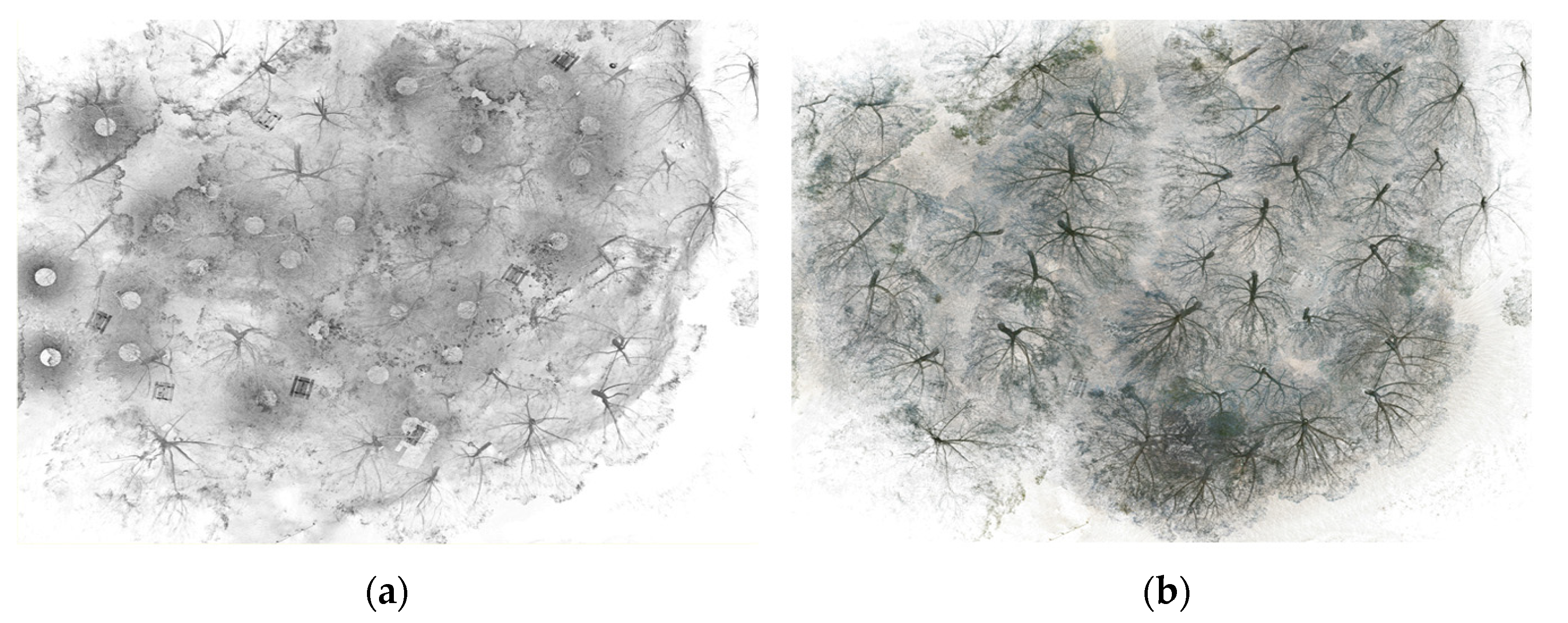
3.1.1. Tree Canopy

For the first analysis, the point clouds were dissected along longitudinal and transversal planes, intersecting each other at the center of the clouds. The visualization was adjusted to the cross-sections of the planes, and the information beyond the planes was retained. The objective was to visually verify the quality of the two clouds in the zones with better data capture (a centralized area of the study object) and with greater canopy coverage. One of the first features that stands out is the more realistic appearance of the BLK2GO cloud, mainly due to the application of color (Figure 5).
The comparison of the point clouds started with the quality of the representation of the canopy. BLK2GO seems to be able to better construct the total crown than Faro Focus 3D. However, a more careful evaluation is needed in this respect, since it is not clear if it is a better representation of the canopies or just a “filling” effect due to the higher level of noise. With a higher transparency of the crowns and in a similar way for the trunks and branches, Faro Focus 3D data seem to be better defined.
We then evaluated the maximum crown height of the trees as captured by the two scanners (Figure 6). To this end, we created three sections along the site with a thickness of 13 m, in the north, in the center, and in the south area, respectively.
We set a common scalar field for the representation of the z-values, and we applied it to the three sections. The three sections reach all the same values in height. The histograms in Figure 6 show that the 99.99% is lower than 13.72m for the entire Faro dataset and 13.97 for the BLK2GO dataset.
Although the two scanners operate with different technologies and have differing degrees of operational limitations related to maximum range, light/shadow conditions, and canopy movement, the results were similar. Both MLS and TLS measured the same crown heights, with maximum points between 11 m and 12 m. The heights of the trees scanned for this research were within the operational range of both scanners.

3.1.2. Terrain and Contour Lines

The Digital Terrain Model (DTM) provides a bare-ground representation of the site terrain. It is a highly useful data set for visualizing surface topography, and it allows for the recognition of main geomorphic features such as slopes, paths, riverbeds, etc. It enables an accurate assessment of the profiles and contours of a site using surveyed field measurements to represent spatial elevation data in a graphical environment.
To be able to work with the topographic data, first we had to separate the points on the ground from the other points in the cloud for each cloud. To do this, the clouds were submitted to the CSF Filter Plugin [26], available in the CloudCompare software. Relief mode was used with Cloth Resolution and Classification Threshold set to 0.1 and Max Iterations set to 500. After segmentation, it was necessary to proceed to a visual inspection and manual cleaning of some remaining points (the bases of tree trunks and the rest of the shrubs close to the ground).
For the presented study, a DTM was created from ground spots extracted among the BLK2GO point cloud entities with the lowest z-values at 20 mm intervals along both the x and y axes; ground points from the Faro point cloud were also decimated on a grid 20 × 20 mm and isolated in a separate cluster for a Cloud-to-Mesh comparison (C2M) (Figure 7a). The DTM presented some bumps in proximity to trees and bushes; some holes on the surface were also visible for the same reason. The C2M analysis aimed to detect the value of the deviation on the DTM from the Faro point cloud, which was used as a reference.
The values of deviation were represented on the DTM surface by a scalar field in an RGB colorscale. The deviation mean was −32 mm. The 69.89% (from yellow to green) of the DTM had a deviation between 0 and +20 mm. In red is shown the area above this value. We also found areas below zero (gray and blue), from −60 mm to 0, as shown in the histogram (Figure 7b).
The highest values of deviation, in absolute distance, could depend on different factors, such as: the accuracy of the BLK2GO was lower than the Faro’s ones, the automatic process for the creation of the DTM generated the error, or the point cloud was not clean enough and some groups of points above (and below) the ground were still present.
From a visual analysis, it resulted that the zones with the highest value of deviation were the ones where bushes and fallen leaves were more present on the ground, and so those parts were less precise.
To verify whether the error came from the conversion of the point cloud into a mesh or from a lack of sensor accuracy operating in this specific environment, we compared the two terrain segmented clouds, still using the Faro as a reference. Despite the fact that the mean error was acceptable for the purpose of a DTM at the scale of representation 1:50 or superior, we wanted to investigate the nature of the absolute error locally. We used the non-decimated point clouds of the terrain, and we performed first a cloud-to-cloud (C2C) comparison by absolute values and then a cloud-to-cloud comparison for topography (M3C2) [28,29], only measuring the z-distances.
Figure 7d shows the results of the M3C2 distance analysis. The deviation values were more clear than the ones obtained from the previous C2M. The white part showed where the error was close to zero; positive (purple) and negative (green) z-distances were balanced. The concentration of negative values was where the slope of the terrain increased, where more leaves were deposited, and at the edges of beaten earth paths. The positive values, alternatively, were more concentrated in the lower areas of the site, where probably the leaves had moved and accumulated from other areas.
A thought on the results of the C2C analysis (Figure 7c) is also necessary. It shows the absolute distances between the two datasets of the terrain, from blue (low) to red (high). The areas where the Faro point cloud had a lack of data are in black, and so the comparison was not possible. The areas in proximity to the black ones, in which the scalar field was generated by interpolation of points contained in a local neighborhood, are also shown in red. So, the high values of error shown on the scalar field of the C2M analysis, near to those where the Faro dataset lacked points, are the result of poor interpolation, and they can be overlooked.
The analysis of the quality of the terrain information was needed to subsequently create contour lines and evaluate the quality of this output. The rasterize tool on CloudCompare was used to construct contour lines from the non-decimated point clouds. A grid of 0.5 was established in the Z direction, with interpolation of empty cells.
The contour lines were then made from the lowest point of each cloud, every 0.50 m. The result, shown in Figure 8, shows similar contour lines, with both TLS and MLS being able to provide a general morphology of the terrain. In some small areas, the two images look slightly different. This is because both clouds still kept the points of the tripods and other working tools used on the ground during the scanning and of the operators that executed the scans. When evaluated in detail, the curves produced by MLS show slightly more “oscillations” than the ones produced automatically from the Faro Focus scanner.
It can be concluded that the contour lines obtained with TLS seem more accurate and reliable; however, MLS has proven to be a good tool for producing terrain profiles with relatively good information in a short time. With a few minutes of scanning and some simple data processing, it was possible to obtain extensive terrain information.

3.1.3. Trunk Diameter at Breast Height

Another important piece of information to be analyzed is the quality of the definition of the trunks’ boundaries in the horizontal cross sections. Laser scanning used for both forest mapping and historical gardens should produce good trunk cross sections at a height of 1.37 m so that the Diameter at Breast Height (DBH) can be established. There are several studies [18,25,27] analyzing this factor. One of the main causes mentioned as hindering trunk measurement was the level of noise in the sections of clouds generated by the MLS. High noise on the trunks’ surface is usually corrected with cleaning filters that decrease the number of points in the cloud.
Thus, automatic detection and measurement of trunks by means of algorithms can be compromised [18]. Comparing the point cloud sections obtained with the two sensors, a difference in the definition level of the points on the trunk perimeters is visible (Figure 9).
Horizontal portions of clouds 10 cm thick and positioned 2 m above the ground were used for this comparison. The trunk sections, produced by BLK2GO and analyzed without previous cleaning procedures, appeared to have a good amount of points. Despite this, the points were scattered around what should be the surface of the trunk, which would hinder both manual and automatic construction of the trunk perimeter.
The sections produced by Faro Focus presented a greater density and uniformity of points and, consequently, a better geometric definition of the trunks. The characteristics observed in these two clouds repeat those already observed in other studies [18,25,27].
Although the MLS point cloud has a higher noise level, it is important to emphasize that MLS is able to detect more trees in a shorter scan time than TLS and, in doing so, is able to determine the complete shape of their trunks (Figure 10). Time is a factor considered important in this analysis. With a scan of about 20 min, the BLK2GO was able to provide a general mapping of the area and completely represent the trees and their trunks. TLS, in a scanning process of about 3.5 h, showed some difficulty in identifying complete sections of trunks and presented data with different levels of detail—detailing areas closest to the scanner positions and gradually reducing the information for more distant areas. Overall, the MLS took a more homogeneous reading and provided a better view of the trees in less time.

3.1.4. Under-Canopy Data Completeness

The detailed structure information under the canopy is important for garden surveying because it ensures that all relevant information about the trees and their environment is captured. This is particularly important for tasks such as measuring tree height, diameter, and volume, as well as for creating detailed 3D models of the trees and the forest canopy. Three-dimensional modeling trees from point clouds can be beneficial for a variety of applications, such as garden management. Researchers and practitioners may use 3D modeling to create detailed models of trees to gain a better understanding of their structure and geometry, as well as to create 3D digital inventories.
3D modeling of trees is now commonly performed using semiautomatic procedures as it can be a repetitive and time-consuming operation; e.g., the RANSAC Shape Detection plugin in CloudCompare is a widely used method for fitting a 3D model to a point cloud [30,31,32,33] in forestry studies. The plugin uses RANSAC, an iterative algorithm, to identify patterns or shapes within the point cloud by selecting a subset of points and fitting a cylinder to those points (trunk and branches).
The ability to effectively generate accurate 3D models of trees relies heavily on the completeness of the point cloud data. Without a complete point cloud, the process of generating a 3D model would be hindered, resulting in an incomplete and inaccurate representation of the tree. In our study, we evaluated the completeness of the two datasets by segmenting both point clouds into 5 cm slices at various heights (1, 2, 3, 4, and 5 m) from the ground. By doing so, we were able to identify any gaps or lack of data in the point cloud. We excluded data above 5 m from the analysis as it tended to be obscured by the dense foliage of branches, which could compromise the statistics (Figure 11).
We first identified the trees whose point clouds were complete at each of their sections (i.e., T7–T12, T14, T18–T20, T22–T26, T29). Then, for each dataset, we calculated the percentage of trunk circumference visible from the point cloud for each section at 1, 2, 3, 4, and 5 m from the ground and reported the values in Table 2.
The results of our analysis indicate that the BLK2GO point cloud of the under-canopy area of the tree exhibited a higher degree of completeness by 10.4% in comparison to the point cloud generated by the Faro sensor.
The point cloud data for certain trees located on the boundary of the site, as identified by a star (*) in Table 2, were found to be incomplete—because we did not scan them entirely. By removing these trees from the count, a more accurate comparison of completeness can be made. The analysis revealed that the BLK2GO sections had an average completeness of 99.6%, while the Faro sections had an average completeness of only 86.2%. This indicates that the BLK2GO point cloud of the under-canopy area of the trees exhibited a higher degree of completeness by 13.4% when compared with the point cloud generated by the Faro sensor.
However, according to the study of Nurunnabi et al. [33], which evaluated different algorithms, including RANSAC, on incomplete point clouds, it was found that both datasets have a sufficient degree of completeness for a successful automatic cylinder-fitting process.

4. Discussion

The main objective of the results presented above is to provide adequate information on the quality of point clouds generated for the creation of databases and graphic documentation used by professionals for garden conservation projects. From this point of view, it is therefore important to give priority to scans that achieve greater precision in terms of measurements and the spatial positioning of trees and furniture elements. Alternatively, when evaluating the range of actions involved in heritage conservation, it is important to consider the use of survey data of historic gardens for the creation of other outputs—mostly visual—such as web platforms and media, which sometimes do not require total precision. Three-dimensional reconstructions and the creation of virtual reality environments, for example, are two ways of using these data where high accuracy is not always required.
Despite the considerable advances in MLS technology in recent years, the TLS still produces information that is more accurate. Even with a lower quantity of points and a significantly smaller file size—also because the scans were not colored—the quality of the points on the surface of the objects obtained with TLS is superior. The MLS point cloud used in this analysis has about 40,000,000 more points than the TLS point cloud, but the cloud shows more noise (Figure 12).
However, MLS was able to produce, in a much shorter time, a similar result that may prove satisfactory for garden documentation. In general, the TLS fieldwork and office work are considerably longer—in relation to the time required to complete the on-site scanning, the amount of equipment that must be loaded and moved during the process, and the additional time required to register the numerous scans acquired.
MLS has been proven to be able, even with a lower degree of precision, to produce similar results to TLS in many of the analyses conducted. The SLAM technology was able to scan a wooded area with fast results despite the uneven terrain and dense foliage. Another factor to emphasize in relation to MLS was its ease of handling on site in slightly rough terrain and its practicality compared with TLS in these same conditions.
Also, we did not test or discuss, in the analysis section, the existing software for the manipulation of data acquired by BLK2GO, namely Cyclone 3DR by Leica Geosystems, that would enable semi-automatic extraction of tree diameters from a point cloud. The work flow consists of a few steps, which are listed below. We marked with the letter “A” the ones that can be run automatically in order to give an idea of the easy process for the information extraction of trunk diameter:
-
Creating a digital terrain model (DTM) from the point cloud (A); shifting the created DTM by a certain Z value to correspond to the level (distance from the ground) on which the trunks will be cut and the trunk diameter will be extracted.
-
Splitting the point cloud to get a point cloud slice with a defined thickness (a suggested value of 0.05 m) on the shifted DTM (A).
-
Isolating the created slice representing the trunk cuts and dividing the point cloud into portions corresponding to each trunk—it is used “split by distance” for this process with a value set at 0.05 m (A). Trunks too close to each other must be separated manually.
-
Running the automatic extraction of “circles,” selecting all the point clouds that correspond to all the trunks (A), and sending directly the “circles” to Autodesk AutoCAD.
This feature available on Cyclone 3DR would save time for the operation related to the extraction of trees’ attributes and also for the DTM automatic extraction.
Despite the fact that Cyclone 3DR would decrease the time for the operations described above, it must be taken into account that the software is not open source and requires the purchase of a license for product activation, which could impact the project budget.
In light of what has been said and the data collected in this research, the choice between TLS and MLS for surveying historic gardens is still hard to make. It falls under the following considerations: it depends on what the site conditions are (site extension, presence of a good level of light, accessibility, etc.), the information to be produced, and, above all, the time available for the survey.
To evaluate more clearly our experience with the two sensors, we listed in Table 3 the main issues we faced during the surveying activities. We assigned to each of the issues an impact factor, from 1 to 5, for both scanners. The complexity of the operations, on site and in the office, increases with a higher value of the impact index, which takes into account costs, time, and health and safety procedures to complete the survey. This table should help in comparing the operational differences between the Faro Focus 3D and the BLK2GO. The list of “issues” is ordered in the real-world sequence they appeared, so the ones connected to site activities came first, and then the ones linked to evaluating raw data characteristics, cloud pre-processing, cloud processing, and data extraction.
The characteristic of gardens and wooded areas in general is the lack of geometric elements on site to be used as references for connecting the scans between them. For this reason, choosing the static scanner Faro Focus 3D implied the indispensable use of fixed targets (in our case, black and with targets and spheres), which dramatically increased data acquisition and registration time and complexity; that is why issues n. 1, 3, 6, 8, and 14 got a high impact score.
The BLK2GO did not need any targets, but it received a 3 impact score for issue n. 6 because there was a risk that the scanner would lose its “initialization” during our experiment and consequently require the help of ground references for correctly completing the data acquisition. The quality and validity of the scans produced by the BLK2GO depend on the SLAM technology and the VIS process, both of which work in remote connection with the scanner base station. SLAM uses resection and forward intersection for the navigation between captures and the detection of geometric features in the field. The accuracy of the scans can be invalidated if the site does not have good geometric features that can be identified and captured by the scanner, or if the site characteristics do not permit the transmission of the stored data to the base station. The use of ground control points would increase control over the site’s operation and the accuracy of the scans. This process is suggested for larger sites than the one studied for this research.
Regarding issue n. 2, which can also be a reference in the decision of which sensor to use, it is important to underline that the BLK2GO operating range is limited to a 25 m distance, which forecloses the usage of the scanner for some sites, such as in urban areas where buildings reach heights of more than eight floors. We measured oak trees about 13 m tall in our experiment, and the scanner offered a complete point cloud up to the treetops. However, in some historic gardens where hundred-year-old trees can be found, they can exceed 25 m in height.
Additionally, issue n. 9 shows that the BLK2GO cannot be used in places with a lack of light or at night since it works with integrated cameras that need a sufficient level of brightness to operate.
Issue n. 10 has a greater impact on the operation of BLK2GO because one battery only lasts 40 min. We saw that in 20 min of scanning with the BLK2GO, we acquired more data than with the Faro Focus. The scanner is equipped with two batteries by default. So, it is important to manage this issue in advance by finding the facilities where to charge the batteries during site activities.
Since the most important issue, 2 and 3, related to the presented MLS is the impossibility of working in environments with a low level of light and/or for an operating range superior to 25 m, it is relevant for forthcoming studies to mention that other MLS sensors are available on the market, and they can work in complete darkness and at larger distances since they use LiDAR technology—e.g., Zeb Horizon up to 100, Leica Pegasus up to 200 m.
From an analytic point of view, since the mean impact value reported in Table 3 is lower for the BLK2GO, we can say that, over all, the choice of this sensor was more convenient than the Faro Focus 3D.

5. Conclusions

The research presented in this paper compares the data captured with mobile laser scanning (MLS) and terrestrial laser scanning (TLS) of the same forested area and analyzes the efficiency of each method. The evaluations were restricted to visual observation, measurements, and C2C/C2M/M3C2 comparisons. In general, MLS is able to survey a larger area in less time and with greater ease on the field than TLS. TLS, however, is still the method that produces more accurate results with a higher density of points on the surfaces of the objects present in the scanned area, which implies a better definition of the elements present in the site.
Regarding the survey of historic gardens, the research concludes that the type of laser scanning to be used depends on the conditions available for the survey, its objective, and the type of material one wants to produce. Both TLS and MLS present qualities to be exploited in the production of graphic documentation to support the preservation actions of green areas. The study also reinforces that MLS, when used following control parameters at the time of scanning, can be an important and efficient support to streamline the preservation actions of historic gardens by producing quality point clouds in reduced time and with greater ease in field work.
However, there is a particularity of historic gardens compared with other monuments or built heritage that can function as a determining factor in the choice between TLS and MLS, and this factor is directly related to time. Most of the compositional elements of historic gardens are of a plant nature; therefore, they are alive, dynamic, perishable, and renewable. These elements are subject to changes in time, natural cycles, and climatic conditions. The practicality of MLS data acquisition, together with the relative accuracy and quality of the information obtained, makes it possible, for example, to periodically scan a garden for plant growth according to the landscape architect’s design. Furthermore, by doing so, the state of evolution of the garden is documented, as required by the 1981 ICOMOS-IFLA “Florence Charter” [5].
Gardens often change shape, for example, with the passing of the seasons, and MLS can be a tool that allows the frequent documentation of such changes. In general, MLS is able to represent the total scanned area more comprehensively and in less time than TLS. In just a few minutes, it is possible to reconstruct the garden spaces in a virtual environment and obtain important information from them.

Author Contributions

Conceptualization G.D.D.; Data curation C.M., G.D.D.; Formal analysis G.D.D.; Funding acquisition G.D.D.; Investigation G.D.D., C.M.; Methodology G.D.D.; Project Administration G.D.D.; Resources G.D.D.; Software G.D.D., C.M.; Supervision G.D.D.; Validation G.D.D.; Visualization G.D.D.; Writing—original draft G.D.D., C.M.; Writing—review & editing G.D.D. All authors have read and agreed to the published version of the manuscript.

Funding

This research was funded by the European Union’s Horizon 2020 Research and Innovation Programme under the Marie Skłodowska-Curie grant agreement No 895320. Researcher: Graziella Del Duca.

Institutional Review Board Statement

Not applicable.

Informed Consent Statement

Not applicable.

Data Availability Statement

Not applicable.

Acknowledgments

The authors would like to thank Leica Geosystems Portugal for their support during the forestry survey carried out with the BLK2GO.

Conflicts of Interest

The authors declare no conflict of interest.

References

  1. Machat, C.; Ziesemer, J. Heritage at Risk. World Report 2016–2019 on Monuments and Sites in Danger. Hendrik BÄßLER Verlag. 2020. Available online: https://www.icomos.de/icomos/pdf/hr20_2016_2019.pdf (accessed on 21 December 2022).
  2. World Meteorological Organization. WMO Atlas of Mortality and Economic Losses from Weather, Climate and Water Extremes (1970–2019); World Meteorological Organization: Geneva, Switzerland, 2021; ISBN 978-92-63-11267-5. Available online: https://library.wmo.int/doc_num.php?explnum_id=10989 (accessed on 21 December 2022).
  3. Mitchell, N.; Rössler, M.; Tricaud, P.M. World Heritage Cultural Landscapes: A Handbook for Conservation and Management; World Heritage Series: 26; UNESCO: Paris, France, 2009; Available online: https://unesdoc.unesco.org/ark:/48223/pf0000187044 (accessed on 21 December 2022).
  4. UNESCO/ICCROM/ICOMOS/IUCN. Managing Disaster Risks for World Heritage; World Heritage Resource Manual Series; United Nations Educational, Scientific and Cultural Organization: Paris, France, 2010; ISBN 978-92-3-104165-5. Available online: https://whc.unesco.org/en/managing-disaster-risks/ (accessed on 21 December 2022).
  5. ICOMOS. The Florence Charter. 1982. Available online: https://www.icomos.org/en/179-articles-en-francais/ressources/charters-and-standards/158-the-florence-charter (accessed on 21 December 2022).
  6. Clark, N.A.; Wynne, R.H.; Schmoldt, D.L.; Winn, M. An assessment of the utility of a non-metric digital camera for measuring standing trees. Comput. Electron. Agric. 2000, 28, 151–169. Available online: https://www.srs.fs.usda.gov/pubs/VT_Publications/00t3.pdf (accessed on 21 December 2022). [CrossRef] [Green Version]
  7. Hyyppä, E.; Yu, X.; Kaartinen, H.; Hakala, T.; Kukko, A.; Vastaranta, M.; Hyyppä, J. Comparison of Backpack, Handheld, Under-Canopy UAV, and Above-Canopy UAV Laser Scanning for Field Reference Data Collection in Boreal Forests. Remote Sens. 2020, 12, 3327. [Google Scholar] [CrossRef]
  8. Taketomi, T.; Uchiyama, H.; Ikeda, S. Visual SLAM algorithms: A survey from 2010 to 2016. IPSJ Trans. Comput. Vis. Appl. 2017, 9, 16. [Google Scholar] [CrossRef] [Green Version]
  9. Tucci, G.; Visintini, D.; Bonora, V.; Parisi, E.I. Examination of Indoor Mobile Mapping Systems in a Diversified Internal/External Test Field. Appl. Sci. 2018, 8, 401. [Google Scholar] [CrossRef] [Green Version]
  10. La Russa, F.M.; Galizia, M.; Santagati, C. Remote sensing and city information modeling for revealing the complexity of historical centers. Int. Arch. Photogramm. Remote Sens. Spat. Inf. Sci. 2021, XLVI-M-1-2021, 367–374. [Google Scholar] [CrossRef]
  11. Sammartano, G.; Spanò, A. Point clouds by SLAM-based mobile mapping systems: Accuracy and geometric content validation in multisensor survey and stand-alone acquisition. Appl. Geomat. 2018, 10, 317–339. [Google Scholar] [CrossRef]
  12. Marques Freguete, L.; Chu, T.; Starek, M. Mapping with LIDAR and structure-from-motion photogrammetry: Accuracy assessment of point cloud over multiple platforms. In Proceedings of the Remote Sensing Technologies and Applications in Urban Environments VI, SPIE Remote Sensing, Online, 13–18 September 2021; SPIE: Bellingham, WA, USA, 2021; p. 11. [Google Scholar] [CrossRef]
  13. Sammartano, G.; Previtali, M.; Banfi, F. Parametric generation in HBIM workflows for slam-based data: Discussing expectations on suitability and accuracy. In Proceedings of the Joint International Event 9th ARQUEOLÓGICA 2.0 & 3rd GEORES, Valencia, Spain, 26–28 April 2021; Editorial Universitat Politècnica de València: Valencia, Spain, 2021; pp. 374–388. [Google Scholar] [CrossRef]
  14. Wang, C.-C.; Thorpe, C.; Thrun, S.; Hebert, M.; Durrant-Whyte, H. Simultaneous Localization, Mapping and Moving Object Tracking. Int. J. Robot. Res. 2007, 26, 889–916. [Google Scholar] [CrossRef]
  15. Bahraini, M.S.; Rad, A.B.; Bozorg, M. SLAM in Dynamic Environments: A Deep Learning Approach for Moving Object Tracking Using ML-RANSAC Algorithm. Sensors 2019, 19, 3699. [Google Scholar] [CrossRef]
  16. Kumazaki, R.; Kunii, Y. Drawing and landscape simulation for japanese garden by using terrestrial laser scanner. Int. Arch. Photogramm. Remote Sens. Spat. Inf. Sci.—ISPRS Arch. 2015, 40, 233–238. [Google Scholar] [CrossRef] [Green Version]
  17. Hess, M.; Ferreyra, C. Recording and comparing historic garden architecture. value of slam-based recording for research on cultural landscapes in connection with heritage conservation. Int. Arch. Photogramm. Remote Sens. Spat. Inf. Sci.—ISPRS Arch. 2021, 46, 301–308. [Google Scholar] [CrossRef]
  18. Pérez-Martín, E.; Medina, S.L.C.; Herrero-Tejedor, T.; Pérez-Souza, M.A.; de Mata, J.A.; Ezquerra-Canalejo, A. Assessment of tree diameter estimation methods from mobile laser scanning in a historic garden. Forests 2021, 12, 1013. [Google Scholar] [CrossRef]
  19. Herrero-Tejedor, T.R.; Arqués Soler, F.; Medina, S.L.C.; de La O’Cabrera, M.R.; Romero, J.L.M. Documenting a cultural landscape using point-cloud 3d models obtained with geomatic integration techniques. The case of the El Encín atomic garden, Madrid (Spain). PLoS ONE 2020, 15, e0235169. [Google Scholar] [CrossRef] [PubMed]
  20. Jia, S.; Liao, Y.; Xiao, Y.; Zhang, B.; Meng, X.; Qin, K. Methods of Conserving and Managing Cultural Heritage in Classical Chinese Royal Gardens Based on 3D Digitalization. Sustainability 2022, 14, 4108. [Google Scholar] [CrossRef]
  21. Liang, H.; Li, W.; Lai, S.; Zhu, L.; Jiang, W.; Zhang, Q. The integration of terrestrial laser scanning and terrestrial and unmanned aerial vehicle digital photogrammetry for the documentation of Chinese classical gardens—A case study of Huanxiu Shanzhuang, Suzhou, China. J. Cult. Herit. 2018, 33, 222–230. [Google Scholar] [CrossRef]
  22. Dlesk, A.; Vach, K.; Šedina, J.; Pavelka, K. Comparison of leica blk360 and leica blk2go on chosen test objects. Int. Arch. Photogramm. Remote Sens. Spat. Inf. Sci. 2022, XLVI-5/W1-2022, 77–82. [Google Scholar] [CrossRef]
  23. Limongiello, M.; Ronchi, D.; Albano, V. BLK2GO for DTM generation in highly vegetated area for detecting and documenting archaeological earthwork anomalies. In Proceedings of the 2020 IMEKO TC-4 International Conference on Metrology for Archaeology and Cultural Heritage, Virtual Conference, 22–24 October 2020; pp. 316–321. [Google Scholar]
  24. Piniotis, G.; Soile, S.; Bourexis, F.; Tsakiri, M.; Ioannidis, C. Experimental assessment of 3d narrow space mapping technologies. Int. Arch. Photogramm. Remote Sens. Spat. Inf. Sci.—ISPRS Arch. 2020, 43, 149–156. [Google Scholar] [CrossRef]
  25. Gollob, C.; Ritter, T.; Nothdurft, A. Forest inventory with long range and high-speed Personal Laser Scanning (PLS) and Simultaneous Localization and Mapping (SLAM) technology. Remote Sens. 2020, 12, 1509. [Google Scholar] [CrossRef]
  26. Zhang, W.; Qi, J.; Wan, P.; Wang, H.; Xie, D.; Wang, X.; Yan, G. An easy-to-use airborne LiDAR data filtering method based on cloth simulation. Remote Sens. 2016, 8, 501. [Google Scholar] [CrossRef]
  27. Lague, D.; Brodu, N.; Leroux, J. Accurate 3D comparison of complex topography with terrestrial laser scanner: Application to thr Rangitikei canyon (N-Z). ISPRS J. Photogramm. Remote Sens. 2013, 82, 10–26. [Google Scholar] [CrossRef] [Green Version]
  28. James, M.R.; Robson, S.; Smith, M.W. 3-D uncertainty-based topographic change detection with structure-from-motion photogrammetry: Precision maps for ground control and directly georeferenced surveys. Earth Surf. Process. Landf. 2017, 42, 1769–1788. [Google Scholar] [CrossRef]
  29. Maté-González, M.Á.; Di Pietra, V.; Piras, M. Evaluation of Different LiDAR Technologies for the Documentation of Forgotten Cultural Heritage under Forest Environments. Sensors 2022, 22, 6314. [Google Scholar] [CrossRef]
  30. Proudman, A.; Ramezani, M.; Digumarti, S.T.; Chebrolu, N.; Fallon, M. Towards real-time forest inventory using handheld LiDAR. Robot. Auton. Syst. 2022, 157, 104240. [Google Scholar] [CrossRef]
  31. Friedrich, M.; Illium, S.; Fayolle, P.-A.; Linnhoff-Popien, C. CSG Tree Extraction from 3D Point Clouds and Meshes Using a Hybrid Approach. Commun. Comput. Inf. Sci. 2022, 1474, 53–79. [Google Scholar]
  32. Polat, N.; Uysal, M. An investigation of tree extraction from UAV-based photogrammetric dense point cloud. Arab. J. Geosci. 2020, 13, 846. [Google Scholar] [CrossRef]
  33. Nurunnabi, A.; Sadahirob, Y.; Lindenbergh, R. Robust cylinder fitting three-dimensional point cloud data. Int. Arch. Photogramm. Remote Sens. Spat. Inf. Sci. 2017, XLII-1/W1, 63–70. [Google Scholar] [CrossRef]
Figure 1. Site localization in red. The studied area is located in Monsanto Park, near the Faculty of Architecture in Lisbon.
Heritage 06 00057 g001
Figure 2. Top view of the surveyed areas with TLS (a) and MLS (b).
Heritage 06 00057 g002
Figure 3. Point clouds of the scope area obtained with the TLS (a) and MLS (b). Difference in density, detail accuracy, and level of noise is already noticeable from this top view.
Heritage 06 00057 g003
Figure 4. Comparison between the two point clouds. (a) The two point clouds are overlayed in a horizontal slice having a height of 10 cm: in red, that of Faro Focus, and in green, that of BLK2GO. (b) Histogram of C2C comparison. (c) C2C analysis.
Heritage 06 00057 g004
Figure 5. Point clouds of the scope area obtained with the TLS (a) and MLS (b), respectively.
Heritage 06 00057 g005
Figure 6. Maximum crown height of the trees. Tree crown profile is complete in both MLS (a) and TLS (b) scans. Sections S1, S2, and S3 display point clouds as captured by the two scanners and they are visualized by z-scalar field. Section box extensions in (c). Point distribution diagrams in (d,e); the highest point for Faro dataset is at 13.73 m, and it is at 13.94 m for BLK2GO dataset.
Heritage 06 00057 g006
Figure 7. Terrain data comparison. (a) Cloud-to-mesh comparison between the reference data (Faro Focus point cloud) and the Digital Terrain Model generated from the segmented terrain cloud acquired with the Leica BLK2GO scanner. (b) Histogram describing the deviation distribution. (c) Cloud-to-cloud comparison; Faro Focus 3D point cloud is set as reference data. (d) M3C2 cloud-to-cloud Z-distance analysis.
Heritage 06 00057 g007
Figure 8. Contour lines every 50 cm are obtained from the Faro Focus’s point cloud (a) and BLK2GO’s (b).
Heritage 06 00057 g008
Figure 9. Horizontal sections of trunks obtained at a height of 2 m from the ground.
Heritage 06 00057 g009
Figure 10. Horizontal sections of the trees on the periphery area obtained by TLS and MLS. Although there is more noise, MLS is able to better define the sections in less scanning time.
Heritage 06 00057 g010
Figure 11. 5cm tick point cloud slices, respectively, at 1 m (blue), 2 m (dark green), 3 m (light green), 4 m (yellow), and 5 m (red) height from the terrain. (a) 3D visualization of the sections. (b) Two-dimensional plan view of the trunk sections; those included in the perimeter area are the sections where the point cloud describes the entire trunk perimeter at each level, for both Faro and BLK2GO data.
Heritage 06 00057 g011
Figure 12. Perspective view of the total surveyed area: TLS (a) and MLS (b).
Heritage 06 00057 g012
Table 1. Main performance indicators of Faro Focus S 120 and Leica BLK2GO.
IndicatorsFaro 3D DescriptionsBLK2GO Descriptions
SystemPhase-shift basedGRANDSLAM-based
3D Position Accuracy±2 mm at 10 m and 90% reflectivity; 25 m at 10 m and 10% reflectivity±10 mm indoors
Range Noise0.6 mm at 10 m and 10% refl.;
0.3 mm at 10 m and 90% refl.
±3 mm
Operating Range0.6–120 m0.5–25 m
Field-of-View360° (horizontal); 300° (vertical)360° (horizontal); 270° (vertical)
Point measurement rateup to 976,000 points/sec420,000 pts/sec
Wavelength905 nm830 nm
Color UnitUp to 70 megapixels in colorHigh resolution camera:12 Mpixel, 90° × 120°, rolling shutter
Operating temperature+5 to +40 °C0 to +40 °C
Weight5 kg (including battery)775 g (including battery)
Sensors’ specs in Table 1 are extracted from: https://knowledge.faro.com/@api/deki/pages/14794/pdf/Performance%2bSpecifications%2bfor%2bthe%2bFocus3D.pdf?stylesheet=default (updated on Thu, 12 Jan 2023 15:26:04 GMT; accessed on 21 January 2023). https://shop.leica-geosystems.com/leica-blk/blk2go/product-details (accessed on 21 January 2023).
Table 2. Point cloud completeness on trunk surfaces.
Slice Height from Terrain1 m2 m3 m4 m5 m
Sensor TypeTLSMLSTLSMLSTLSMLSTLSMLSTLSMLS
T183%100%84%100%85%100%75%97%87%95%
T2 *68%100%75%100%75%100%79%100%77%100%
T359%100%61%100%71%100%65%100%74%100%
T4 *61%55%63%53%61%52%55%53%-51%
T585%100%85%100%85%100%81%100%81%100%
T693%100%93%100%91%100%84%100%78%100%
T7–T12, T14, T18–T20100%100%100%100%100%100%100%100%100%100%
T22–T26, T29100%100%100%100%100%100%100%100%100%100%
T11100%100%88%100%73%100%100%100%100%100%
T13 *68%92%67%93%62%92%61%93%56%91%
T1586%100%91%100%78%100%72%100%83%100%
T16 *64%76%66%63%72%60%30%65%63%50%
T17100%100%100%100%91%100%91%100%100%100%
T21100%100%100%100%92%100%91%100%100%100%
T2787%100%100%100%100%100%88%100%80%100%
T2878%100%73%100%73%100%64%100%-100%
T30100%100%100%100%100%100%97%100%95%100%
T3190%100%93%100%100%100%100%100%100%100%
T32 *70%80%69%100%67%100%67%100%65%53%
T33 *79%100%63%100%63%100%64%100%62%100%
T3465%100%63%100%66%100%65%100%67%100%
T35 *66%100%72%100%73%100%57%100%64%100%
T36 *85%100%83%100%82%100%83%100%83%100%
Total average82%95%82%96%80%95%77%69%75%93%
Average excluding trees
marked by (*)
88%100%89%100%87%100%84%99%83%99%
Table 3. Impact of the two scanners on land surveying work. We identified and listed 18 issues related to the laser scanning and surveying of historic gardens. The impact index, with a value from 1 to 5, represents the level of complexity of the operations, costs, time, and health and safety procedures to take into account to complete the survey.
Issue N.Issue DescriptionImpact Score if Used
Faro Focus 3D
from 1 to 5 [1 Low, 5 High]
Impact Score if Used
BLK2GO
from 1 to 5 [1 Low, 5 High]
1Operators and equipment needed for site activities51
2Sensor operating range15
3Lack of geometric references on site55
4Site reduced visibility (due to plants and other obstacles) 41
5Site access (uneven or steep terrain, caves, etc.)31
6Unstable ground surface (wet terrain)51
7Use of targets, spheres, or ground control points53
8Scans time set up51
9Scanning time52
10Light dependency15
11Colored scans41
12Scanner battery consumption25
13Scans with color51
14File size13
15Point cloud noise 13
16Scans, cleaning, and filtering34
17Registration complexity51
18Tree attribute extraction and DTM creation52
Total
Average
65
3.6
45
2.5
Disclaimer/Publisher’s Note: The statements, opinions and data contained in all publications are solely those of the individual author(s) and contributor(s) and not of MDPI and/or the editor(s). MDPI and/or the editor(s) disclaim responsibility for any injury to people or property resulting from any ideas, methods, instructions or products referred to in the content.

