Abstract
In this paper, a composite control strategy for improved off-grid configuration based on photovoltaic (PV array), a wind turbine (WT), and a diesel engine (DE) generator to achieve high performance while supplying nonlinear loads is investigated. To operate the WT efficiently under variable speed conditions and to obtain accurate and fast convergence to the maximum global operating point without a speed sensor, an iterative interpolation method is integrated with the perturbation and observation (P&O) technique. To ensure the balance of power in the system and to achieve the maximum power from the PV array without using any maximum power point tracking (MPPT) method, and ensuring stable operation during the disturbance, a double-loop control strategy for a two-switches buck-boost converter is developed. Furthermore, to protect the synchronous generator of the diesel generator (DG) from the 5th and 7th order-harmonics created by the connected nonlinear loads and to solve the issue of the filter resonance, the interfacing three-phase inverter is controlled using an improved synchronous-reference frame algorithm (SRF) with virtual impedance active damping. The presented work demonstrates effective and efficient control along with improved performance and cost-effective option as compared to the similar works reported in the literature. The performance of the presented off-grid configuration and its developed composite control strategy are tested using MATLAB/Simulink and validated through small-scale hardware prototyping.
1. Introduction
The hybrid off-grid power generation system based on renewable energy sources (RES), such as a wind turbine (WT), photovoltaics (PVs array) a non-renewable diesel generator (DG), and an energy storage system (ESS), has demonstrated its capability to provide uninterrupted and clean energy to the connected electrical local loads at low cost [1,2,3]. Many off-grid configurations based on the hybridization of different RESs, and their control strategies, are detailed in [4,5]. In all these off-grid configurations, non-renewable energy sources (N-RESs) are suggested as reliable energy sources to compensate for the intermittency of RES and always ensure uninterruptible power supply to the connected local loads. Detailed comparisons on off-grid configurations, control design, and application are given in [6,7,8]. DG, which consists of a diesel engine (DE) and electrical machine in a hybrid off-grid system, is employed as backup ES and is connected directly to the point of common coupling (PCC) to fulfill the connected linear and nonlinear loads, as detailed in all off-grid configurations presented in [9]. According to the detailed study, realized by [9] on the induction machine, the harmonics generated by nonlinear loads can affect the performance of the electrical and mechanical parts of the DG, and in [10], the authors have found that 5th and 7th harmonics have a significant impact on the performance of the synchronous machine. To prevent this issue and to improve the operational effectiveness of DG, in [10], the 5th and 7th harmonics are eliminated by controlling the interfacing inverter as a shunt active filter using multifunction control algorithm based on PRC controllers, while showing satisfactory performance under all types of loads. In the same context, the authors in [11] have suggested a passive harmonic filter to mitigate selective harmonics. Compared to an active power filter (APF), the passive power filter (PPF) is less complex and easy to design, but the active filter possesses a high value of the quality factor, which is suggested for applications where many energy sources are connected to the PCC, as in this case. Many research works are reported in the literature on the control and design of the APF [12,13,14]. Unfortunately, all the concepts given in [12,13,14] are dedicated to APF application, which has only one task in a hybrid off-grid application. So, the multitask option is preferred as detailed in [10], where frequency and voltage regulation at the PCC are taken into consideration. In [15,16,17], the synchronous reference frame technique (SRF) is proposed for standalone and grid-connected systems. The obtained results under the presence of nonlinear loads show satisfactory performance. Unfortunately, the performance of this technique for under-voltage and frequency variation has not been presented. In [18], sliding mode control (SMC) is suggested to maintain constant PCC voltage and frequency, and to improve the power quality, simultaneously. The authors have succeeded to validate the proposed control for the off-grid system in real-time, and the obtained results show satisfactory performance. Compared to the SRF technique proposed in [15,16,17], or the instantaneous power theory, SMC is complex and requires an accurate technique to select the optimal SM gains (β1 and β2) to achieve high performance.
The second non-renewable energy source (N-RES) is the energy storage system (ESS), which is considered as the key to the stable operation of the off-grid system, especially if it contains RESs. Generally, the ESS is connected to the common DC bus through a buck-boost converter [18,19] and is controlled to balance the power in the system and compensate for the wind and solar power intermittency and variability. In [20], SMC for DC voltage and battery current regulation is proposed, and in [21], a control scheme based on the state of charge of the battery (SoC%) is employed to charge and discharge lithium-ion battery through a three-phase DC-AC converter. For both studies detailed in [20,21], the authors have succeeded to implement their control strategies in real-time, and the obtained results show the capability of the ESS to maintain the stable operation of the hybrid off-grid system. Unlike the SMC suggested in [20], the strategy based on the SoC%, which is suggested in [21], is simple and performs well under sudden variations of solar irradiation and load change.
With regard to the RES integration in off-grid systems and their output power optimization, authors in [4,5] have proposed a hybrid AC/DC configuration. For output power optimization, perturbation and observation (P&O) technique is widely employed for WT as well as PV array due to its simplicity [22]. According to [23], the P&O technique cannot perform well under a sudden change in solar irradiation or under partial shading. To improve their performance, in [24], P&O is reinforced by the adaptive algorithm to adjust the reference step size, and in [25], the resistance P&O is combined with adaptive resistance control to achieve high performance from the PV panel under sudden solar irradiation change. In [24,25], the objectives are achieved but the system complexity is increased compared to the conventional P&O technique.
For improvement in the performance of the off-grid configurations available and reported in [26,27,28], the following solutions are presented in this paper as significant contributions,
- Minimizing the number of power converters to reduce the hardware complexity and increase the system efficiency,
- Development of an indirect control for the buck-boost converter to realize many tasks such as achieving high performance from PV without using any MPPT algorithm, facilitating the bidirectional power flow between the ESS and PCC, and ensuring stable operation during the disturbance,
- Effective and efficient, mechanical-speed sensorless operation of variable-speed WT-based permanent magnet brushless DC generator (PMBLDCG) using hybridization of the root-finding algorithm (secant method) with P&O technique,
- Reinforcement of the SRF based control with virtual impedance active damping to improve the power quality at the PCC while eliminating the 5th and 7th order harmonics, along with the prevention of the 6th order-harmonic generation in the rotor of the synchronous generator (SG), as well as to solve the issue of filter resonance.
2. System Configuration and Operation
Figure 1 demonstrates an improved version of the off-grid configurations proposed in [26,27,28]. It consists of WT-driven variable speed PMBLDCG, PV, ESS, and DE-driven fixed speed synchronous generator (SG). To achieve high performance from WT without using any mechanical speed sensor, the stator terminals of the PMBLDCG are connected to the common DC bus through a three-phase diode bridge and DC-DC boost converter, which is controlled using the root-finding algorithm (secant method) with the P&O technique. To achieve high performance from PV without losses in power converter, their terminals are connected directly to the common DC bus. The ESS is connected to the common DC bus through a DC-DC buck-boost converter, which is controlled using indirect method-based control to achieve many tasks simultaneously. The WT, PV, and ESS are connected to the PCC through a three-phase interfacing inverter, which is interfaced with an LCL passive filter. To protect the DG, which consists of DE-driven fixed speed SG against the 5th and 7th order harmonics and prevent the generation of the 6th order-harmonic in the rotor of the SG, and avoid the filter resonance, SRF control with virtual impedance active damping is employed.
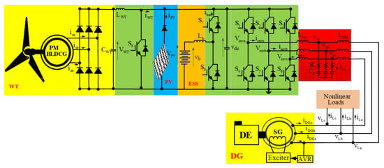
Figure 1.
Improved hybrid wind-PV off-grid configuration under study.
The operation modes of the off-grid system are decided by generated and consumed powers as presented in Table 1. There are four operating modes with specific conditions, such as the state of charge of the battery (SoC%), the generated power from ESs, and the load power demand for the decision of the operating mode. In this study, the operating modes are decided based on the sum of the generated power from WT (PWT), PV (PPV), and DG (PDG), depending on if it is greater, equal, or less than load power demand (PL), and also based on the SoC% of ESS.

Table 1.
Operation modes of the system.
3. Developed Composite Control Strategy
In this section, the developed control strategies for MPPT of the WT and PV panel, charging and discharging the ESS, and energy management, as well as power quality improvement at the PCC, are detailed.
3.1. Control of DC-DC Boost Converter on WT Side
Figure 2 shows the developed enhanced control strategy to achieve MPPT from WT without using a mechanical speed sensor. P&O algorithm, which is detailed in [29], is combined with an iterative interpolation method called secant method with variable step for VWT to provide accurate and fast convergence to the optimum operating point during sudden wind speed change. The fundamental equation of the secant method is described in [30,31,32,33].
where the initial value of and represents the value of the function at , which is described as,
where and represent the output DC voltage and the generated power of WT.
where is the gradient of (n).
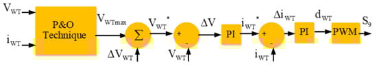
Figure 2.
P&O-based secant method and variable step for DC-DC-boost converter.
From (2) and (3), the step of variation () is obtained as,
The reference voltage is obtained as,
where is the maximum voltage obtained using the P&O technique as detailed in Figure 2.
The reference is compared with sensed DC voltage at the output of the three-phase diode bridge. The error of voltage is fed to the PI voltage controller. The obtained signal from the outer loop control represents the DC WT current reference () as
where and represent the proportional and integral gains of the outer control loop, and is the WT DC voltage error value.
The DC WT current reference is compared with the measured DC WT current (), and the current error () is fed to PI current controller to get control signal () as
where and represent the proportional and integral gains of the inner control loop, and is the WT-DC error value.
This output signal of the PI controller is fed to the PWM controller to get the switching control of the switch (S9) of the boost converter for the WT side.
3.2. Control of DC-DC Buck-Boost Converter for ESS Side
Figure 3 shows the block diagram of the developed indirect control of the DC-DC buck-boost converter. Based on the control of the DC voltage of the common DC bus, one can easily get the maximum power from the PV panel without using any MPPT technique and controlled power converter by connecting many PVs in series to make the output PV panels voltage equal to the common DC bus voltage. So, by controlling the common DC bus voltage (, one balances the power in the hybrid off-grid system and indirectly gets the MPP from the PV array. As shown in Figure 3, two control loops are employed to control the DC-DC buck-boost converter for the ESS side. The error of the common DC bus voltage () is calculated as
where and represent the common reference DC bus voltage and its measured signal.
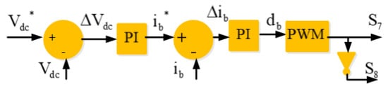
Figure 3.
Indirect control for the DC-DC buck-boost converter for the ESS side.
The obtained error value of the common DC bus voltage () is fed to the PI voltage controller to get the ESS current reference () as
where and represent the proportional and integral gains of the outer control loop, and is the error value of the common DC bus voltage.
The DC-WT current reference is compared with the measured value (), and the current error value () is fed to PI current controller of the inner control loop to get control signal () as
where and represent the proportional and integral gains of the inner control loop.
The output signal of the PI controller of the inner control loop is fed to the PWM controller to get the switching control of switches (S7 and S8) of the DC-DC buck-boost converter for the ESS side.
3.3. SRF Control with Virtual Impedance-Based Active Damping
Figure 4 shows the block diagram of synchronous reference frame (SRF) control based on virtual impedance active damping. The theory of SRF control as detailed in [14] is reinforced by virtual impedance-based active damping to dampen the LCL resonance. The measured load currents () and PCC voltages () are converted into the d-q-o frame using Park’s transformation as,
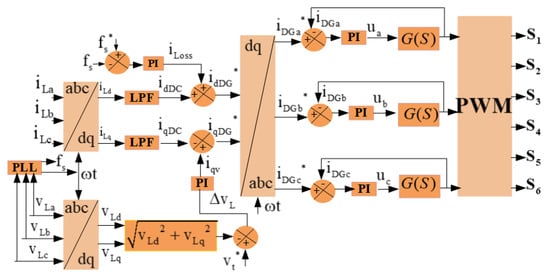
Figure 4.
SRF control with virtual impedance-based active damping.
And
where is the phase angle and is estimated using the phase locked loop (PLL).
With help of a low pass filter (LPF), the DC components () of load current are extracted. The zero sequence is taken equal to zero.
The d-axis reference DG currents () is estimated as
where represents the active power component to maintain the system frequency () constant, and it compensates for the losses in the three-phase interfacing inverter. This active component is estimated as
where is the system frequency reference and is equal to 60 Hz, is the measured system frequency using PLL, and and represent the proportional and integral gains.
The q-axis reference DG currents (), is estimated as
where, is the reactive power component for maintaining the PCC voltage and is calculated as
where and represent the proportional and integral gains, and () is calculated as
where is the reference amplitude voltage at the PCC, and is the measured amplitude of the PCC voltage and is calculated as
where denote the d-q voltage of the PCC and are obtained using (12).
The reference DG currents () are obtained using the reverse Park’s transformation as
The zero sequence is taken equal to zero.
As detailed in Figure 4, the SRF control is reinforced by virtual impedance damping to solve the problem of filter resonance. Then, the equivalent transfer function of the LCL filter with dual feedback active damping is detailed in [34,35] as
where denote the damping coefficients, and and are the inductors and capacitors of the LCL filter.
The reference DG currents () with respective DG currents () are fed to a PWM current controller to get the switching sequences for control of the switches (S1 to S6) of the interfacing inverter.
4. Results and Discussion
To validate the effectiveness and robustness of the hybrid off-grid configuration and its composite control strategies, simulation and experimental tests are presented; they were obtained using Matlab/Simulink and hardware prototype of a 2-kW rating. Figure 5 shows the hardware prototype used for real-time validation of the complete off-grid system shown in Figure 1. It consists of (1) ABB Drive, (2) induction motor, (3) SG, (4) synchronizer, (5) transformer, (6) power converters, (7) voltage and current sensors, (8) loads, (9) protection cards, (10) dSPACE, (11) lead-acid battery pack, (12) PV emulator, (13) drive + induction motor, and (14) PMBLDCG, and (15) LCL filter.
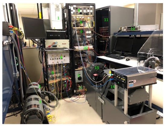
Figure 5.
Hardware prototype of hybrid wind-PV-diesel off-grid system.
4.1. Performance at the AC Side under Presence of Linear Load
Figure 6a shows the waveforms of the stator DG voltages () and currents (), load voltages (), and currents (), and Figure 6b shows the zoom of the waveforms shown in Figure 6a between t = 1.1 s and t = 1.3 s. In this test, a linear load is connected at the PCC. One observes in Figure 6a,b that the stator voltages of the SG are well regulated and are equal to the reference 208 V. The voltage and current at the PCC are constant and sinusoidal. The system frequency is well regulated and is equal to 60 Hz.
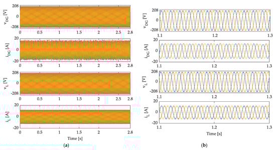
Figure 6.
Performance under fixed linear load at the AC side and (b) Zoom of (a) between t = 1.1 s to 1.3 s.
4.2. Performance at the DC Side at Solar Irradiation and Wind Speed Change
In Figure 7, the waveforms of the common DC-link voltage () and its reference (); ESS current () and its reference ; the state of charge of the ESS (SoC%); the output PV current (); the stator voltage of the phase ‘a’ of the PMBLDCG () and the current (); and the DC-WT current (), which is measured at the output of the three-phase diode bridge, are presented during dynamics of RESs generation.
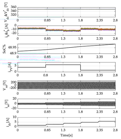
Figure 7.
Performance at the DC side under wind and solar irradiation change of the common DC-link voltage () and its reference ( ); ESS current ( ) and its reference ; the state of charge of the ESS (SoC%); the output PV current ( ); the stator voltage of the phase ‘a’ of the PMBLDCG ( ) and the current ( ); and the DC-WT current ( ).
One observes that the common DC-link voltage is well regulated and is following its reference, which is equal to 350 V and is not much affected when the system is subjected to sudden solar irradiation change at t = 0.8 s and t = 1.8 s, and when the wind speed suddenly increases at t = 0.85 s, t = 1.3 s, t = 1.8s, and t = 2.35 s, respectively. One observes that ESS currents follow its reference during weather condition changes. Seeing that the SoC% of ESS is less than 50% as detailed in Table 1 (operating mode 2), DG provides power to the connected linear load as shown in Figure 6 and charges the ESS. In addition, all generated power from the WT and PV panel is used to charge the ESS, which is why the ESS current varies with the variation of the WT and PV panel currents. One observes clearly that one extracts the MPP from the PV panel without using any power converter and from the WT using only a three-phase-diode bridge and boost converter. It is demonstrated that we can operate the WT efficiently under variable speed conditions and provide accurate and fast convergence to the maximum global operating point without speed sensors by applying the iterative interpolation method with perturbation and observation (P&O) technique. Based on the obtained results, one may conclude that the developed control for the DC-DC buck-boost converter shown in Figure 3, and the one for the DC-DC boost converter shown in Figure 2, operate well under all conditions without any saturation issue and with high efficiency.
4.3. Generated and Consumed Active and Reactive Powers
In Figure 8, the waveforms of active and reactive powers of DG (PDG, QDG), load (PL, QL), three-phase interfacing inverter (Pinv, Qinv), generated active power from WT (PW), and PV panel (PPV), and from the ESS (PESS), are demonstrated. One observes that the balance in power in the hybrid off-grid system is perfectly achieved, and all generated power in this operating mode (operating mode 2) is provided to the load and to charge the ESS because the SoC% is less than 50%. So, on the AC side, the DG is supplying the load directly and the difference of power is provided to the ESS through the three-phase interfacing inverter, which is why the active and reactive power is with a negative sign. On the DC side, all generated power from the WT and the PV array is used to charge the ESS, which is why the PESS is with a negative sign; it is increasing and decreasing based on the variation of the wind speed and solar irradiation. It is observed that the power balance is achieved without any issue, which confirms the robustness of the indirect control developed for the DC-DC buck-boost converter based on the double loop strategy.

Figure 8.
Global power demand and generation in the hybrid wind-PV-diesel off-grid system; theactive and reactive powers of DG (PDG, QDG), load (PL, QL), three-phase interfacing inverter (Pinv, Qinv), generated active power from WT (PW), and PV panel (PPV), and from the ESS (PESS).
4.4. Performance at PCC under the Presence of Nonlinear Loads
In Figure 9a and Figure 10a, the waveforms of the common DC voltage (Vdc) and its reference (Vdc*), currents of the phase ‘a’ of DG (), load (), and inverter () are demonstrated, and in Figure 9b,c and Figure 10b,c, the harmonic spectrum of load and DG currents are presented. One observes that the interfacing inverter acts as a power active filter under the presence of RL and RC both types of nonlinear loads. It compensates for harmonics and balances the DG current. One observes that the common DC-link voltage is maintained constant and follows its reference, which is equal to 350 V. One sees clearly from the spectra of harmonics shown in Figure 9b and Figure 10b the presence of the 5th and 7th order of harmonics in the load current. The total harmonics distortion (THD) of the load current is equal to 26.9% in Figure 9b for RC type nonlinear load and 26.05% in Figure 10b for RL type nonlinear load. The THD of the DG current as demonstrated in Figure 9c and Figure 10c is equal to 2.31% and 1.88%, respectively. This achieves the limit of IEEE Std 519-1992. One observes that the 5th and 7th order harmonics are mitigated at the level of DG current in the presence of both nonlinear loads. This proves that the stator of the SG is protected against 5th and 7th order harmonics under the presence of all nonlinear loads, which confirms the robustness of the SRF control with virtual impedance-based active damping, which is developed for the three-phase interfacing inverter.
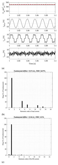
Figure 9.
(a) Waveforms of the DG, load, and inverter currents under the presence of nonlinear load type RC; (b) harmonic spectrum of load current; and (c) harmonic spectrum of DG current.
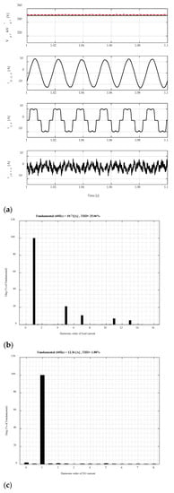
Figure 10.
(a) Waveforms of DG, load, and inverter currents under the presence of nonlinear load type RL; (b) harmonic spectrum of load current; and (c) harmonic spectrum of DG current.
4.5. Experimental Results of the DG under the Presence of Linear Load
Figure 11a–c show the performance of the DG under the presence of linear load. One observes that the terminal stator voltages (vDGab and vDGbc) are sinusoidal and regulated at their rated value, which equals 208 V at the primary of the transformer (element no. 5 in Figure 5 and 50 V at the secondary as shown in Figure 11c. The connected load is supplied with a constant current at a fixed frequency (i.e., 60 Hz). The DC current applied to the rotor winding of SG is constant and is equal to 0.8 A.
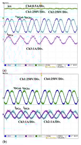
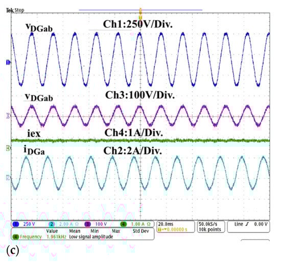
Figure 11.
Steady-state performance of (a) excitation current (iex), SG terminal stator voltages (vDGab, vDGbc) at the primary of the transformer and stator current (iDGa) of phase ‘a’; (b) SG terminal stator voltages (vDGab, vDGbc) at primary of transformer and stator currents (iDGa, iDGb) of phase ‘a’ and ‘b’; and (c) SG terminal stator voltage (vDGab) at primary of the transformer and at secondary (vDGab), excitation current (iex), and stator current (iDGa).
4.6. Performance under Load Variation and Presence of Linear Load
In Figure 12a–c, the waveforms of the common DC-link voltage (vdc), output DG current of phase ‘a’ (iDGa), the generated current from the PV panel and WT (iWT + iPV), load current of phase ‘a’ (iLa), ESS current (ib), and line PCC voltage (vLab) are presented. It is observed in Figure 12a that the load is suddenly connected to the system at t = 0.72 ms, and the DG stabilizes only after t = 0.12 s, and in this period, the ESS provides the difference. One observes that the common DC-link voltage is well regulated, and it is not affected during the transition, which confirms the robustness of the outer control loop of the DC-DC buck-boost converter. It is observed in Figure 12b, that ESS provides the difference of power between t = 0 s to t = 0.2 s, and the current becomes equal to zero when the load is disconnected at t = 0.2 s. In Figure 12c, the ESS current is increased more when the load is suddenly increased at t = 0.2 s. In all the cases, the load is supplied without interruption, and the power is balanced in the hybrid off-grid system. The common DC-link voltage is well regulated without deviation (overshoot and undershoot), which confirms the robustness of indirect control developed for the DC-DC buck-boost converter.
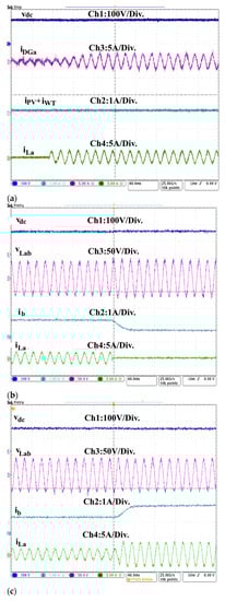
Figure 12.
Dynamic performance of system: (a) common DC-link voltage (vdc), DG current (iDGa) of phase ‘a’, sum of PV current and DC-WT current (iPV + iWT), and load current (iLa) of the phase ‘a’ at sudden switching ON of linear load at t = 0.08 s; (b) common DC-link voltage (vdc), load voltage of phase ‘a’ (vLab), ESS current (ib), and load current of phase ‘a’ (iLa) under sudden switching off of linear load at t = 0.2 s; and (c) common DC-link voltage (vdc), load voltage of phase ‘a’(vLab), ESS current (ib), and load current of phase ‘a’ (iLa) under sudden increasing of linear load at t = 0.2 s.
4.7. Performance in Presence of RC and RL Types Nonlinear Loads
In Figure 13a and Figure 14a, the common waveforms of DC-link voltage (vdc), load current of phase (iLa), DG current (iDGa), and the output inverter current (iinva) of phase ‘a’ in the presence of nonlinear loads type RL and type RC are presented. In Figure 13b,c and Figure 14b,c, the harmonics spectra of the load and DG currents are demonstrated. One observes clearly in Figure 13a and Figure 14a that the DG currents are sinusoidal and balanced in presence of the both type of nonlinear loads, and the common DC-link voltage is well regulated at its set value, which is equal to 120 V. It is observed that the inverter operates as an active filter; it mitigates harmonics and balances the DG current. This confirms the robustness of the proposed indirect control strategy for the DC-DC buck-boost converter and the SRF with a virtual impedance-based-active damping control strategy for the three-phase interfacing inverter. As demonstrated in Figure 13c and Figure 14c, the 5th and the 7th order harmonics are mitigated and THD of DG currents is less than 5% in the presence of both types of nonlinear loads, which confirms that the SG of the DG is protected against 5th and 7th order harmonics and proves the robustness of the developed control strategy for the three-phase interfacing inverter.
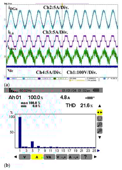
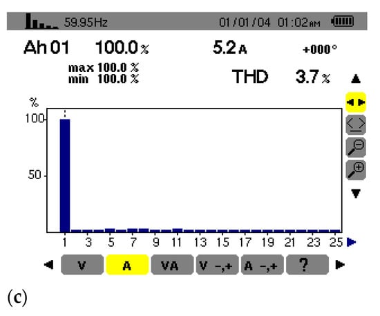
Figure 13.
(a) Performance in the presence of nonlinear load (RL type), (b) harmonic spectrum of load current, and (c) harmonic spectrum of DG current.
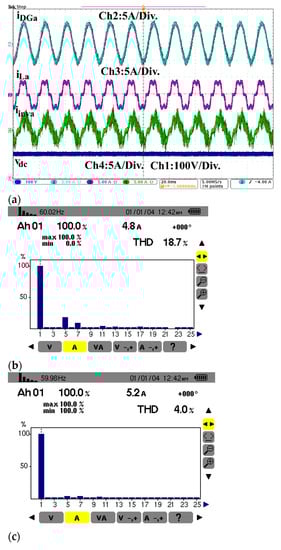
Figure 14.
(a) Performance in the presence of nonlinear load (RC type), (b) harmonic spectrum of load current, and (c) harmonic spectrum of DG current.
4.8. Performance of the WT at Wind Speed Change
The waveforms of the line PCC voltage (vLab), load current (iLa), output WT current at the DC side, and ESS current (ib) are presented in Figure 15. This test is realized by maintaining a constant load and applying different speeds to the PMBLDCG. One observes clearly that the output DC current, which is measured at the DC side of the WT, varies with the variation of the wind speed. Seeing that the DG is running at this time, the difference of generated power is taken by ESS. The ESS current is increased at t = 1.8 s and increased further at t = 3 s, t = 6 s, and at t = 12.2 s. One sees clearly that perturbation and observation (P&O) with variable steps of DC voltage based on the secant method performs well during wind variation, and all transitions are realized without any overshoot in current or voltage. It is observed that the PCC voltage is well regulated, and load is continually supplied without any interruption during the transition and during rotor speed variation. This proves the effective operation of the MPPT technique without sensing the rotor speed proposed for the variable speed wind turbine based on PMBLDCG.
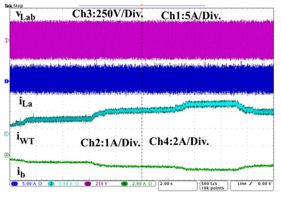
Figure 15.
Performance at the variation of wind speed at fixed linear load.
In Figure 16a, the waveforms of stator voltage (vsa) of phase ‘a’, WT output DC voltage (vWT) and current (iWT), and stator current (isa) of phase ‘a’ are presented. In Figure 16, (b) the zoomed waveforms of (a) between t = 2.64 s and t = 2.88 s are shown. One observes that experimental results are similar to the simulation results where the output DC voltage of the WT varies slightly with the variation of the wind speed. It is observed that the output stator current and the current measured at the output of three-phase diode-bridge increase at t = 0.8 s and increase more at t = 2.8 s with the increasing of the rotor speed. This validates the desired operation of the MPPT technique without mechanical speed measurement.
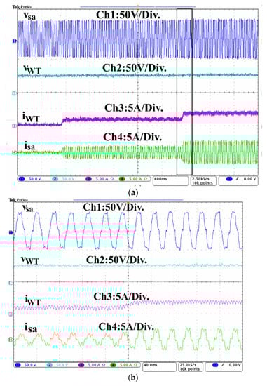
Figure 16.
Waveforms of WT side for: (a) stator voltage (vsa) of phase ‘a’, output DC voltage (vWT) and current (iWT), and stator current (isa) and (b) its zoomed waveform.
4.9. Performance of the PV Panel at Solar Irradiation Change
The waveforms of the PCC voltage (vDGa) of the phase ‘a’, the PV current (iPV), ESS current (ib), and the common DC link voltage are shown in Figure 17. This test is realized under solar irradiation change to test the performance of the proposed approach to achieve high efficiency from PV array without using any MPPT technique. One observes that the common DC-link voltage is regulated constant at its rated value, which is equal to the sum of the output voltage of the PVs connected in series. The system is subjected to solar irradiation change at t = 0.4 s, t = 0.72 s, and 1.16 s. One observes that by maintaining the common DC link voltage constant, one can easily extract the maximum of current from the PV panel during solar irradiation change. It is observed that the ESS current increases with the increase of the PV panel current, and Vdc is maintained constant; this proves the desired operation of the outer and inner control loops of the indirect control, which are designed to achieve MPPT from PV and balance the power in the off-grid system.
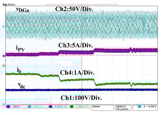
Figure 17.
Waveforms of PCC voltage (vDGa) at secondary of the transformer of output PV (iPV), ESS current (ib), and common DC link voltage (vdc).
5. Conclusions
The performance of the developed composite control strategy with reduced sensors for a PV-wind-diesel-based off-grid power generation system has been presented in this research work. The developed off-grid configuration has reduced the number of power converters to make it an effective, low-cost option. To achieve stable operation under disturbance and balance the power in the system, the developed control strategy for the DC-DC buck-boost converter is reinforced by the inner control loop. Furthermore, for better attenuation of switching harmonics without additional losses, active damping solution is developed and implemented. The obtained simulation and experimental results show satisfactory performance under the change in solar irradiation and wind speed, as well as balanced linear and nonlinear loads. It has been demonstrated that the perturbation and observation (P&O) technique with variable steps of DC voltage based on the secant method performs well during sudden wind speed variations without any saturation issue and use of mechanical speed sensor. The extraction of maximum power from PV panels without the MPPT algorithm has also been demonstrated. Furthermore, the control for a three-phase interfacing inverter using SRF control with virtual impedance-based active damping has been demonstrated to improve the power quality at PCC and power flow management in the system. In addition, the 5th and 7th order-harmonics are mitigated, and DG is operated perfectly without any challenge under the presence of nonlinear loads. Therefore, it is concluded that the developed composite control strategy for PV-wind-diesel-based off-grid power generation system performs well in the presence of severe real-time conditions. Up to now, the performance of the PV array has been tested under a fixed temperature of 25 °C and variable solar irradiation; therefore, the system efficiency under different temperatures needs evaluation. Furthermore, the high-frequency voltage stress on the DC side and the deterioration of the frequency and voltage stability under power imbalances need further evaluation.
Author Contributions
M.R. proposed the original idea and carried out the main research tasks, simulation, implementation, and writing. F.D. conducted experiments, and M.I. designed system elements. H.I. carried out formal analysis and reviews, A.C. and B.S. supervised and carried out reviews; S.S. performed the design of system element, writing, review, and editing. All authors have read and agreed to the published version of the manuscript.
Funding
This research received no external funding.
Institutional Review Board Statement
Not applicable.
Informed Consent Statement
Not applicable.
Data Availability Statement
Not applicable.
Acknowledgments
The authors wish to thank RQEI (Réseau québécois sur l’énergie intelligente) for their support.
Conflicts of Interest
The authors declare no conflict of interest.
Define Abbreviation
| Symbol | Description |
| WT | Wind turbine |
| PV | Photovoltaic array |
| ESS | Energy storage system |
| DG | Diesel generator |
| PMBLDCG | Permanent magnet brushless DC generator |
| isa, isb, and isc | Stator currents of the PMBLDCG |
| CWT | The capacitor at the output of the diode bridge |
| VWT | DC voltage of the WT |
| LWT | The inductor of the DC-DC boost converter for WT side |
| iWT | DC current of the WT |
| VPV | Output PV voltage |
| iPV | Output PV current |
| vb | Battery voltage |
| Lb | Inductor that connects the battery to the DC-DC buck-boost converter |
| Vdc | Common DC-link voltage |
| Vinva, Vinvb, and Vinvc | Output voltages of the interfacing inverter |
| iinva, iinvb, and iinvc | Output currents of the interfacing inverter |
| Vca, Vcb, and Vcc | Voltages of the output filter |
| Rc and CC | Resistance and capacitor of the output filter |
| icc | The current of the output filter |
| Linv and LDG | Inductors of the output filter |
| VLa, VLb, and VLc | Load voltages |
| iLa, iLb, and iLc | Load currents |
| iDGa, iDGb, and iDGc | Diesel generator currents |
| AVR | Automatic voltage regulator |
| DE | Diesel engine |
| P&O | Perturbation and observation technique |
| VWTmax | The maximum voltage obtained using the P&O technique |
| ΔVWT | Step of variation |
| VWT* | Reference DC voltage of the WT |
| ΔV | WT DC voltage error value |
| PI | Proportional integral regulator |
| iWT* | Reference DC current of the WT |
| ΔiWT | WT DC current error value |
| dWT | Control signal |
| S1 to S9 | Power electronic switches (insulated-gate bipolar transistor (IGBT)) of the power converters |
| PWM | Pulse-width modulation |
| Vdc* | Reference of the common DC-link voltage |
| ΔVdc | Error value of the common DC-link voltage |
| ib* | Reference battery current |
| Δ ib | Error value of battery current |
| db | Control signal |
| fs | System frequency |
| fs* | Reference of the system frequency |
| lLoss | losses of active power |
| d-q | Direct and quadrature axis |
| LPF | Low pass filter |
| PLL | Phased locked loop |
| ωt | Angular frequency |
| iDGa*, iDGb* and iDGc* | Reference of DG currents |
| G(s) | Transfer function of LCL filter |
References
- Hidalgo-Leon, R.; Amoroso, F.; Litardo, J.; Urquizo, J.; Torres, M.; Singh, P.; Soriano, G. Impact of the Reduction of Diesel Fuel Subsidy in the Design of an Off-Grid Hybrid Power System: A Case Study of the Bellavista Community in Ecuador. Energies 2021, 14, 1730. [Google Scholar] [CrossRef]
- Mokhtara, C.; Negrou, B.; Settou, N.; Settou, B.; Samy, M.M. Design optimization of off-grid Hybrid Renewable Energy Systems considering the effects of building energy performance and climate change: Case study of Algeria. Energy 2021, 219, 119605. [Google Scholar] [CrossRef]
- Dubuisson, F.; Rezkallah, M.; Ibrahim, H.; Chandra, A. Real-Time Implementation of the Predictive-Based Control with Bacterial Foraging Optimization Technique for Power Management in Standalone Microgrid Application. Energies 2021, 14, 1723. [Google Scholar] [CrossRef]
- Rezkallah, M.; Singh, S.; Chandra, A.; Singh, B.; Ibrahim, H. Off-Grid System Configurations for Coordinated Control of Renewable Energy Sources. Energies 2020, 13, 4950. [Google Scholar] [CrossRef]
- Rezkallah, M.; Chandra, A.; Singh, B.; Singh, S. Microgrid: Configurations, Control and Applications. IEEE Trans. Smart Grid 2017, 10, 1290–1302. [Google Scholar] [CrossRef]
- Sawle, Y.; Gupta, S.; Bohre, A.K. Review of hybrid renewable energy systems with comparative analysis of off-grid hybrid system. Renew. Sustain. Energy Rev. 2018, 81, 2217–2235. [Google Scholar] [CrossRef]
- Upadhyay, S.; Sharma, M. A review on configurations, control and sizing methodologies of hybrid energy systems. Renew. Sustain. Energy Rev. 2014, 38, 47–63. [Google Scholar] [CrossRef]
- Nehrir, M.H.; Wang, C.; Strunz, K.; Aki, H.; Ramakumar, R.; Bing, J.; Miao, Z.; Salameh, Z. A Review of Hybrid Renewable/Alternative Energy Systems for Electric Power Generation: Configurations, Control, and Applications. IEEE Trans. Sustain. Energy 2011, 2, 392–403. [Google Scholar] [CrossRef]
- Beleiu, H.G.; Maier, V.; Pavel, S.G.; Birou, I.; Pică, C.S.; Dărab, P.C. Harmonics Consequences on Drive Systems with Induction Motor. Appl. Sci. 2020, 10, 1528. [Google Scholar] [CrossRef] [Green Version]
- Rezkallah, M.; Chandra, A.; Ibrahim, H.; Singh, B. Implementation of Two-Level Control Coordinate for Seamless Transfer in Standalone Microgrid. In Proceedings of the 2019 IEEE Industry Applications Society Annual Meeting, Baltimore, MD, USA, 29 September–3 October 2019; Volume 75, pp. 1–6. [Google Scholar] [CrossRef]
- Park, B.; Jaehyeong, L.; Hangkyu, Y.; Gilsoo, J. Harmonic Mitigation Using Passive Harmonic Filters: Case Study in a Steel Mill Power System. Energies 2021, 14, 2278. [Google Scholar] [CrossRef]
- Hoon, Y.; Mohd, A.M.R.; Muhammad, A.A.M.Z.; Mohamad, A.M.Z. Shunt active power filter: A review on phase synchronization control techniques. Electronics 2019, 8, 7. [Google Scholar] [CrossRef] [Green Version]
- Bielecka, A.; Wojciechowski, D. Stability Analysis of Shunt Active Power Filter with Predictive Closed-Loop Control of Supply Current. Energies 2021, 14, 2208. [Google Scholar] [CrossRef]
- Bhim, S.; Chandra, A.; Kamal, A.L.-H. Power Quality: Problems and Mitigation Techniques; John Wiley & Sons: Hoboken, NJ, USA, 2014. [Google Scholar]
- Mehmood, S.; Qureshi, A.; Kristensen, A.S. Risk Mitigation of Poor Power Quality Issues of Standalone Wind Turbines: An Efficacy Study of Synchronous Reference Frame (SRF) Control. Energies 2020, 13, 4485. [Google Scholar] [CrossRef]
- Singh, B.; Sharma, S. SRF theory for voltage and frequency control of IAG based wind power generation. In Proceedings of the International Conference on Power Systems, Kharagpur, India, 27–29 December 2009; IEEE: Piscataway, NJ, USA, 2009; pp. 1–6. [Google Scholar]
- Naderipour, A.; Asuhaimi Mohd Zin, A.; Bin Habibuddin, M.H.; Miveh, M.R.; Guerrero, J.M. An improved synchronous reference frame current control strategy for a photovoltaic grid-connected inverter under unbalanced and nonlinear load conditions. PLoS ONE 2017, 12, e0164856. [Google Scholar] [CrossRef] [PubMed] [Green Version]
- Benhalima, S.; Miloud, R.; Chandra, A. Real-Time Implementation of Robust Control Strategies Based on Sliding Mode Control for Standalone Microgrids Supplying Non-Linear Loads. Energies 2018, 11, 2590. [Google Scholar] [CrossRef] [Green Version]
- Lopez-Santos, O.; Urrego-Aponte, J.O.; Lezama, S.T.; Almansa-López, J.D. Control of the Bidirectional Buck-Boost Converter Operating in Boundary Conduction Mode to Provide Hold-Up Time Extension. Energies 2018, 11, 2560. [Google Scholar] [CrossRef] [Green Version]
- Ramos-Paja, C.A.; Bastidas-Rodríguez, J.D.; González, D.; Acevedo, S.; Peláez-Restrepo, J. Design and Control of a Buck–Boost Charger-Discharger for DC-Bus Regulation in Microgrids. Energies 2017, 10, 1847. [Google Scholar] [CrossRef] [Green Version]
- Yu, S.Y.; Kim, H.J.; Kim, J.H.; Han, B.M. SoC-based output voltage control for BESS with a lithium-ion battery in a stand-alone DC microgrid. Energies 2016, 11, 924. [Google Scholar] [CrossRef] [Green Version]
- Zhu, Y.; Kim, M.K.; Wen, H. Simulation and Analysis of Perturbation and Observation-Based Self-Adaptable Step Size Maximum Power Point Tracking Strategy with Low Power Loss for Photovoltaics. Energies 2018, 12, 92. [Google Scholar] [CrossRef] [Green Version]
- Rezkallah, M.; Hamadi, A.; Chandra, A.; Singh, B. Design and Implementation of Active Power Control With Improved P&O Method for Wind-PV-Battery-Based Standalone Generation System. IEEE Trans. Ind. Electron. 2017, 65, 5590–5600. [Google Scholar] [CrossRef]
- Jung, Y.; So, J.; Yu, G.; Choi, J. Improved perturbation and observation method (IP&O) of MPPT control for photovoltaic power systems. In Proceedings of the Conference Record of the Thirty-First IEEE Photovoltaic Specialists Conference, Lake Buena Vista, FL, USA, 3–7 January 2005; pp. 1788–1791. [Google Scholar]
- Gunasekaran, M.; Krishnasamy, V.; Selvam, S.; Almakhles, D.J.; Anglani, N. An Adaptive resistance perturbation based MPPT algorithm for Photovoltaic applications. IEEE Access 2020, 8, 1. [Google Scholar] [CrossRef]
- Pathak, G.; Singh, B.; Panigrahi, B.K. Isolated microgrid employing PMBLDCG for wind power generation and synchronous reluctance generator for DG system. In Proceedings of the 2014 IEEE 6th India International Conference on Power Electronics (IICPE), Kurukshetra, India, 8–10 December 2014; pp. 1–6. [Google Scholar]
- Sharma, R.; Singh, B. MDSOGI-FLL Control for SyRG-PMBLDCG-BES-PV Based Microgrid. In Proceedings of the IEEE Industrial and Commercial Power Systems Europe, Genova, Italy, 11–14 June 2019; pp. 1–6. [Google Scholar]
- Pathak, G.; Singh, B.; Panigrahi, B.K. Control of Wind-Diesel Microgrid Using Affine Projection-Like Algorithm. IEEE Trans. Ind. Inform. 2016, 12, 524–531. [Google Scholar] [CrossRef]
- Chen, Y.-M.Y.; Liu, C.S.; Hung, C.; Cheng, C.-S. Multi-input inverter for grid-connected hybrid PV/wind power system. IEEE Trans. Power Electron. 2007, 2, 1070–1077. [Google Scholar] [CrossRef]
- Chun, S.; Kwasinski, A. Analysis of classical root-finding methods applied to digital maximum power point tracking for sustainable photovoltaic energy generation. IEEE Trans. Power Electron. 2011, 26, 3730–3743. [Google Scholar] [CrossRef]
- Hosseini, S.H.; Farakhor, A.; Haghighian, S.K. Novel algorithm of maximum power point tracking (MPPT) for variable speed PMSG wind generation systems through model predictive control. In Proceedings of the 2013 8th International Conference on Electrical and Electronics Engineering (ELECO), Bursa, Turkey, 28–30 November 2013; pp. 243–247. [Google Scholar]
- Rezkallah, M.; Chandra, A.; Saad, M.; Tremblay, M.; Singh, B.; Singh, S.; Ibrahim, H. Composite Control Strategy for a PV-Wind-Diesel based Off-Grid Power Generation System Supplying Unbalanced Non-Linear Loads. In Proceedings of the 2018 IEEE Industry Applications Society Annual Meeting (IAS), Portland, OR, USA, 23–27 September 2018; pp. 1–6. [Google Scholar]
- Rezkallah, M.; Chandra, A.; Saad, M.; Tremblay, M.; Singh, B.; Singh, S.; Ibrahim, H. Design and Implementation of Decentralized Control for Distributed generation based Off-grid System. In Proceedings of the 2020 IEEE International Conference on Power Electronics, Smart Grid and Renewable Energy (PESGRE2020), Cochin, India, 2–4 January 2020; pp. 1–6. [Google Scholar]
- Bao, C.; Ruan, X.; Wang, X.; Li, W.; Pan, D.; Weng, K. Step-by-Step Controller Design for LCL-Type Grid-Connected Inverter with Capacitor–Current-Feedback Active-Damping. IEEE Trans. Power Electron. 2014, 29, 1239–1253. [Google Scholar] [CrossRef]
- Liu, F.; Zhou, Y.; Duan, S.; Yin, J.; Liu, B.; Liu, F. Parameter Design of a Two-Current-Loop Controller Used in a Grid-Connected Inverter System with LCL Filter. IEEE Trans. Ind. Electron. 2009, 56, 4483–4491. [Google Scholar] [CrossRef]
Publisher’s Note: MDPI stays neutral with regard to jurisdictional claims in published maps and institutional affiliations. |
© 2021 by the authors. Licensee MDPI, Basel, Switzerland. This article is an open access article distributed under the terms and conditions of the Creative Commons Attribution (CC BY) license (https://creativecommons.org/licenses/by/4.0/).