
Isolation Microgrid Design for Remote Areas with the Integration of Renewable Energy: A Case Study of Con Dao Island in Vietnam


Abstract
:
1. Introduction
2. Overview of the Microgrid
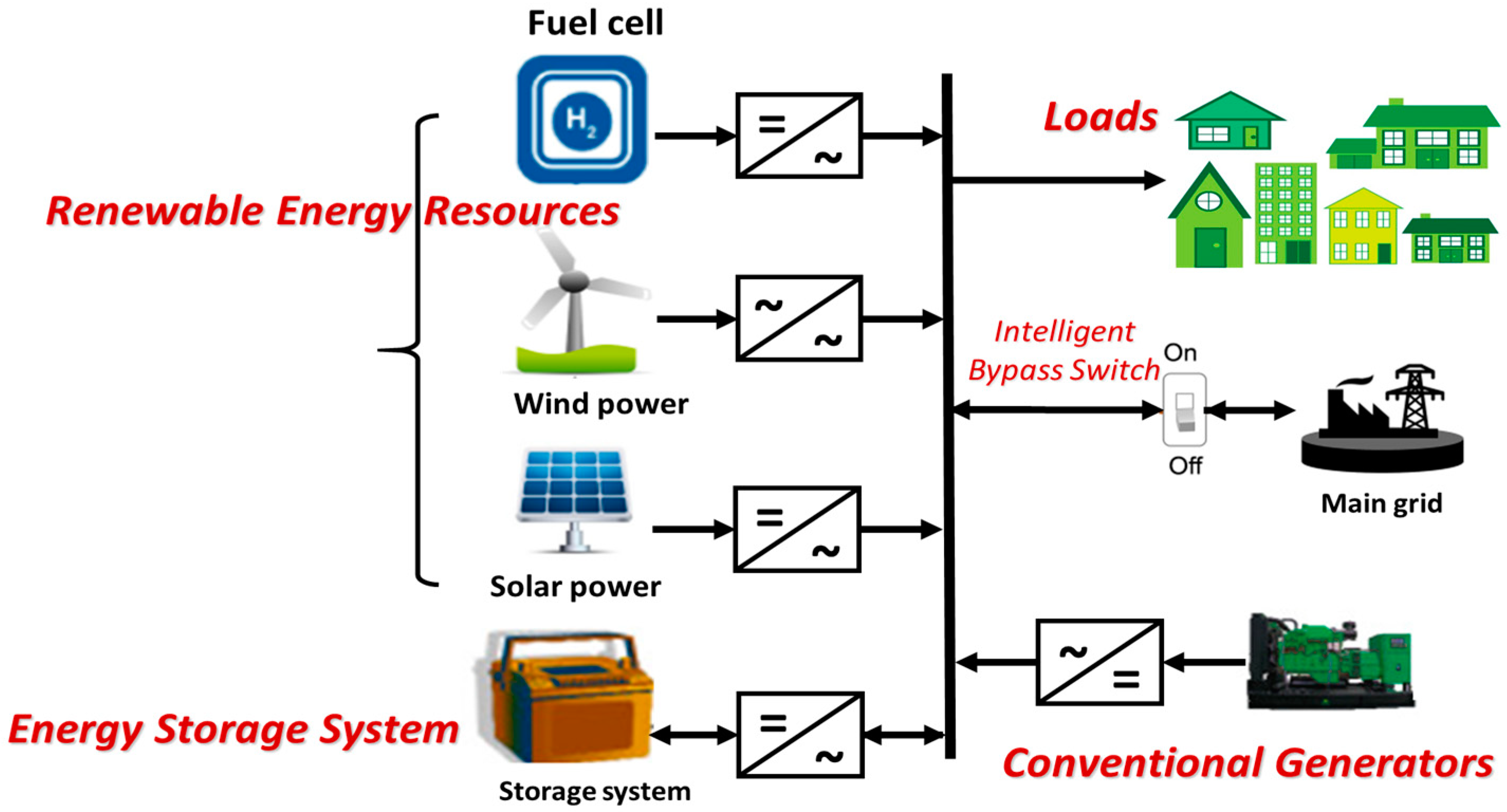
2.1. Microgrid Defination
2.2. Microgrid Operation Modes
- -
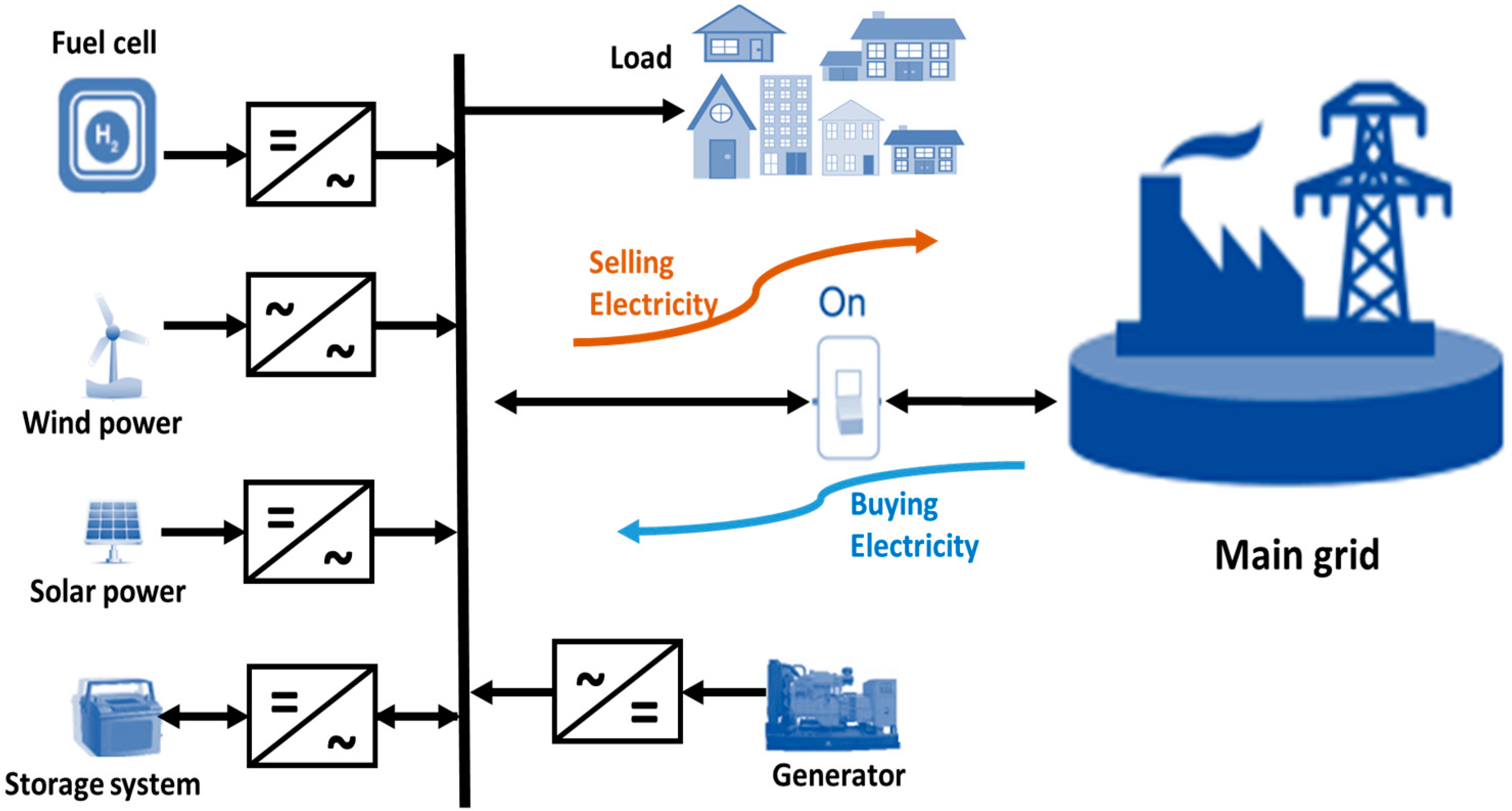
- Grid-connected operation mode: The MG is interconnected to the main network. This operating mode is divided into two types: grid connection but not supplying excess power to the grid, and grid connected but providing excess power back to the grid. The frequency of MG is synchronized with the frequency of the main grid without any technical problems. If the load is high and the distributed sources in the MG cannot meet the demand, the main grid will support the supply through the PCC. In this mode, the MG grid is guaranteed to operate safely even if distributed sources fail [30,31]. Figure 2 depicts the grid-connected microgrid model.
- -
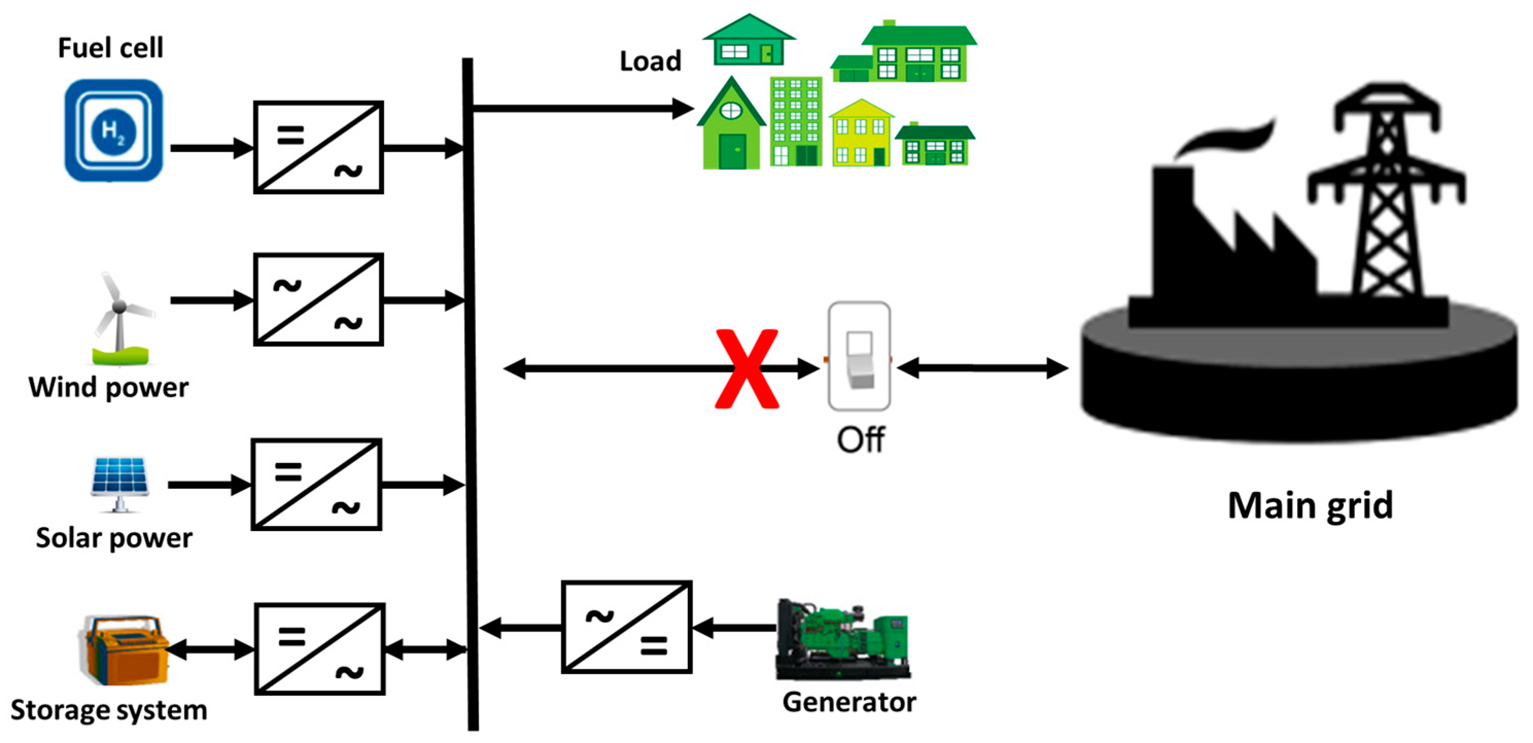
- Islanded operating mode: The MG, when not connected to the main grid, is called a stand-alone MG. This operating model is commonly applied to grids built in mountainous areas, on islands, or in completely isolated areas, where the main grid cannot supply electricity. The model is also applied when the main power grid fails and cannot supply power to an area [32,33]. The island separation of a small grid system helps reduce power outages, ensure the safe operation of the fault grid area, and improve the quality of power supply services. The disadvantage of this model is that the power source depends mainly on distributed energy sources, is unstable, and often changes suddenly depending on weather conditions. Figure 3 depicts the model of an islanded microgrid.
2.3. Microgrid Control
- -
- Primary control: Usually designed to ensure voltage and frequency stability for microgrids and adjust the power sharing among distributed generators. This level of control also helps minimize circulation currents between paralleled converters of three-phase generators, causing overcurrent in electrical equipment.
- -
- Secondary control: The function of this control level is to compensate for the voltage and frequency difference left by the primary control. This level of control has slower dynamics than the primary level, and is performed to satisfy power quality requirements.
- -
- Tertiary control, also known as the energy management system: This is the final control level that regulates the power of the MG, and between the MG and the main network. The third level of control also provides an economically optimal operation to minimize the electricity costs.
2.4. Energy Management in MG
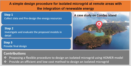
3. A Methodology for Designing Microgrid Using HOMER
- -
- Stage 1—Design of distributed energy sources: The objective of this stage is to evaluate the feasibility of the designed system. Questions that need to be answered at this stage include: How much backup power does the model need? This includes a rough assessment of operating costs and how that changes the design paradigm.
- -
- Stage 2—Detailed design: At this stage, the design options are narrowed down and focused on concretizing the equipment for the design model. It is necessary to update the data about the supplier’s products, thereby refining the design by comparing supplier’s information.
- -
- Stage 3—Final design: At this stage of the project, the contractor will produce detailed technical drawings and address site-specific issues such as equipment size, wiring, protection scheme, and construction challenges.
3.1. Model of Power Supply Components in the MG
- -
- Wind turbine model: Data related to wind speed are needed to calculate the power output (PWT) of a wind turbine at each time t. The wind speed is measured over 24 h considering the minimum wind speed to put the turbine into operation (cut-in wind speed), and the maximum wind speed that must stop the turbine from running (cut-out wind speed) [2].
- PR: wind turbine’s rated power
- V: wind speed
- Vci: cut-in wind speed
- Vco: cut-out wind speed
- -
- PV model: Solar power generation at date i, time t can be modeled according to the following equation [41]:
- Am: Solar panel surface area (m2)
- ηm: Module efficiency
- ηConv: Power conversion efficiency
- Tr: Reference temperature of the solar cell
- βt: Heat coefficient
- Gt: Solar irradiance (W/m2)
- Tc: Solar cell temperature
- -
- Microturbine model: To assess the cost of a microturbine, two main cost components are considered: fuel cost Cfuel and maintenance cost CO&M at time t
- -
- Battery model: The battery energy at date i, time t will be calculated based on the following equation [42]:
- Vbat: Battery’s nominal voltage
- Cbat: nominal capacity of the battery (Ah)
- SOC: Battery’s stage of charge, which can be calculated in the following equation:
- δ: Capacity available in battery
- ηch: Charging efficiency of the battery
- k: battery’s status. k = 1 while charging and k = 0 while discharging
- Ibat: Charging current
3.2. Optimization Problem for Designing Microgrid
- X is the variable;
- fi(X) is the objective function;
- G(X) and H(X) are constraint functions;
- Ω represents the space of possible solutions.
- CAnnual,Total represents the annual cost
- Rproject represents the life of the project
- J represents the annual interest
- Eprimary: Energy supplied to the base load
- Edef: Energy supplied to slow loads
- Egrid, sell: Energy sold to the grid
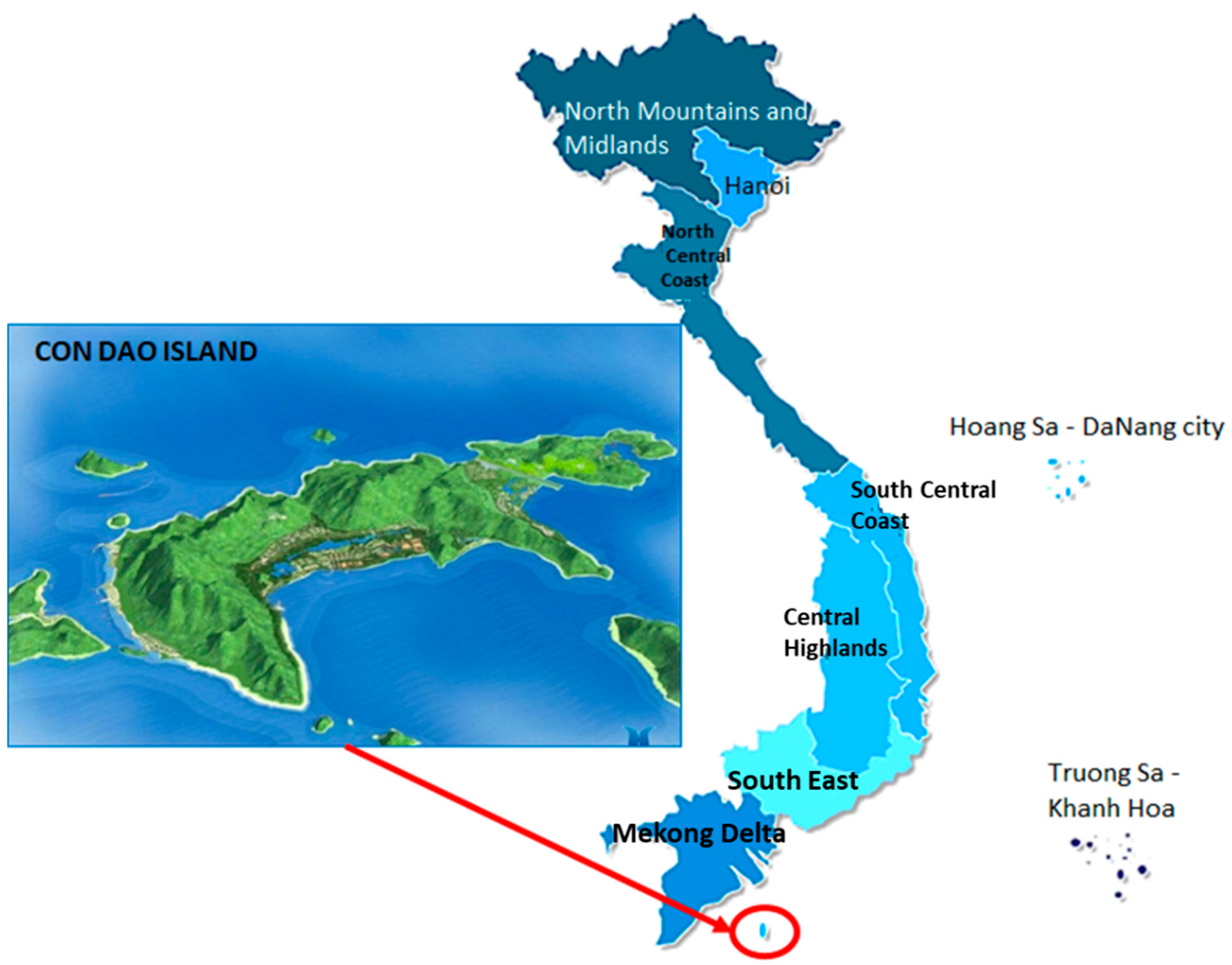
4. An Application for Designing Isolation Microgrid in Con Dao Island, Vietnam
4.1. Application
- -
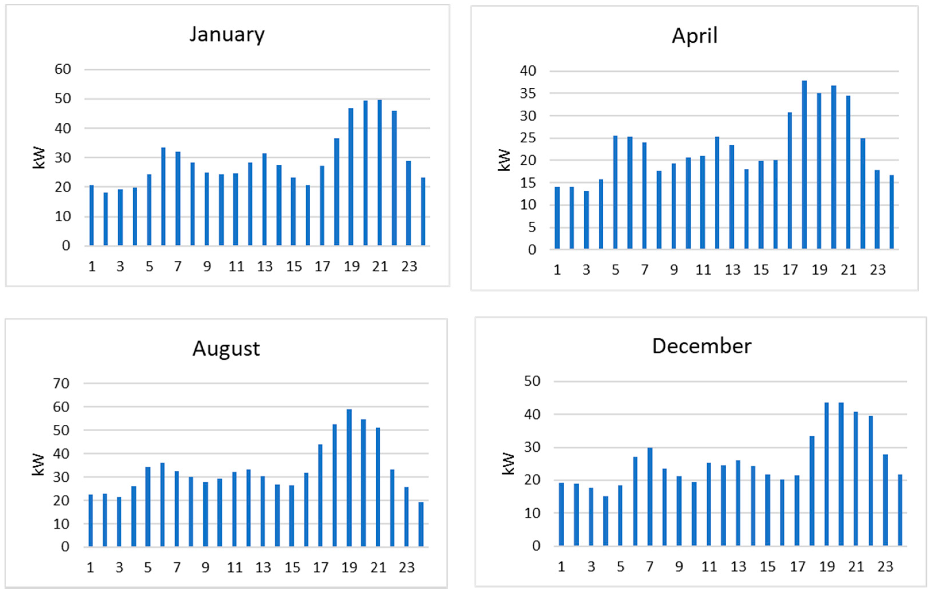
- Daily estimations of energy usage: The daily energy capacity in the considered area is about 623 kWh, the peak load capacity of the day is about 60 kW. The graph of load profiles is shown in Figure 7.
- -
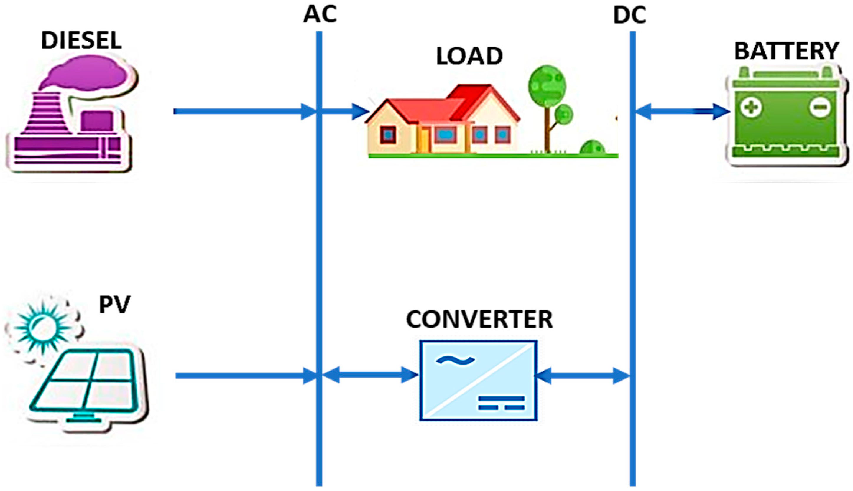
- The model of diesel generator: The simulated diesel generator has a fixed capacity of 40 kW. The capital cost of the generator is is USA 8000, its replacement cost is USD 15,000, and it has a lifetime of 15,000 h [48]. The model will run with different scenarios with and without a diesel generator to check if it is necessary to install this generator in the MG. The model of the generator is shown in Figure 8.
- -
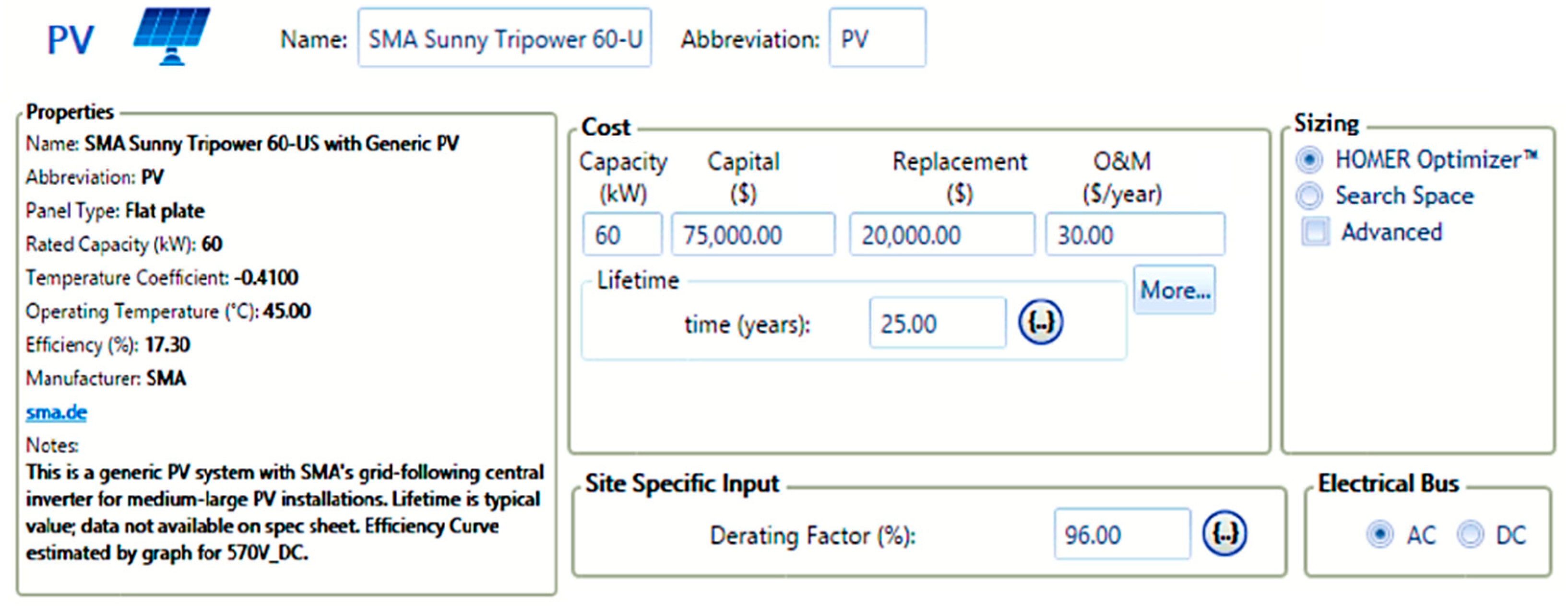
- Model of PV system: The power output of the solar system is estimated based on the size of PV system, in addition to the temperature and solar energy data at the considered location. The solar irradiance, temperature, and clearness index at Con Dao island were imported from National Renewable Energy Laboratory (NREL) resources [49]. Figure 9 shows the monthly average solar irradiance and clearness index for Con Dao.
- -
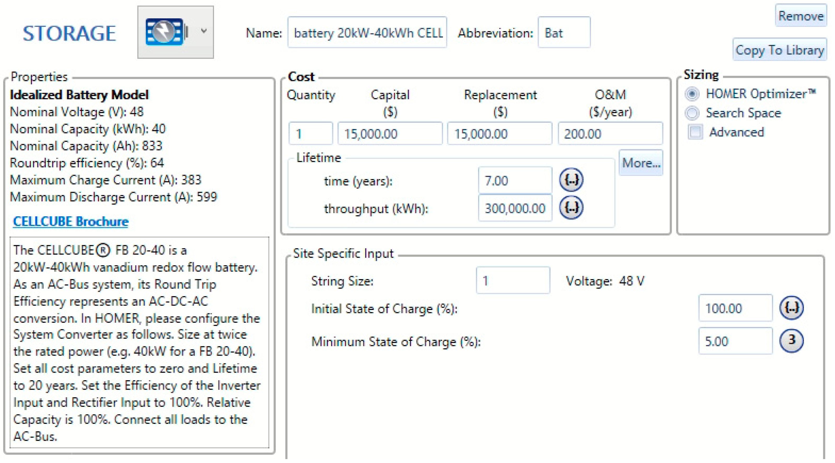
- Model of the battery: The battery is used to store excess energy from the PV system at peak times and then supply electricity to the load when the system is out of power. The battery is modelled using vanadium redox flow battery specifications with a 40 kWh capacity. The capital cost is USD 15,000, replacement cost is USD 15,000, and the lifetime of the battery is 7 years [51,52]. The model of the battery is designed to find the optimal amount of battery for the system. The model is shown in Figure 11.
- -
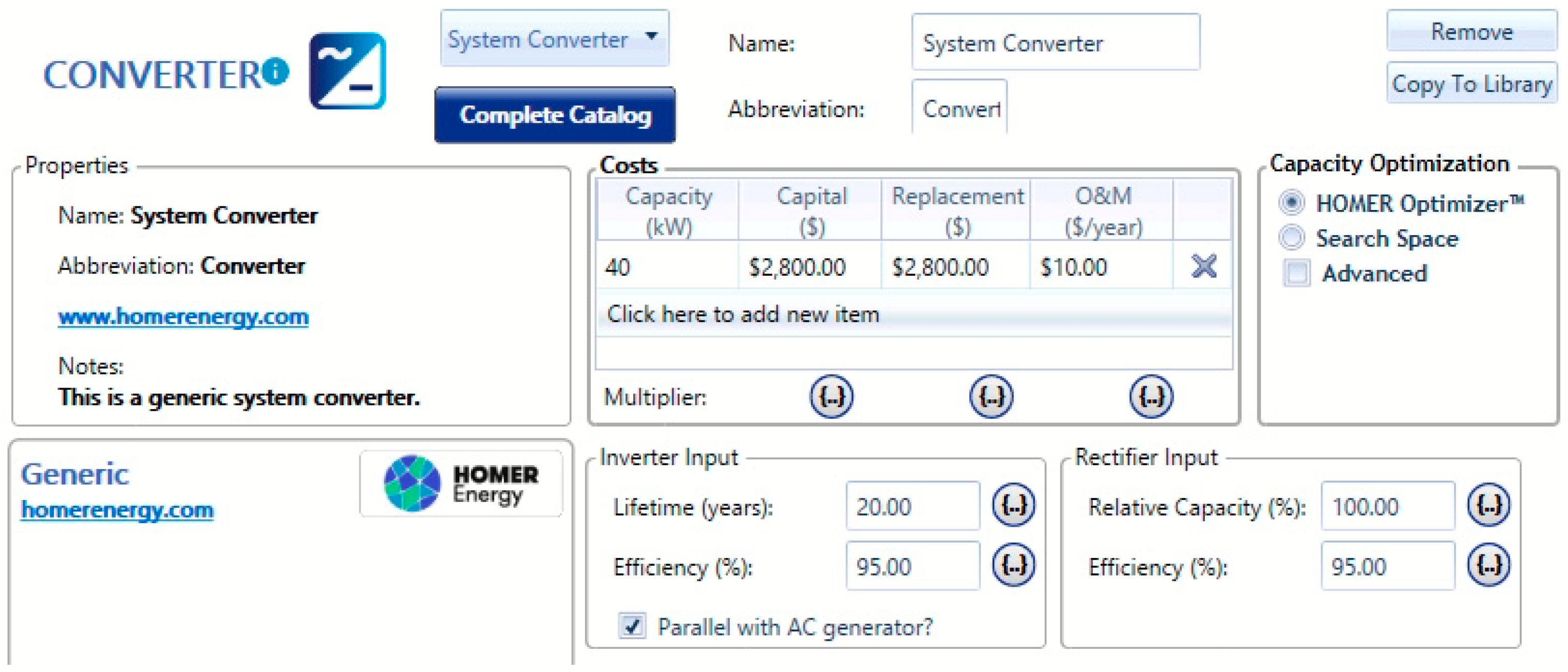
- Converter model: Converters are used to convert DC to AC and vice versa. The size of the inverter represents the amount of electrical power received from the AC system to be converted to DC power. The capital cost and replacement cost of the converter are the same, i.e., USD 2800 [53]. Its lifespan is 20 years. The model is shown in Figure 12.
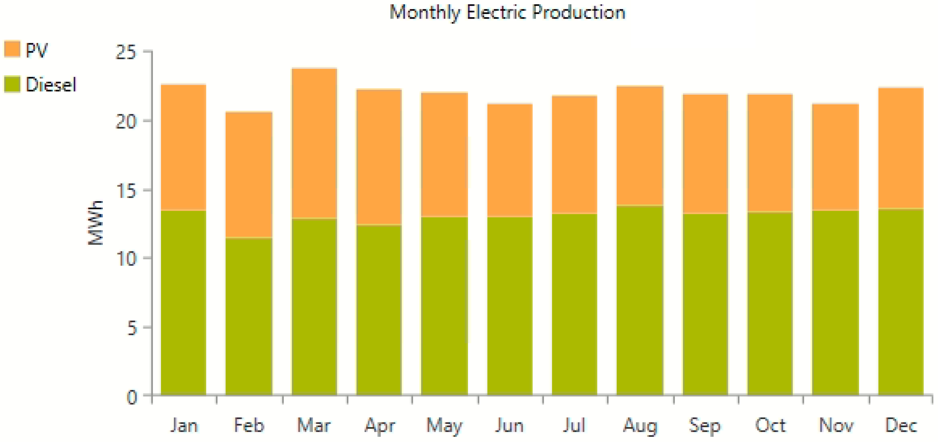
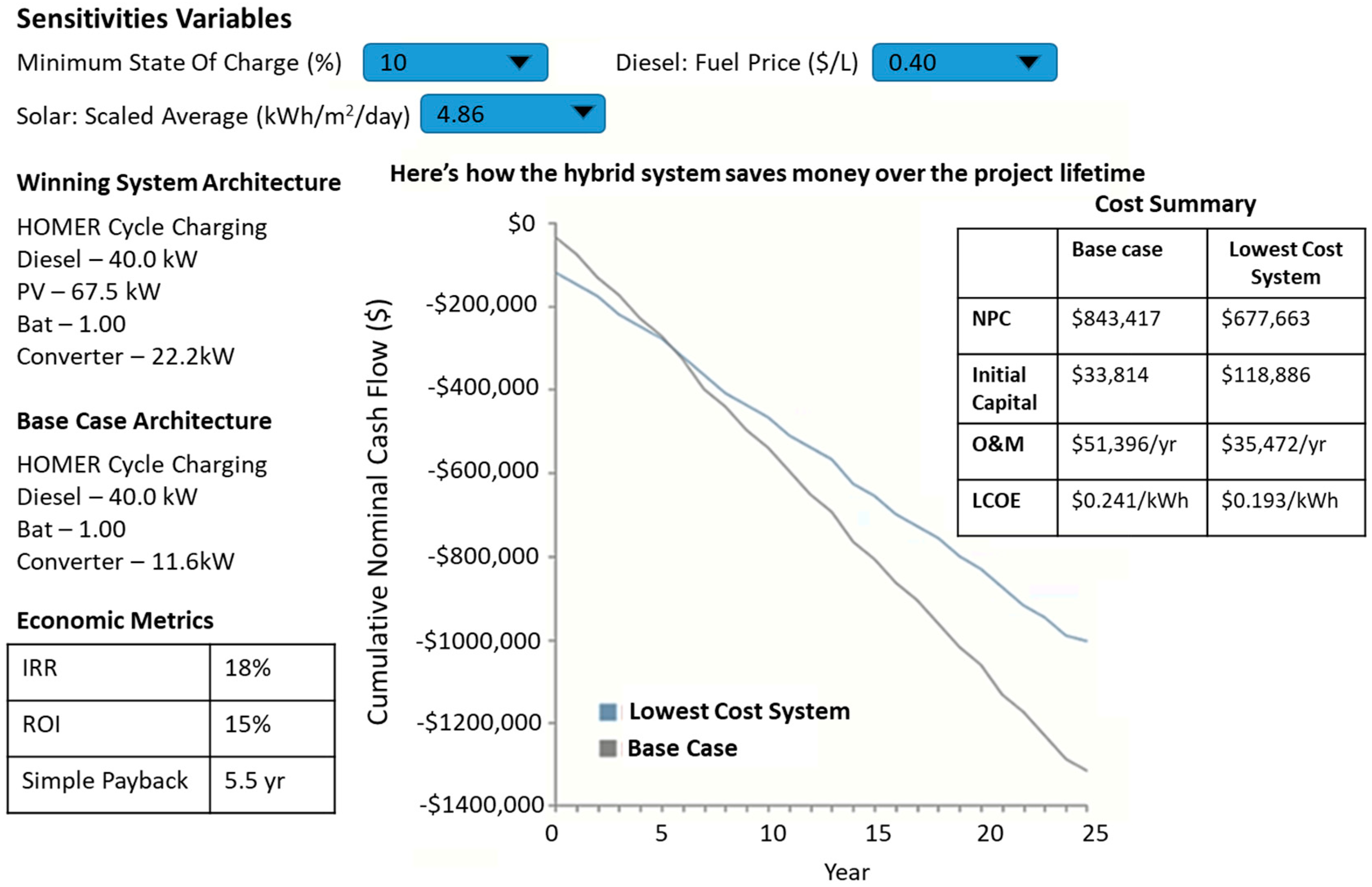
4.2. Results Analysis
5. Discussion
6. Conclusions
Author Contributions
Funding
Institutional Review Board Statement
Informed Consent Statement
Acknowledgments
Conflicts of Interest
References
- Khan, N.; Kalair, E.; Abas, N.; Kalair, A. Energy transition from molecules to atoms and photons. Eng. Sci. Technol. Int. J. 2018, 22, 185–214. [Google Scholar] [CrossRef]
- Shahinzadeh, H.; Moazzami, M.; Fathi, S.; Gharehpetian, G.B. Optimal sizing and energy management of a grid-connected microgrid using HOMER software. In Proceedings of the 2016 Smart Grids Conference (SGC), Kerman, Iran, 20–21 December 2016; pp. 1–6. [Google Scholar] [CrossRef]
- Medvedkina, Y.; Khodochenko, A. Renewable Energy and Their Impact on Environmental Pollution in the Context of Globalization. In Proceedings of the 2020 International Multi-Conference on Industrial Engineering and Modern Technologies (FarEastCon), Vladivostok, Russian, 6–9 October 2020; pp. 1–4. [Google Scholar] [CrossRef]
- Hoarca, I.C.; Bizon, N.; Enescu, F.M. Using the potential of renewable energy sources in Romania to reduce environmental pollution. In Proceedings of the 2021 13th International Conference on Electronics, Computers and Artificial Intelligence (ECAI), Pitesti, Romania, 1–3 July 2021; pp. 1–6. [Google Scholar] [CrossRef]
- Nichols, M.R. How Rural Areas Can Benefit from Renewable Energy. Available online: https://www.altenergymag.com/article/2017/05/how-rural-areas-can-benefit-from-renewable-energy/26257/ (accessed on 10 September 2021).
- Ton, D.T.; Smith, M.A. The US department of energy’s microgrid initiative. Electr. J. 2012, 25, 84–94. [Google Scholar] [CrossRef]
- Hirsch, A.; Parag, Y.; Guerrero, J. Microgrids: A review of technologies, key drivers, and outstanding issues. Renew. Sustain. Energy Rev. 2018, 90, 402–411. [Google Scholar] [CrossRef]
- Nojavan, S.; Majidi, M.; Esfetanaj, N.N. An efficient cost-reliability optimization model for optimal siting and sizing of energy storage system in a microgrid in the presence of responsible load management. Energy 2017, 139, 89–97. [Google Scholar] [CrossRef]
- Rokni, S.G.M.; Radmehr, M.; Zakariazadeh, A. Optimum energy resource scheduling in a microgrid using a distributed algorithm framework. Sustain. Cities Soc. 2018, 37, 222–231. [Google Scholar] [CrossRef]
- Aghamohammadi, M.R.; Abdolahinia, H. A new approach for optimal sizing of battery energy storage system for primary frequency control of islanded Microgrid. Int. J. Electr. Power Energy Syst. 2014, 54, 325–333. [Google Scholar] [CrossRef]
- Zimon, D.; Tyan, J.; Sroufe, R. Drivers of sustainable supply chain management: Practices to alignment with un sustainable development goals. Int. J. Qual. Res. 2020, 14, 219–236. [Google Scholar] [CrossRef]
- Allen, C.; Metternicht, G.; Wiedmann, T. Initial progress in implementing the Sustainable Development Goals (SDGs): A review of evidence from countries. Sustain. Sci. 2018, 13, 1453–1467. [Google Scholar] [CrossRef]
- Fan, Z.; Fan, B.; Liu, W. Distributed Control of DC Microgrids for Optimal Coordination of Conventional and Renewable Generators. IEEE Trans. Smart Grid 2021, 12, 4607–4615. [Google Scholar] [CrossRef]
- Fan, Z.; Fan, B.; Peng, J.; Liu, W. Operation Loss Minimization Targeted Distributed Optimal Control of DC Microgrids. IEEE Syst. J. 2020, 1–11. [Google Scholar] [CrossRef]
- Nasser, N.; Fazeli, M. Buffered-Microgrid Structure for Future Power Networks; a Seamless Microgrid Control. IEEE Trans. Smart Grid 2020, 12, 131–140. [Google Scholar] [CrossRef]
- Espina, E.; Llanos, J.; Burgos-Mellado, C.; Cardenas-Dobson, R.; Martinez-Gomez, M.; Saez, D. Distributed Control Strategies for Microgrids: An Overview. IEEE Access 2020, 8, 193412–193448. [Google Scholar] [CrossRef]
- Zacharia, L.; Tziovani, L.; Savva, M.; Hadjidemetriou, L.; Kyriakides, E.; Bintoudi, A.; Tsolakis, A.; Tzovaras, D.; Martinez-Ramos, J.L.; Marano, A.; et al. Optimal Energy Management and Scheduling of a Microgrid in Grid-Connected and Islanded Modes. In Proceedings of the 2019 International Conference on Smart Energy Systems and Technologies (SEST), Porto, Portugal, 9–11 September 2019; pp. 1–6. [Google Scholar] [CrossRef]
- Wang, J.; Wang, M.; Li, H.; Qin, W.; Wang, L. Energy Management Strategy for Microgrid Including Hybrid Energy Storage. In Proceedings of the 2018 Asian Conference on Energy, Power and Transportation Electrification (ACEPT), Singapore, 30 October–2 November 2018; pp. 1–6. [Google Scholar] [CrossRef]
- Mathiesen, P.; Stadler, M.; Kleissl, J.; Pecenak, Z. Techno-economic optimization of islanded microgrids considering intra-hour variability. Appl. Energy 2021, 304, 117777. [Google Scholar] [CrossRef]
- Zhu, X.; Premrudeepreechacharn, S.; Sorndit, C.; Meenual, T.; Kasirawat, T.; Tantichayakorn, N. Design and Development of a Microgrid Project at Rural Area. In Proceedings of the 2019 IEEE PES GTD Grand International Conference and Exposition Asia (GTD Asia), Bangkok, Thailand, 19–23 March 2019; pp. 877–882. [Google Scholar] [CrossRef]
- Namaganda-Kiyimba, J.; Mutale, J. An Optimal Rural Community PV Microgrid Design Using Mixed Integer Linear Programming and DBSCAN Approach. SAIEE Afr. Res. J. 2020, 111, 111–119. [Google Scholar] [CrossRef]
- Osama, R.A.; Zobaa, A.F.; Abdelaziz, A.Y. A Planning Framework for Optimal Partitioning of Distribution Networks into Microgrids. IEEE Syst. J. 2019, 14, 916–926. [Google Scholar] [CrossRef] [Green Version]
- Hafez, O.; Bhattacharya, K. Optimal planning and design of a renewable energy based supply system for microgrids. Renew. Energy 2012, 45, 7–15. [Google Scholar] [CrossRef]
- Fernando, W.; Gupta, N.; Linn, H.H.; Ozveren, C.S. Design of optimum configuration of a hybrid power system for Abertay University campus. In Proceedings of the 2018 IEEE Conference of Russian Young Researchers in Electrical and Electronic Engineering (EIConRus), Moscow and St. Petersburg, Russia, 29 January–1 February 2018; pp. 1795–1800. [Google Scholar] [CrossRef]
- Tito, S.; Lie, T.T.; Anderson, T.N. A simple sizing optimization method for wind-photovoltaic-battery hybrid renewable energy systems. In Proceedings of the 20th Electronics New Zealand Conference, Massey University, Albany Campus, Auckland, New Zealand, 5–6 September 2013; pp. 8–12. [Google Scholar]
- Meng, L.; Savaghebi, M.; Andrade, F.; Vasquez, J.C.; Guerrero, J.M.; Graells, M. Microgrid central controller development and hierarchical control implementation in the intelligent microgrid lab of Aalborg University. In Proceedings of the 2015 IEEE Applied Power Electronics Conference and Exposition (APEC), Charlotte, NC, USA, 15–19 March 2015; pp. 2585–2592. [Google Scholar] [CrossRef] [Green Version]
- Palizban, O.; Kauhaniemi, K. Hierarchical control structure in microgrids with distributed generation: Island and grid-connected mode. Renew. Sustain. Energy Rev. 2015, 44, 797–813. [Google Scholar] [CrossRef]
- Tran, Q.T.; Di Silvestre, M.L.; Sanseverino, E.R.; Zizzo, G.; Pham, T.N. Driven Primary Regulation for Minimum Power Losses Operation in Islanded Microgrids. Energies 2018, 11, 2890. [Google Scholar] [CrossRef] [Green Version]
- Sanseverino, E.R.; Tran, Q.T.T.; Di Silvestre, M.L.; Zizzo, G.; Doan, B.V. Minimum power losses by using droop coefficients regulation method with voltage and frequency constraints in islanded microgrids. In Proceedings of the 2018 IEEE International Energy Conference (ENERGYCON), Limassol, Cyprus, 3–7 June 2018; pp. 1–6. [Google Scholar] [CrossRef]
- Gabbar, H.A.; Abdelsalam, A.A. Microgrid energy management in grid-connected and islanding modes based on SVC. Energy Convers. Manag. 2014, 86, 964–972. [Google Scholar] [CrossRef]
- Joseph, V.; Thomas, P.C.; Joseph, V. Grid connected mode of microgrid with reactive power compensation. In Proceedings of the 2013 International Conference on Advanced Computing and Communication Systems, Coimbatore, India, 19–21 December 2013; pp. 1–6. [Google Scholar] [CrossRef]
- Kulkarni, S.V.; Gaonkar, D.N. Operation and control of a microgrid in isolated mode with multiple distributed generation systems. In Proceedings of the 2017 International Conference on Technological Advancements in Power and Energy (TAP Energy), Kollam, India, 21–23 December 2017; pp. 1–6. [Google Scholar] [CrossRef]
- Fusheng, L.; Ruisheng, L.; Fengquan, Z. Chapter 6—Monitoring and energy management of the microgrid. In Microgrid Technology and Engineering Application; Fusheng, L., Ruisheng, L., Fengquan, Z., Eds.; Academic Press: Oxford, UK, 2016; pp. 91–113. [Google Scholar]
- Guerrero, J.; Vasquez, J.C.; Matas, J.; de Vicuña, L.G.; Castilla, M. Hierarchical Control of Droop-Controlled AC and DC Microgrids—A General Approach toward Standardization. IEEE Trans. Ind. Electron. 2010, 58, 158–172. [Google Scholar] [CrossRef]
- Zia, M.F.; Elbouchikhi, E.; Benbouzid, M. Microgrids energy management systems: A critical review on methods, solutions, and prospects. Appl. Energy 2018, 222, 1033–1055. [Google Scholar] [CrossRef]
- Kowalczyk, A.; Wlodarczyk, A.; Tarnawski, J. Microgrid energy management system. In Proceedings of the 2016 21st International Conference on Methods and Models in Automation and Robotics (MMAR), Miedzyzdroje, Poland, 29 August–1 September 2016; pp. 157–162. [Google Scholar] [CrossRef]
- Lilienthal, P. Three Phases in Designing Successful Microgrid Projects. Available online: https://microgridnews.com/three-phases-in-designing-successful-microgrid-projects/ (accessed on 10 September 2021).
- Khormali, S.; Niknam, E. Operation Cost Minimization of Domestic Microgrid under the Time of Use Pricing Using HOMER. In Proceedings of the 2019 20th International Scientific Conference on Electric Power Engineering (EPE), Kouty, Czech Republic, 15–17 May 2019; pp. 1–6. [Google Scholar] [CrossRef]
- Dutta, S.; Qian, A.; Adhikari, A.; Yue, W.; Yufan, Z.; Zhaoyu, L. Modelling and Cost Optimization of an Islanded Microgrid with an Existing Microhydro using HOMER Software. In Proceedings of the 2019 2nd Asia Conference on Energy and Environment Engineering (ACEEE), Hiroshima, Japan, 8–10 June 2019; pp. 74–78. [Google Scholar] [CrossRef]
- Krishna, K.M. Optimization analysis of Microgrid using HOMER A case study. In Proceedings of the 2011 Annual IEEE India Conference, Hyderabad, India, 16–18 December 2011; pp. 1–5. [Google Scholar] [CrossRef]
- Pawar, N.; Nema, P. Techno-Economic Performance Analysis of Grid Connected PV Solar Power Generation System Using HOMER Software. In Proceedings of the 2018 IEEE International Conference on Computational Intelligence and Computing Research (ICCIC), Madurai, India, 13–15 December 2018; pp. 1–5. [Google Scholar] [CrossRef]
- Gautam, J.; Ahmed, I.; Kumar, P. Optimization and Comparative Analysis of Solar-Biomass Hybrid Power Generation System Using Homer. In Proceedings of the 2018 International Conference on Intelligent Circuits and Systems (ICICS), Phagwara, India, 19–20 April 2018; pp. 397–400. [Google Scholar] [CrossRef]
- Yadav, D.K.; Girimaji, S.P.; Bhatti, T. Optimal hybrid power system design using HOMER. In Proceedings of the 2012 IEEE 5th India International Conference on Power Electronics (IICPE), Delhi, India, 6–8 December 2012; pp. 1–6. [Google Scholar] [CrossRef]
- Manmadharao, S.; Chaitanya, S.N.V.S.K.; Rao, B.V.; Srinivasarao, G. Design and Optimization of Grid Integrated Solar Energy System Using HOMER GRID software. In Proceedings of the 2019 Innovations in Power and Advanced Computing Technologies (i-PACT), Vellore, India, 22–23 March 2019; Volume 1, pp. 1–5. [Google Scholar] [CrossRef]
- Con Dao Island, Heaven on Earth. Available online: https://www.tonkin-travel.com/vietnam/places-detail/con-dao-island-heaven-on-earth.html (accessed on 10 September 2021).
- Ha, T Con Dao Islands to Access National Power Grid. Vnexpresss. Available online: https://e.vnexpress.net/news/news/con-dao-islands-to-access-national-power-grid-4252773.html (accessed on 10 September 2021).
- Sanseverino, E.R.; Tran, Q.T.T.; Van, B.D.; Le, H.T.T.; Quang, N.N. Challenges and Opportunities for Renewable-Based Microgrids Integration in Vietnam. In Innovations in Land, Water and Energy for Vietnam’s Sustainable Development; Anderle, M., Ed.; Springer International Publishing: Cham, Switzerland, 2021; pp. 109–127. [Google Scholar]
- KVA Perkings Diesel Generator. Available online: https://litestoreusa.com/index.php?id_product=6919&id_product_attribute=0&rewrite=triton-tp-p30-t1-60-30-kw-40-kva-perkings-diesel-generator&controller=product&gclid=CjwKCAjw_L6LBhBbEiwA4c46uvajgNNlUCw-AedgCMXn1Acu-ImLSt2w7nTtmarwP3Ntl86jOdbmYxoC_7UQAvD_BwE (accessed on 10 September 2021).
- NSRDB Data Viewer. Available online: https://maps.nrel.gov/nsrdb-viewer/?aL=x8CI3i%255Bv%255D%3Dt%26Jea8x6%255Bv%255D%3Dt%26Jea8x6%255Bd%255D%3D1%26VRLt_G%255Bv%255D%3Dt%26VRLt_G%255Bd%255D%3D2%26mcQtmw%255Bv%255D%3Dt%26mcQtmw%255Bd%255D%3D3&bL=clight&cE=0&lR=0&mC=4.740675384778373%2C22.8515625&zL=2 (accessed on 15 September 2021).
- Flat Roof Commercial Building Solar Panel Systems. Available online: https://www.solarelectricsupply.com/commercial-solar-systems/flat-roof (accessed on 15 September 2021).
- Smart Grid Battery: Redox Flow Battery. Available online: https://www.betterworldsolutions.eu/smart-grid-battery-redox-flow-battery/ (accessed on 15 September 2021).
- How Much do Home Batteries Cost? Available online: https://www.energysage.com/energy-storage/should-you-get-storage/how-much-do-batteries-cost/ (accessed on 15 September 2021).
- 40 kw Solar Inverter. Available online: https://www.alibaba.com/showroom/40kw-solar-inverter.html (accessed on 15 September 2021).


| Load | Number of Units | Consumption Energy (Watts) | Time (Hours) | Total Energy (Wh) |
|---|---|---|---|---|
| Domestic Lighting | 3 | 30 | 12 | 75,600 |
| Fans | 2 | 40 | 10 | 56,000 |
| Refrigeration | 1 | 100 | 14 | 98,000 |
| Television | 1 | 400 | 12 | 336,000 |
| Radio | 1 | 22 | 12 | 18,480 |
| Other loads | 1 | 40 | 14 | 39,200 |
| Total | 623,280 | |||
| Minimum State of Charge (%) | Diesel Fuel Price ($/L) | Solar Scaled Average (kWh/m2/day) | PV (kW) | Diesel (kW) | Battery | Converter (kW) | NPC ($) | |
|---|---|---|---|---|---|---|---|---|
| 1 | 10 | 0.4 | 2 | 98.72 | 40 | 1 | 21.76 | 768,245.80 |
| 2 | 20 | 0.4 | 2 | 92.74 | 40 | 1 | 34.72 | 773,242.80 |
| 3 | 5 | 0.4 | 2 | 97.10 | 40 | 1 | 23.52 | 767,418.70 |
| 4 | 10 | 0.4 | 4.863 | 67.47 | 40 | 1 | 22.15 | 677,662.60 |
| 5 | 20 | 0.4 | 4.863 | 100.88 | 40 | 1 | 27.60 | 691,798.60 |
| 6 | 5 | 0.4 | 4.863 | 68.74 | 40 | 1 | 22.17 | 677,201.00 |
| 7 | 10 | 0.6 | 2 | 118.47 | 40 | 1 | 22.78 | 980,418.10 |
| 8 | 20 | 0.6 | 2 | 116.65 | 40 | 1 | 21.79 | 981,539.30 |
| 9 | 5 | 0.6 | 2 | 117.69 | 40 | 1 | 22.26 | 979,611.20 |
| 10 | 10 | 0.6 | 4.863 | 76.87 | 40 | 1 | 22.50 | 872,892.50 |
| 11 | 20 | 0.6 | 4.863 | 79.43 | 40 | 1 | 21.81 | 873,540.50 |
| 12 | 5 | 0.6 | 4.863 | 79.91 | 40 | 1 | 22.06 | 872,801.60 |
| 13 | System with only diesel generator | 0 | 40 | 1 | 11.6 | 843,417.00 | ||
| 14 | System with only PV | 1330 | 0 | 26 | 172 | 2.8 M | ||
Publisher’s Note: MDPI stays neutral with regard to jurisdictional claims in published maps and institutional affiliations. |
© 2021 by the authors. Licensee MDPI, Basel, Switzerland. This article is an open access article distributed under the terms and conditions of the Creative Commons Attribution (CC BY) license (https://creativecommons.org/licenses/by/4.0/).
Share and Cite
Tran, Q.T.; Davies, K.; Sepasi, S. Isolation Microgrid Design for Remote Areas with the Integration of Renewable Energy: A Case Study of Con Dao Island in Vietnam. Clean Technol. 2021, 3, 804-820. https://doi.org/10.3390/cleantechnol3040047
Tran QT, Davies K, Sepasi S. Isolation Microgrid Design for Remote Areas with the Integration of Renewable Energy: A Case Study of Con Dao Island in Vietnam. Clean Technologies. 2021; 3(4):804-820. https://doi.org/10.3390/cleantechnol3040047
Chicago/Turabian StyleTran, Quynh T., Kevin Davies, and Saeed Sepasi. 2021. "Isolation Microgrid Design for Remote Areas with the Integration of Renewable Energy: A Case Study of Con Dao Island in Vietnam" Clean Technologies 3, no. 4: 804-820. https://doi.org/10.3390/cleantechnol3040047
APA StyleTran, Q. T., Davies, K., & Sepasi, S. (2021). Isolation Microgrid Design for Remote Areas with the Integration of Renewable Energy: A Case Study of Con Dao Island in Vietnam. Clean Technologies, 3(4), 804-820. https://doi.org/10.3390/cleantechnol3040047