Article

Nonlinear Dynamics of a Coupled Electromechanical Transmission

by
Antonio Zippo
1,*,
Moslem Molaie
2 and
Francesco Pellicano
1
1
Department of Engineering “Enzo Ferrari”, Centre InterMech MoRe, University of Modena and Reggio Emilia, 41125 Modena, Italy
2
Department of Engineering “Enzo Ferrari”, University of Modena and Reggio Emilia, 41125 Modena, Italy
*
Author to whom correspondence should be addressed.
Vibration 2025, 8(3), 34; https://doi.org/10.3390/vibration8030034
Submission received: 7 May 2025 / Revised: 12 June 2025 / Accepted: 16 June 2025 / Published: 20 June 2025
(This article belongs to the Special Issue Nonlinear Vibration of Mechanical Systems)

Abstract

:
The mechanical connection between a transmission system and an electric motor gives rise to a strong interaction between their respective dynamics. In particular, the coupling between an electric motor and a nonlinear spur gear transmission significantly influences the overall dynamic behavior of the integrated system. This study presents a detailed investigation into the electromechanical coupling effects between a permanent magnet synchronous machine (PMSM) and a nonlinear spur gear transmission. To focus on these effects, three configurations are analyzed: (i) a standalone gear pair model without motor interaction, (ii) a combined gear–motor system without dynamic coupling, and (iii) a fully coupled electromechanical system where the mechanical feedback influences motor control. The dynamic interaction between the motor’s torsional vibrations and the gear transmission is captured using the derivative of the transmission error as a feedback signal, enabling a closed-loop electromechanical model. Numerical simulations highlight the critical role of this coupling in shaping system dynamics, offering insights into the stability and performance of electric drive–gear transmission systems under different operating conditions. It also underscores the limitations of traditional modeling approaches that neglect feedback effects from the mechanical subsystem. The findings contribute to a more accurate and comprehensive understanding of coupled motor–gear dynamics, which is essential for the design and control of advanced electromechanical transmission systems in high-performance applications.

1. Introduction

The automotive industry is undergoing a significant transformation with the rapid adoption of electrified powertrains, where permanent magnet synchronous motors play a pivotal role due to their high efficiency, power density, and controllability.
PMSMs are increasingly used in various applications, particularly in electric vehicles and industrial settings, due to their favorable characteristics, including high power density, high efficiency, and superior dynamic performance. PMSMs do not suffer from the drawbacks associated with DC motors, such as maintenance needs and lower robustness, which makes them a preferable choice for a multitude of applications [1,2]. The intrinsic advantages of PMSMs manifest in their high torque-to-weight ratio and the capability for precise speed control [3]. For instance, they demonstrate exceptional performance in servo applications where fast response times and high acceleration are critical [1,4]. Moreover, the application range of PMSMs is expanding, including their integration into renewable energy systems, aerospace technology, and medical devices, showcasing their versatility [5]. This increasing implementation necessitates a focus on improving efficiency and reducing operational noise, aspects that are vital in demanding applications like electric vehicles, where energy efficiency and user comfort are paramount [6,7]. However, integrating PMSMs with mechanical gear systems introduces complex electromechanical coupling phenomena that can adversely affect vehicle performance, particularly in terms of torque ripple, vibrations, and acoustic noise. Gear transmissions themselves are a source of noise and vibration, as with planetary gear transmission, where excessive noise and vibration can be indicators of poor load-sharing and phasing. These issues can lead to reduced system performance, increased wear, and potentially catastrophic failure if left unaddressed [8]. Electromechanical coupling refers to the bidirectional interaction between the electrical dynamics of the motor and the mechanical characteristics of the gear system. In automotive applications, this coupling becomes critical as factors such as gear backlash, meshing stiffness, and torsional vibrations can influence the motor’s electromagnetic behavior, leading to challenges in control and noise mitigation. Therefore, a comprehensive understanding of this coupling is essential for accurate modeling, robust control design, and fault diagnosis in advanced electromechanical systems. One of the main disturbances is due to torque ripple in PMSMs, which is a well-known issue that leads to vibrations and acoustic noise, affecting the vehicle’s noise, vibration, and harshness (NVH) performance. Various methods have been proposed to minimize torque ripple, including current modulation techniques and rotor design optimizations. Jedryczka et al. [9] presented a method for torque ripple minimization by modulating phase currents, demonstrating significant reductions in torque ripple levels.
In the context of automotive applications, torque ripple and radial electromagnetic (EM) vibrations are critical concerns. Dai et al. [10] focused on an 8-pole, 36-slot Integrated Starter Generator (ISG) motor optimized using a combination of Q-axis and magnetic bridge notching (QMC notch), as well as segmented rotor skewing, to reduce torque ripple and radial EM vibration; their results showed that the QMC notch significantly reduces torque ripple, while skewing designs greatly diminish radial EM vibrations. Another technique that is useful to suppress the dynamic load of the integrated electric drive system is an active damping control strategy [11]; in the considered work, the disturbances were caused by the sudden step electromagnetic torque during rapid acceleration. Overall, the interaction between PMSMs and gear systems introduces complex electromechanical coupling dynamics that cannot be neglected. Jiang et al. studied the electromechanical coupling torsional resonance characteristics of a multistage gear transmission system driven by a low-speed and high-power PMSM, considering the PMSM electromagnetic effect and bending–torsional vibration characteristics [12]. Their findings emphasized the importance of considering the effect of the electromechanical coupling on the design and analysis of such systems. In hybrid electric vehicles (HEVs), the dual-motor electric drive system (DEDS) presents additional challenges as the electromechanical coupling dynamics of the DEDS, including the PMSM and the gear transmission system, considering time-varying mesh stiffness of gears and the nonlinear characteristics of inverters [13]. The dynamic characteristics of the coupled electromechanical system were simulated and analyzed in single-motor and dual-motor drive modes under steady-state and impact conditions.
Furthermore, the influence of torque ripple on the motor–gear system, considering rotor-step skewing, was investigated. A coupled electromechanical model was proposed to investigate the vibration characteristics, highlighting the significance of rotor design in mitigating electromechanical coupling effects [14]. The key issue is the accurate modeling of electromechanical coupling that has become essential for developing effective control strategies. A new method was proposed to analyze electromechanical coupling vibration, emphasizing that speed and dynamic meshing force are the main factors affecting forced vibration [15]. Additionally, another study introduced a dynamic model of a gear transmission system driven by a motor, considering the lubrication and friction characteristics, to define the electromechanical dynamic behavior [16]. In [17], a passive control strategy is proposed to suppress torsional vibrations resulting from electromechanical coupling, focusing on a multi-stable nonlinear energy sink that mitigates these fluctuations; while in [18], a PMSM torque ripple suppression method based on a self-adaptive mutation algorithm (SMA)-optimized iterative learning control (ILC) was presented. The advantage of this method is that it is not necessary to have prior knowledge of the system and motor parameters. This approach effectively reduces torque ripples, leading to improved motor performance. Another relevant aspect is represented by experimental validation and simulation studies, which are crucial for understanding electromechanical coupling effects. An evaluation of torque ripple and tooth forces of a skewed PMSM was conducted using 2D and 3D finite-element (FE) simulations. The study compared various skewing configurations, analyzing torque ripple amplitudes and tooth forces, which significantly impact a vehicle’s NVH behavior [19].
Recent advancements in modeling electromechanical coupling phenomena have significantly improved the understanding of integrated motor–gear systems. For instance, studies have demonstrated that coupling the electromagnetic characteristics of motors with mechanical vibrations of gears and shafts can reveal intricate dynamic behaviors such as resonance risks, nonlinear modal interactions, and time-varying excitation effects. A dynamic model combining a nonlinear permeance network of a squirrel-cage induction motor with a planetary gear system, for example, was used to explore how machine slotting, magnetic saturation, and mesh stiffness (MS) influence system behavior under internal excitations [20]. Similarly, other investigations have shown that the magnetic field of induction machines introduces additional vibration modes and alters the torsional response of gear components, emphasizing the importance of integrated analysis to predict resonance regions [21]. Particularly in electric vehicles and hybrid electric vehicles, electromechanical coupling is further complicated by nonlinearities arising from permanent magnet synchronous motors, control systems, and meshing interfaces. Research in this area has established that electromagnetic harmonics and mechanical excitations jointly shape the frequency content of both current signals and dynamic responses, often manifesting in complex phenomena such as mode transitions, resonance amplifications, and jump instabilities under transient operating conditions [13,22]. Furthermore, the presence of unbalanced magnetic pull (UMP) in PMSMs, due to field asymmetries and rotor misalignment, has been shown to induce softening stiffness behavior and unstable dynamic regions, thereby motivating the need for robust modeling frameworks to accurately predict and mitigate such effects [23]. Despite these advances, challenges remain in achieving a unified and computationally efficient framework that can simultaneously capture the electromagnetic nonlinearity, dynamic gear meshing behavior, and coupling effects under realistic working conditions. Many of the existing studies either rely on reduced-order representations of the electrical subsystem or overlook the back-coupling effects that mechanical deformations impose on motor performance. There is a growing demand for multibody simulation approaches that integrate high-fidelity motor models with flexible gear transmission dynamics, enabling better design, diagnosis, and control of advanced electromechanical systems.
This paper aims to investigate the electromechanical coupling between PMSMs and gear pairs, highlighting the differences through the comparison of three configurations in the modeling that accounts for both electrical and mechanical nonlinearities. The focus will be on capturing the dynamic interactions under varying load and speed conditions, exploring their implications for control performance. Particular attention will be paid to torque ripple and resonant phenomena.

2. Dynamical Model

The electromechanical coupling in spur gear systems plays a pivotal role in shaping the dynamic behavior and overall efficiency of these systems. This coupling primarily arises from the interaction between the torsional vibrations of the electric motor and those of the gear transmission. Gaining a clear understanding of this interaction is vital for evaluating the operational stability and performance of gear transmissions. In this work, we investigate a spur gear pair, as depicted in Figure 1, to explore the influence of electromechanical coupling on transmission dynamics. In particular, the mechanical output speed is employed as a feedback signal to regulate the motor’s power output, thus establishing a closed-loop interaction between the electrical and mechanical subsystems. Although many earlier studies model the motor and gear train as a unified system, they often overlook the feedback effect exerted by the mechanical subsystem on the motor. In contrast, this study formulates the nonlinear governing equations of gear transmission, develops an independent model for the electrical drive, and subsequently integrates them to reflect the coupled dynamics. To emphasize the role of this interaction, we construct and compare three alternative models: (i) a purely mechanical gear model that excludes motor influence; (ii) a motor–gear system without dynamic coupling where the feedback from the gear transmission is not considered, called in this work combined model; and (iii) a fully coupled motor-gear system that considers the effect of the gear transmission. The dynamic responses of all three configurations are then analyzed to thoroughly assess the impact of electromechanical coupling.

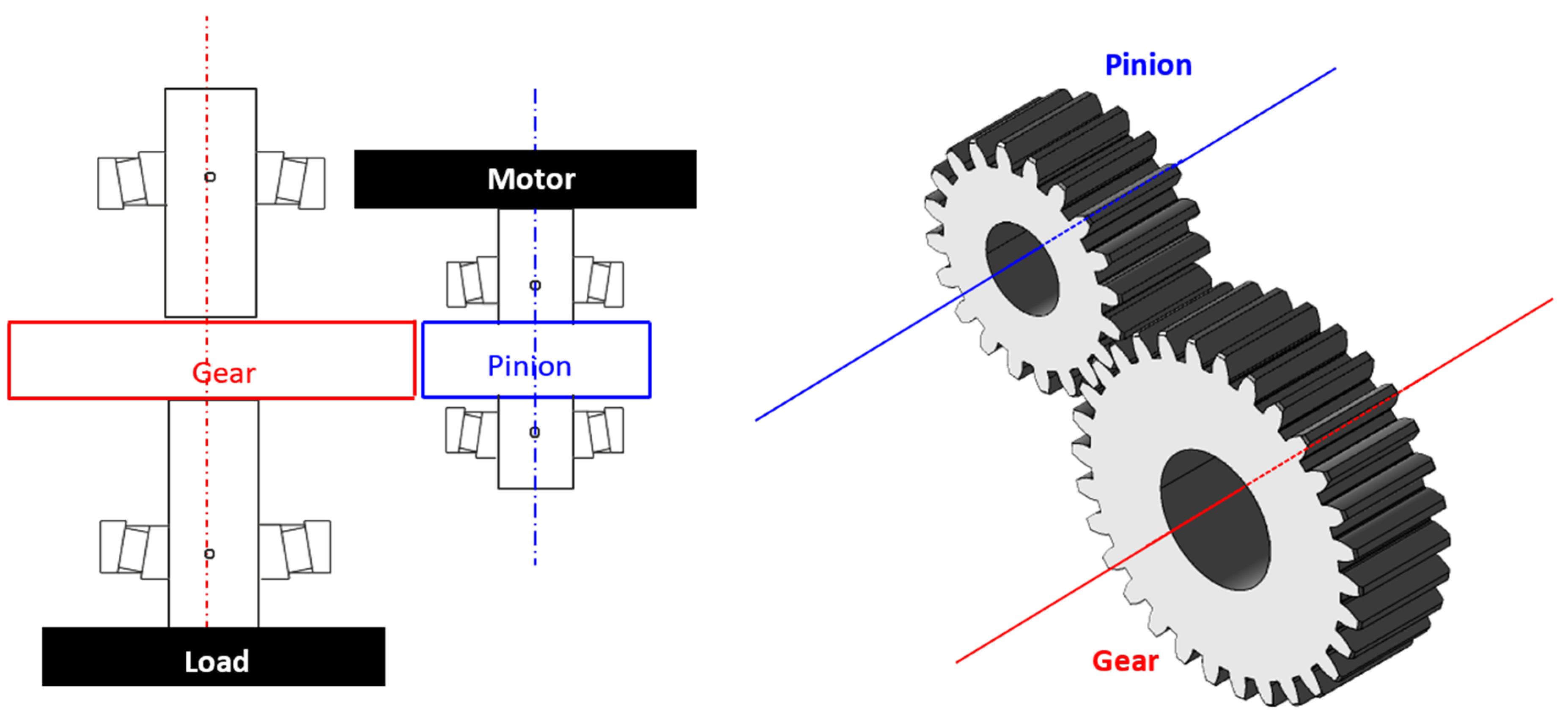
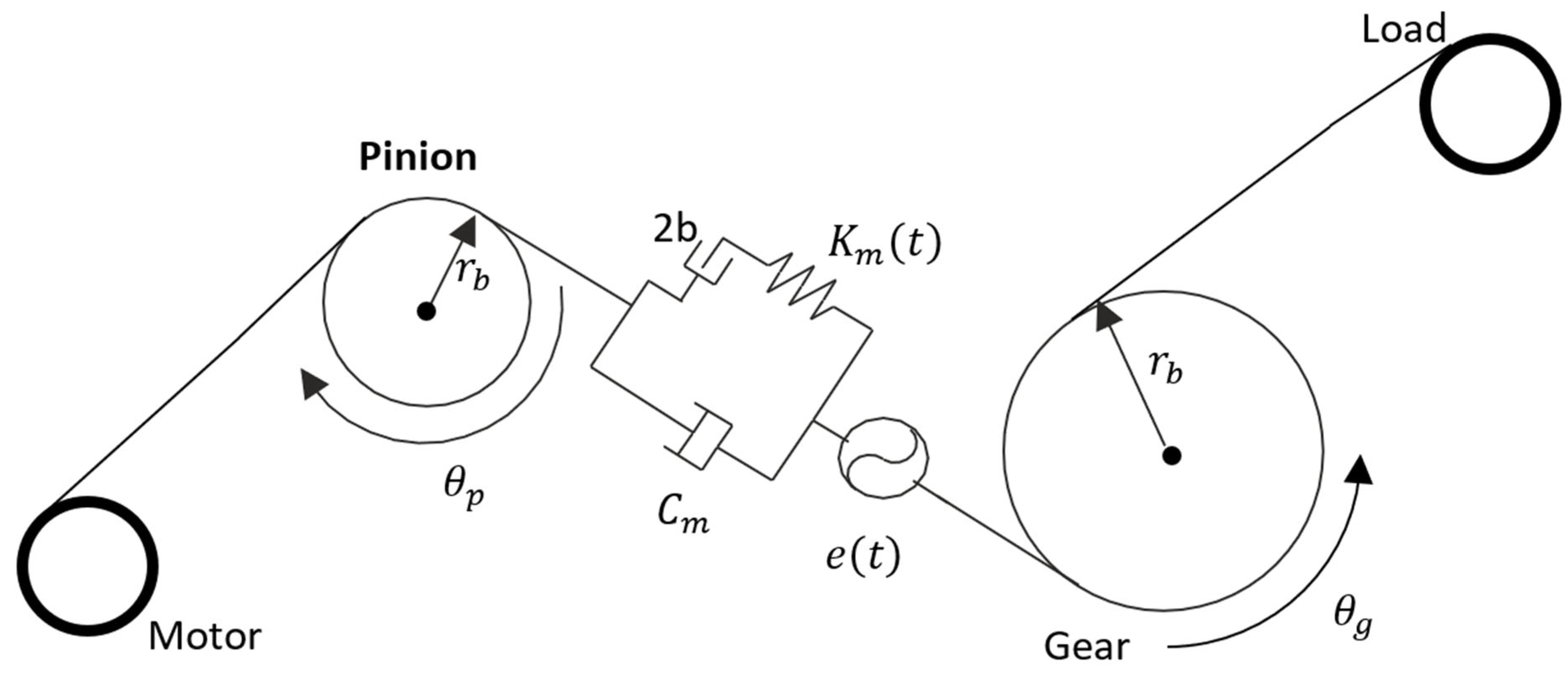
2.1. Gear Pair Dynamical Model

Here, a spur gear pair is considered, see Figure 2. The translational degrees of freedom of both the driver and driven gears are fully constrained, as well as their tilt rotations; only the rotation about the gear axes is allowed. The pinion and gear are rigidly connected to the motor and the load, respectively.
The equations of motion in the “θ” direction for the gear and pinion are:
I g θ ¨ g = r g F z T l
I p θ ¨ p = r p F z + T m
The dynamic transmission error can be defined as:
λ = r p θ p r g θ g + e ( t ) where   e t = j = 1 s e j c o s ( j ω m t t )
e t represents the geometric transmission error (GTE), it is also known as a kinematic transmission error; in spur gears, it refers to the local gaps or deviations between mating teeth, see Figure 3. These errors can result from various factors, including mounting and manufacturing errors, as well as modifications to the teeth profiles. The presence of GTE is important due to the smooth transmission of motion along the line of action between the teeth. The measurement and analysis of GTE are typically carried out through unloaded tooth contact analysis (UTCA): a very low torque is applied to the gear pair, allowing the measurement of the error without significant elastic deformation [24,25,26]. This analysis reflects the rigid body transmission error, which is primarily influenced by geometric factors rather than elastic deformation. The GTE is a critical factor in determining the mesh stiffness of the gear pair, which directly affects the dynamic behavior of the system. Indeed, when one performs the loaded tooth contact analysis and needs to calculate the elastic deformation, the GTE must be removed from the total deformation. When addressing the changes in GTE vs. time, a periodic function expresses its variation as time progresses. A common way to represent the GTE of the system is the Fourier series, where the fundamental frequency is the gear mesh frequency   ω m t = 2 π 60 N p n s ( t ) . Note that ω m t is time-dependent for both coupled and combined models, n s is the input shaft speed (rpm), N p is the number of pinion teeth, s = N 1 1 / 2 is the number of harmonics of the Fourier series.
The dynamic load of the pinion and its component along the line of action F n is calculated as:
F n = K m t f λ e + C m ( λ ˙ e ˙ )
f ( λ e ) = λ + b e , λ e > b 0 , b λ e b λ b e , λ e < b
f λ e   is the backlash function dependent on the linear displacement λ ( t ) , the gap 2 b and the GTE e ( t ) ; whenever λ e   is between b and + b , the contact loss happens (single-sided impact). In the case of forward motion, for λ e > b , the mesh is expected to be in the forward contact (desired situation), while if λ e < b , undesired backside contact happens (double-sided impact) [27,28].
The mesh stiffness of gear pairs varies over time as different teeth come into and out of contact during rotation. This variation is influenced by factors such as gear geometry, material properties, and load distribution. Mesh stiffness variations cause fluctuations in the dynamic mesh force, which, in turn, excite vibrations in the gear system. These vibrations might lead to parametric resonance in the system and may contribute to the premature failure of gear teeth due to fatigue. To calculate the MS of the system (see Figure 4), we need to obtain the elastic deflection of the gear pair. Conducting loaded and unloaded tooth contact analyses, namely, LTCA and UTCA, provides us with loaded static transmission errors, which contain not only elastic deflection but also GTE. Thus, the loaded static transmission errors must be subtracted from GTE obtained from unloaded tooth contact analysis. A periodic function is required to express its variation as time progresses. One commonly employed function to represent the MS of the system is the Fourier series with the fundamental mesh frequency; the Fourier series of the meshing stiffness is given by:
ω m ( t ) = 2 π 60 N p n s ( t ) s = N 1 1 / 2 K m ( t ) = k 0 + j = 1 S a j c o s ( j ω m t t ) + j = 1 S b j s i n ( j ω m t t )
From the pure elastic deformation obtained from the LTCA and UTCA, the meshing stiffness and GTE can be calculated. Therefore, by combining Equations (1)–(4), the final version of the governing equation for a single degree of freedom is written in terms of DTE:
m e q λ ¨ + C m ( λ ˙ e ˙ ) + K m t f λ e = T e q
m e q = r p 2 I p + r g 2 I g 1 , T e q = T m r p
The governing Equation (7) is numerically solved by Simulink ODE23t solver.
Simulink’s graphical environment allows for an intuitive representation of the dynamic interactions among mechanical elements, such as inertia, damping, backlash, and mesh stiffness. Figure 5 illustrates the Simulink model, which corresponds to the mathematical formulation given by Equation (7).

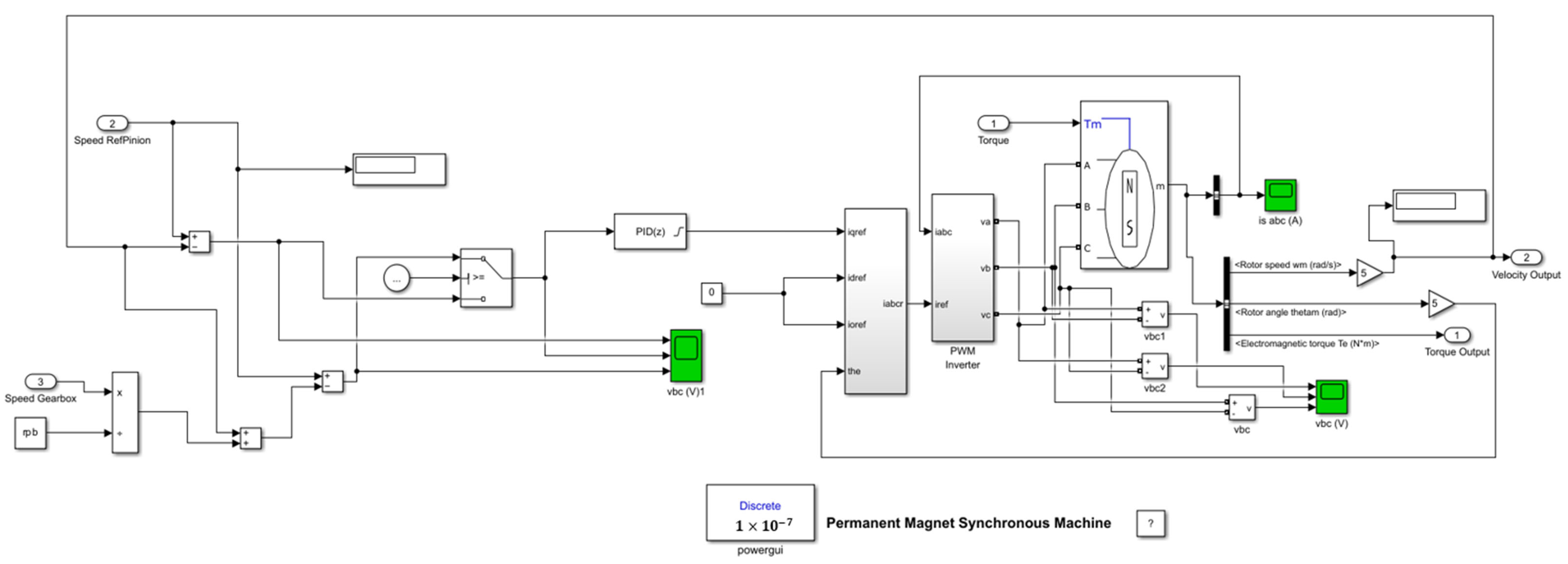
2.2. Model of the Electric Motor

In this study, the electrical drive system is modeled using the PMSM block available in Simulink R2024b [29,30,31]. This built-in block facilitates the simulation of both motor and generator modes, with customizable electrical and mechanical parameters such as stator resistance, inductance, rotor inertia, and torque constant. It supports machine configurations with either sinusoidal or trapezoidal back electromotive force (EMF) profiles and allows for the selection of round or salient-pole rotor types. By accurately reflecting the dynamic behavior of the PMSM under different load conditions and control strategies, this model enables a detailed investigation of electromechanical coupling effects in the system. Figure 6 illustrates the Simulink model for the motor under investigation.
The permanent magnet synchronous machine block, shown in Figure 6, implements a three-phase or a five-phase permanent magnet synchronous machine. The stator windings are connected to an internal neutral point. The three-phase machine can have a sinusoidal or trapezoidal back EMF waveform. The rotor can be a round or salient pole for the sinusoidal machine. The rotor is round when the machine is trapezoidal. Preset models are available for the sinusoidal back EMF machine. The five-phase machine has a sinusoidal back EMF waveform and a round rotor. The permanent magnet synchronous machine block operates in either generator or motor mode. The mode of operation is dictated by the sign of the mechanical torque (positive for motor mode, negative for generator mode). The electrical and mechanical parts of the machine are each represented by a second-order state-space model. The sinusoidal model assumes that the flux established by the permanent magnets in the stator is sinusoidal, which implies that the electromotive forces are sinusoidal.
Equations (9)–(13) are expressed in the rotor reference frame using an extended Park transformation. All quantities in the rotor reference frame are referred to the stator [29,30,31].
d d t i d 1 = ν d 1 L R L i d 1 + L q L p ω m i q 1
d d t i q 1 = ν q 1 L R L i q 1 L d L p ω m i d 1 λ p ω m L
d d t i d 2 = ν d 2 L R L i d 2
d d t i q 2 = ν q 2 L R L i q 2
T e = 2.5 p λ i q 1
In the simulation framework developed in Simulink–MATLAB, the feedback signals are modeled as analog signals. A fixed discrete simulation time step of 0.1 µs (i.e., 1 × 10⁻⁷ s) is used, corresponding to a system bandwidth of approximately 5 MHz. In this work, three different configurations are considered to evaluate the influence of the electrical subsystem on the dynamics of an electromechanical gear transmission system:
(a) Gear-pair system without motor: This configuration is used not only to isolate and evaluate the influence of the electric motor but also to validate the model against experimental data reported by Kahraman and Blankenship [32]. This validation step is essential to ensuring that the proposed Simulink–MATLAB model is both accurate and stable for analyzing the system’s dynamic response.
(b) Gear-pair system combined with motor (no coupling): To incorporate the motor’s effect, one approach is to connect the motor directly to the gear pair without including any feedback from the mechanical subsystem. In this case, only internal motor feedback (i.e., the motor’s output speed) is used for control, as shown in Figure 7a. Although the input speed and torque applied to the gear transmission vary over time, they are not influenced by the gear transmission system, like the fundamental mesh frequency. This is because there is no feedback from the gear system to the motor, so the mechanical dynamics do not affect the motor’s behavior.
(c) Gear-pair system coupled with motor: This configuration more closely reflects real-world conditions, as it includes feedback from the gear transmission. Specifically, the first derivative of the dynamic transmission error, denoted as λ ˙ , is used to influence the motor’s electrical behavior. This coupling introduces a two-way interaction between the mechanical and electrical parts of the system. The feedback from the gear transmission is shown in Figure 7b (blue path).

3. Numerical Results

The nonlinear differential Equation (7) of the gear pair, which includes time-varying parameters, represents a non-smooth and non-autonomous dynamical system, after eliminating the rigid body motion; this equation, combined with the dynamic model of the electric motor, is solved numerically using Simulink–MATLAB. During each simulation, the transient is removed from the total response by cancelling the first 50 periods, obtaining the steady-state response. The total simulation time is set to 3.8 s, which means about 70 rounds of the pinion and 3500 meshing periods. The nominal torque and speed are 340   N m and 115 rad/s, respectively, the fundamental shaft frequency is about 18.3 Hz, and the meshing frequency is 915 Hz, while the natural frequency of the system is 3051 Hz (1.917 × 10⁴ rad/s). The simulation assumes no manufacturing error nor tip or roof reliefs, i.e., e ( t ) = 0 , and the mesh stiffness is simulated using seven harmonics in the Fourier series (the highest harmonic is 21,357 Hz).

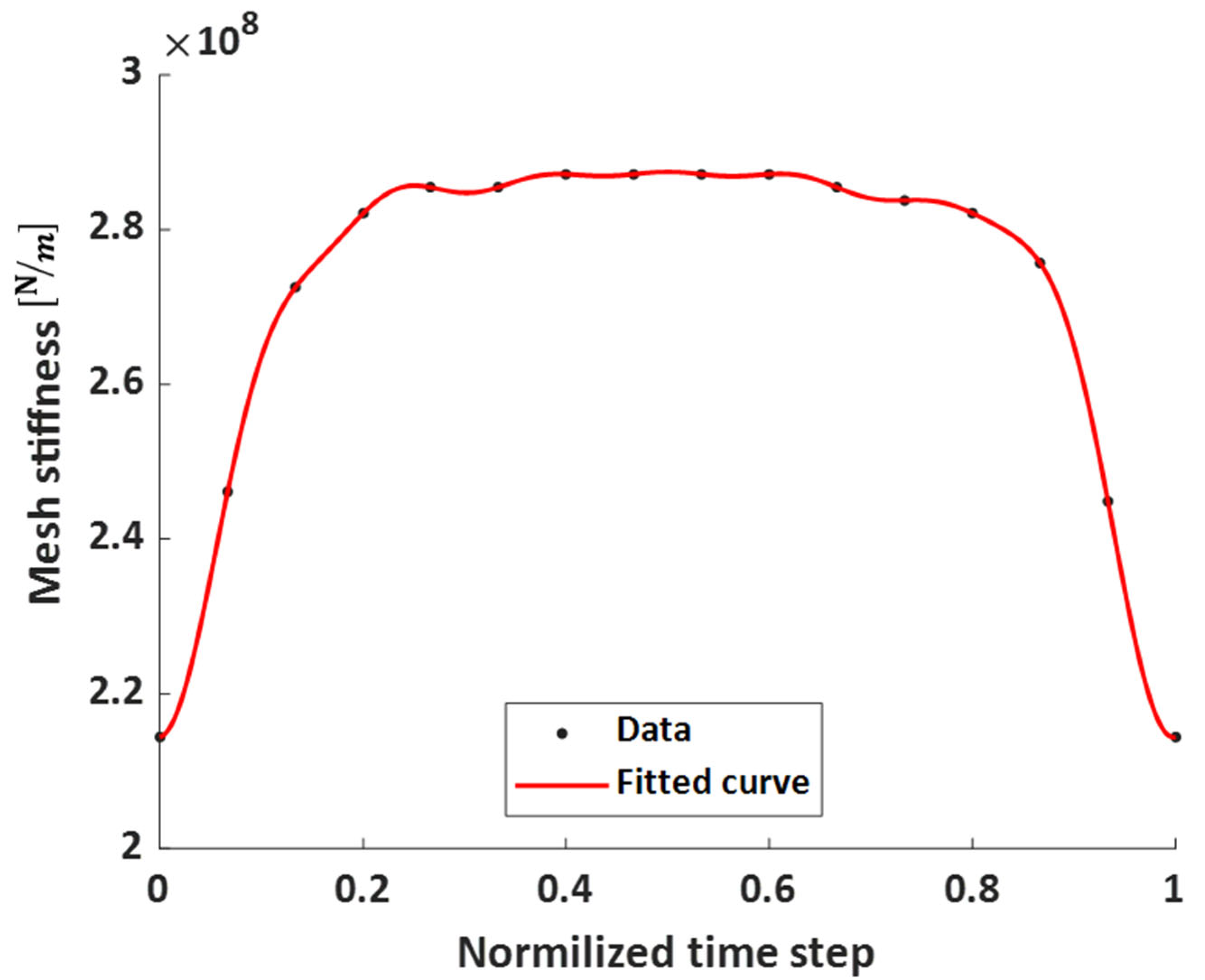
3.1. Validation of the Nonlinear Gear Model

To assess the accuracy of the gear model, a comparison with experimental results is carried out. Kahraman et al. conducted a series of experiments on a setup of a gear pair where the backlash and teeth deflections were not negligible (parametric excitation) and input torque was present. One of these tests focused on a spur gear set with the geometrical and physical parameters presented in Table 1 [32,33]:
The amplitude–frequency diagrams and the root-mean-square (RMS) of the nondimensional dynamic transmission error are used to compare the experimental data [32] with the present numerical simulations. Figure 8 shows a good agreement between the numerical results and the experimental data. Both results, experimental data and Simulink results, clearly capture the key features of nonlinear dynamic behavior, including the softening behavior, primary and super-harmonic resonances, and jump phenomena. The overall shape and the frequency of the resonance are consistent across both cases, confirming the accuracy of the model. Minor discrepancies, such as higher amplitudes in the simulation, may be attributed to idealizations in damping or parameter estimation, but they do not detract from the overall close correspondence. These results confirm that the Simulink model provides a reliable representation of the system’s nonlinear dynamic response.

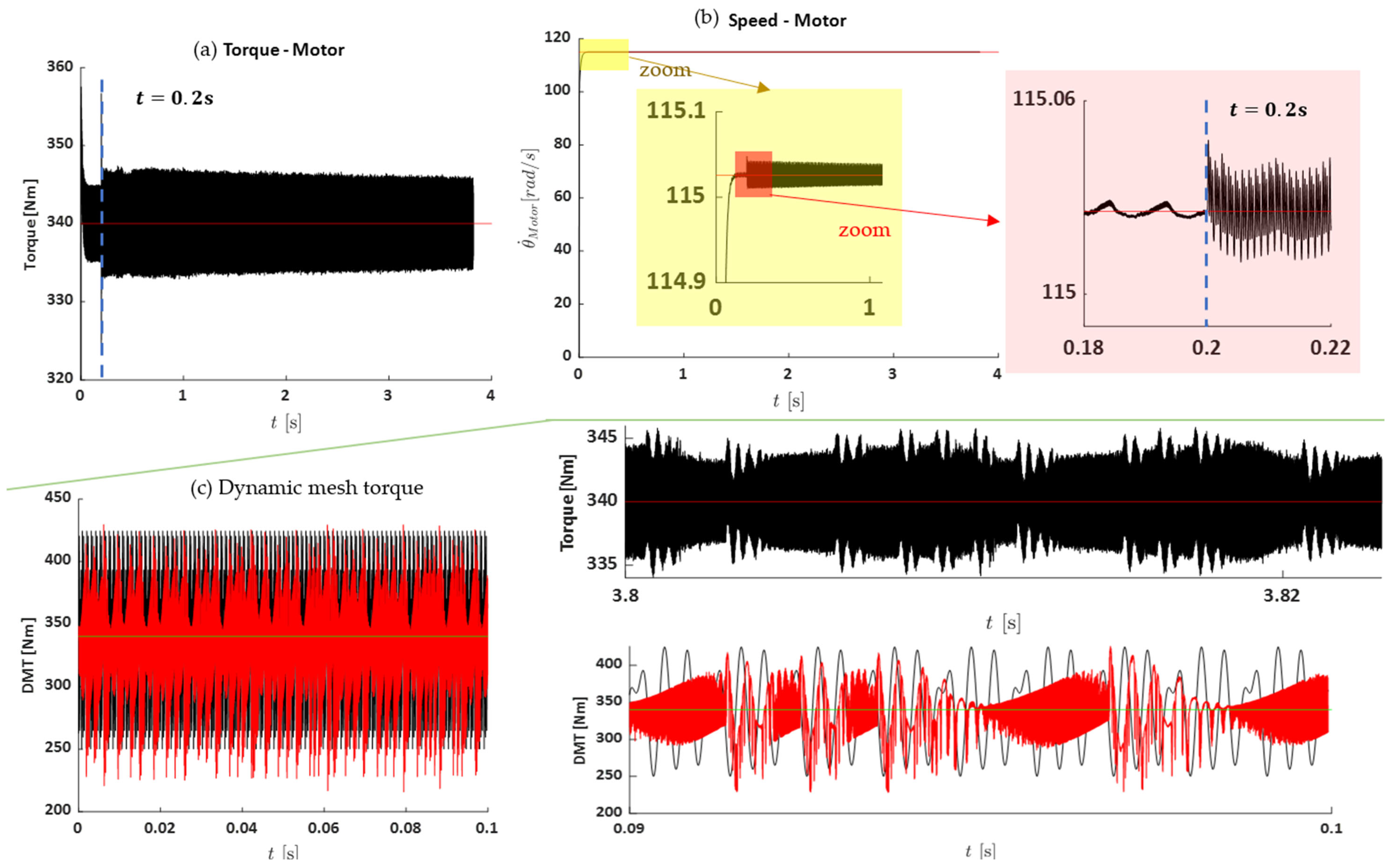
3.2. Dynamic Mesh Torque, Output Torque, and Speed of Motor

To analyze the gear system coupled with the motor, during the simulation, the gear pair is coupled with the motor at t = 0.2   s over a total of 3.8   s . After that instant, the system receives the feedback from the gear pair. As mentioned, the nominal torque is 340 N·m, so as shown in Figure 9a, the output torque of the motor fluctuates around this value with about 14 N·m peak-to-peak oscillation, i.e., 2.06% fluctuation. Regarding the speed of the motor, it stabilizes at the nominal speed of 115 rad/s (18.3 Hz) after 0.2 s, see Figure 9b; after the transient, it continues to fluctuate about the nominal value. The amplitude of fluctuation for both systems, coupled and combined with the motor, is different. Mainly, these characteristics of the coupled system are higher than the combined one.
Regarding the motor speed, it takes some time to reach the nominal value of 115 rad/s (18.3 Hz), as illustrated in Figure 9b. Once stabilized, the speed fluctuates slightly around the nominal level. Notably, the amplitude of both torque and speed fluctuations differs between the coupled and combined systems. These fluctuations are generally more pronounced in the coupled configuration compared to the combined system without gear feedback. The repetitive dynamic load is the main cause of fatigue phenomena such as failure in the tooth root, pitting, and scoring on the tooth surface. Therefore, dynamic mesh torque (DMT) is a key parameter in manufacturing a gear transmission system. The DMT is evaluated by the following formula:
D M T p i n i o n = r p C m λ ˙ e ˙ + K m f λ e
Figure 9c represents the DMT for the two cases: without and coupled with the motor. From the results, it seems the DMT of the coupled system has a higher frequency component than in the case without the motor.

3.3. Dynamic Response of the Systems

The primary parameter used to assess the nonlinear vibrations of the system is the dynamic transmission error (DTE). Figure 10 shows the vibration levels experienced by gears for the three configurations: (i) coupled (red), (ii) combined (blue), and (iii) without the motor (black). Our findings indicate that connecting the electric motor to the gear transmission without incorporating feedback from the mechanical subsystem tends to overestimate the vibration response. This can potentially lead to incorrect system design or inappropriate component selection. The average dynamic transmission error for the three cases is as follows:
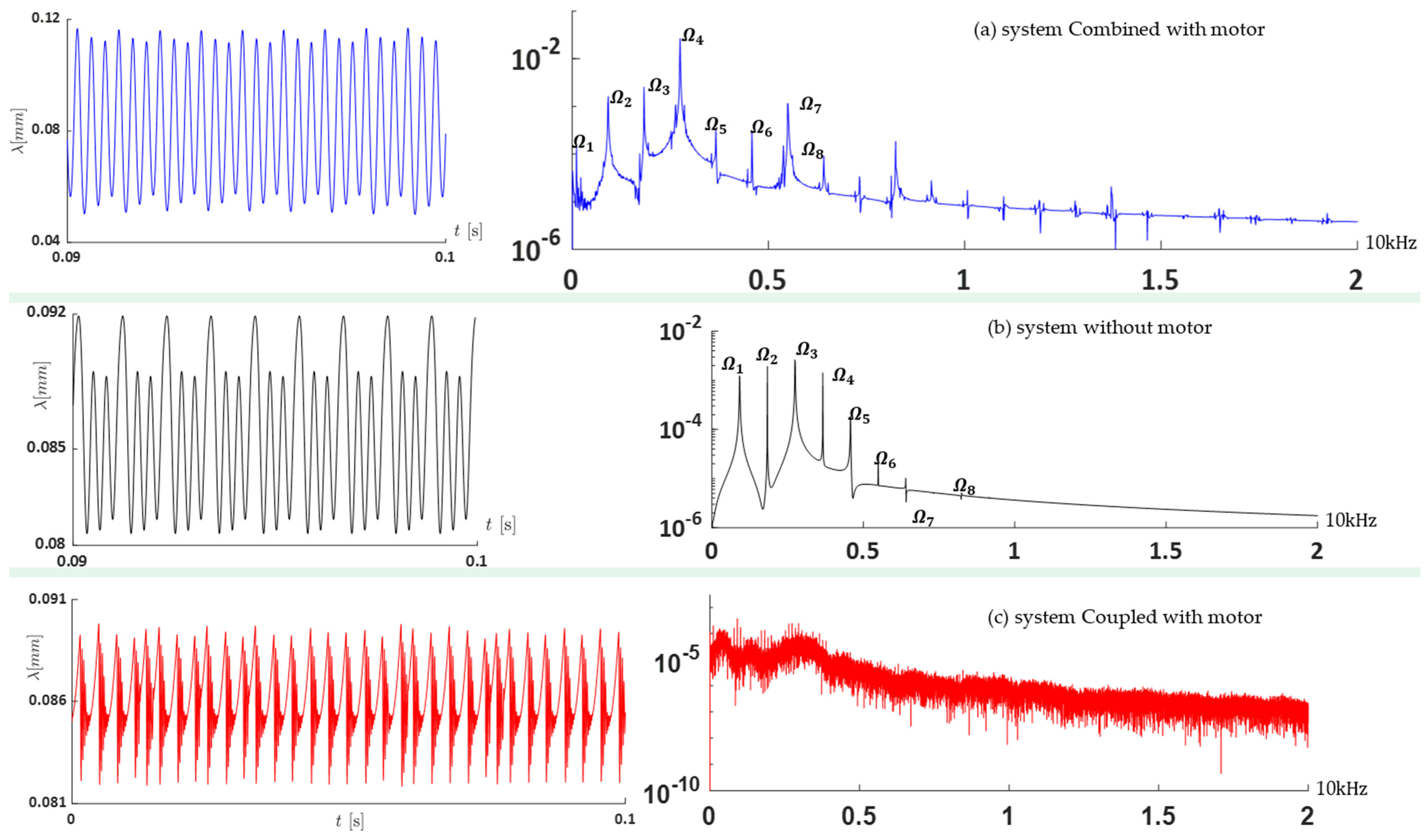
  • System without the motor:
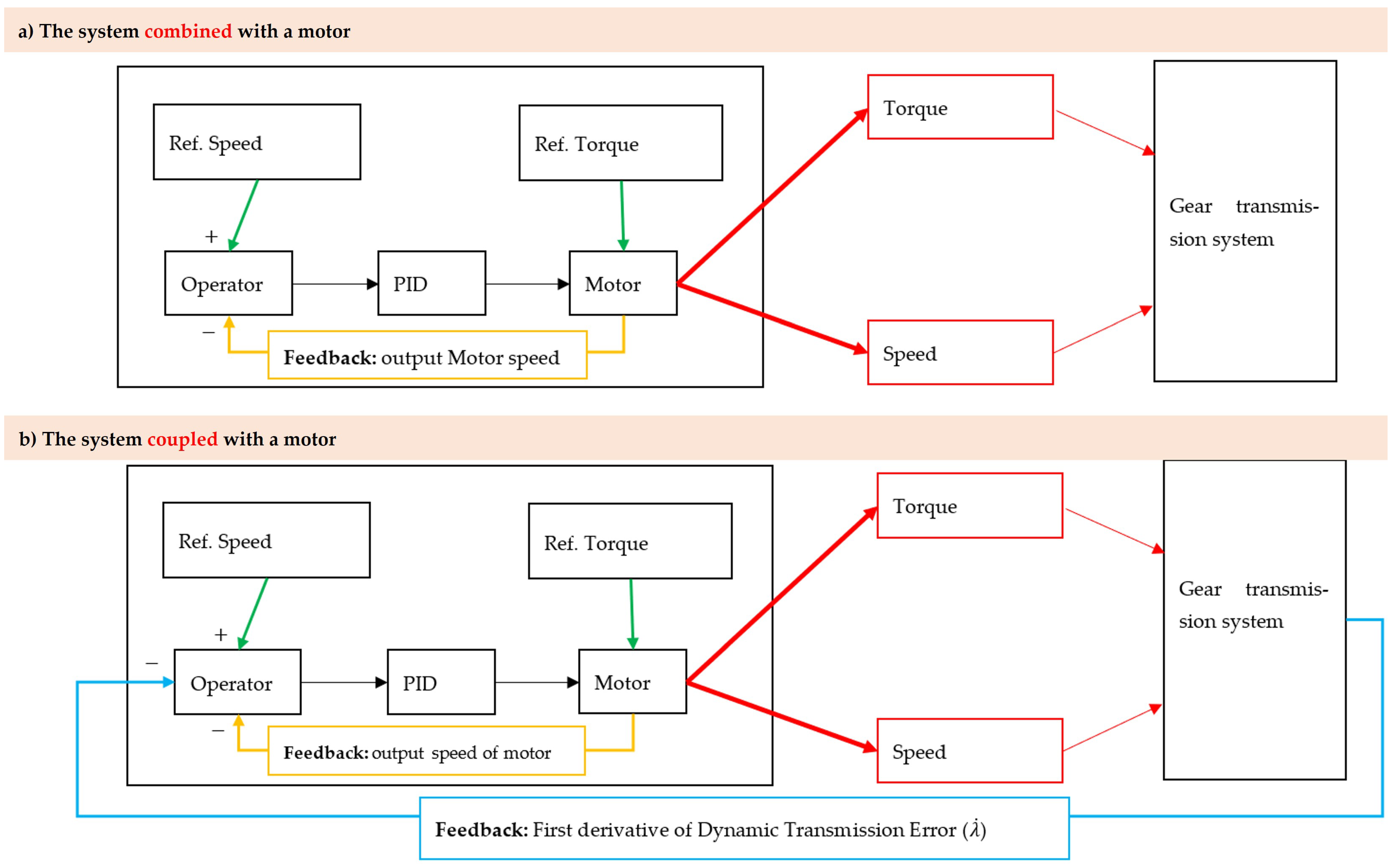
  λ a v e = 0.085   m m
  • Combined system:  λ a v e = 0.082   m m
  • Coupled system:  λ a v e = 0.086   m m

Dynamics of the Systems Under High and Low Levels of Torque

Here, the dynamics of the system under different levels of required torque are analyzed. In this part, two torque levels are considered: low and high, corresponding to half and double the nominal torque, respectively. At low torque (Figure 11), the effect of the motor, when combined with the gear transmission system, is negligible. However, when the motor is coupled with the gear transmission system, the differences become more pronounced. This suggests that the combined system does not fully account for the motor’s effect on the dynamic response. In the second scenario, where the system operates under a high torque level, only two systems are compared: one with the motor coupled and one without, as shown in Figure 12.

3.4. Spectral Analysis

Another insightful analysis of the system dynamics regards the spectrum, computed by using the fast Fourier transform (FFT). The spectra reveal a series of peaks at discrete frequencies, signifying the presence of periodic behavior with minor fluctuations over time (see Figure 13a,b). The strength of this periodic behavior is crucial; pronounced and distinct peaks denote a robust periodicity within the system. Conversely, if periodic behavior is weaker and less prominent, the spectrum will lack distinct peaks (see Figure 13c), resembling a continuous band with some degree of variability. This suggests a weaker or more intricate periodicity within the system. Notably, during the spectral analysis, distinct spikes appear at constant frequency intervals, denoted as Ω, which correspond to beat frequencies, as shown in Table 2. These peaks are integer multiples of the fundamental mesh frequency, indicating that the observed frequencies are harmonically related to the gear meshing process. Consequently, the approximate period of the resulting modulation frequency can be estimated as: T i 1 / Ω i .
Figure 14 shows the spectrum of the motor’s output speed for three different systems. The system without the motor maintains a constant speed of 115 Hz. In contrast, the other two systems, i.e., coupled and combined systems, exhibit fluctuating speeds. The level of speed oscillation is higher in the system coupled with the motor (peak-to-peak is around 0.178 Hz) compared to the system combined with the motor (peak-to-peak is around 0.012 Hz). Interestingly, for the system combined with the motor, the spectrum reveals a single, prominent spike at 110 Hz, which is attributed to the shaft speed (6 × 18.3 Hz), with no other significant spikes observed in the diagram (see Figure 14c, blue). In the system where the motor is coupled, in addition to the spike at 110 Hz, another spike appears at 915 Hz, corresponding to the mesh frequency (50 teeth × 18.3 Hz shaft speed). Furthermore, a sideband at 110 Hz is also present.

4. Conclusions

This study has provided a detailed investigation into the dynamic interactions between a permanent magnet synchronous machine and a nonlinear spur gear transmission system. By analyzing three distinct models—namely, a standalone gear system, a combined system without dynamic feedback from the gear transmission system, and a fully coupled electromechanical system—we have demonstrated the influence of motor–gear coupling on system dynamics. The numerical simulations, validated against experimental data, confirm the reliability and accuracy of the proposed Simulink–MATLAB model in capturing the nonlinear behavior of gear transmissions. Importantly, the inclusion of mechanical feedback via the derivative of the dynamic transmission error significantly alters both the motor output characteristics and the overall vibrational response of the system. This coupled feedback loop introduces higher-frequency components in the dynamic mesh torque and amplifies oscillations in both torque and speed, particularly under nominal and high-load conditions.
Our findings highlight the limitations of traditional modeling approaches that neglect electromechanical feedback as they tend to underestimate or misrepresent dynamical behavior. Moreover, the spectral analysis reveals that dynamic coupling introduces harmonics and sidebands in the output motor speed, associated with gear meshing frequencies, which are absent in combined configurations. These insights are essential for the accurate design, control, and durability assessment of advanced electromechanical powertrains. Ignoring the bidirectional interaction between motor control and gear dynamics may result in suboptimal system performance or premature failure due to unaccounted fatigue mechanisms.

Supplementary Materials

The following supporting information, the Simulink Model, used to conduct this analysis, can be downloaded from the following link: https://www.mdpi.com/article/10.3390/vibration8030034/s1.

Author Contributions

Conceptualization, A.Z., F.P. and M.M.; methodology, A.Z., F.P. and M.M.; software, A.Z. and M.M.; validation, A.Z., F.P. and M.M.; formal analysis, A.Z., F.P. and M.M.; investigation, A.Z., F.P. and M.M.; resources, A.Z. and F.P.; data curation, A.Z. and M.M.; writing—original draft preparation, A.Z. and M.M.; writing—review and editing, A.Z., F.P. and M.M.; visualization, A.Z., F.P. and M.M.; supervision, A.Z. and F.P.; project administration, A.Z. and F.P.; funding acquisition, A.Z. and F.P. All authors have read and agreed to the published version of the manuscript.

Funding

The financial support was provided by Region Emilia Romagna PR FESR 2021–2027 Action 1.1.2, titled “THEORETIC”, C.U.P.: E67G22000610001.

Data Availability Statement

The original data presented in the study are openly available in Mendeley data repository at Supplementary Materials https://doi.org/10.17632/5rjgkcyp7g.1.

Conflicts of Interest

The authors declare no conflicts of interest.

List of Symbols

LArmature inductance
RResistance of the stator windings
Lq, Ldq-axis and d-axis inductances
T e Electromagnetic torque
iq1, id1q1-axis and d1-axis currents
vq1, vd1q1-axis and d1-axis voltages
iq2, id2q2-axis and d2-axis currents
vq2, vd2q2-axis and d2-axis voltages
ωmAngular velocity of the rotor
λAmplitude of the flux induced by the permanent magnets of the rotor in the stator phases
pNumber of pole pairs
I g , I p Momentum inertia of the gear and pinion
r g , r p Pitch radius of gear and pinion, respectively
θ p , θ g Rotational degree of freedom for the pinion and gear
T m Input torque
T l Output torque
λ Dynamic transmission error
e Geometric transmission error
K m t Mesh stiffness
f λ e Backlash function
n s ( t ) Input speed
N p Teeth number of pinion
m e q Equivalent mass
T e q Equivalent torque
C m Damping

References

  1. Qian, J.; Ji, C.; Pan, N.; Wu, J. Improved Sliding Mode Control for Permanent Magnet Synchronous Motor Speed Regulation System. Appl. Sci. 2018, 8, 2491. [Google Scholar] [CrossRef]
  2. Xu, D.; Wang, T.; Liu, J.; Wei, H. Research on Optimal-Torque Control Method of Permanent Magnet Synchronous Motor. In Proceedings of the 2008 3rd IEEE Conference on Industrial Electronics and Applications, Singapore, 3–5 June 2008; pp. 1229–1233. Available online: https://ieeexplore.ieee.org/document/4582715 (accessed on 25 April 2025).
  3. Zhang, G.; Yu, W.; Hua, W.; Cao, R.; Qiu, H.; Guo, A. The Design and Optimization of an Interior, Permanent Magnet Synchronous Machine Applied in an Electric Traction Vehicle Requiring a Low Torque Ripple. Appl. Sci. 2019, 9, 3634. [Google Scholar] [CrossRef]
  4. Sreejeth, M.; Singh, M.; Kumar, P. Particle swarm optimisation in efficiency improvement of vector controlled surface mounted permanent magnet synchronous motor drive. IET Power Electron. 2015, 8, 760–769. [Google Scholar] [CrossRef]
  5. Wang, S.C.; Nien, Y.C.; Huang, S.M. Multi-Objective Optimization Design and Analysis of V-Shape Permanent Magnet Synchronous Motor. Energies 2022, 15, 3496. [Google Scholar] [CrossRef]
  6. Sun, X.; Hu, C.; Lei, G.; Guo, Y.; Zhu, J. State Feedback Control for a PM Hub Motor Based on Gray Wolf Optimization Algorithm. IEEE Trans. Power Electron. 2020, 35, 1136–1146. [Google Scholar] [CrossRef]
  7. Shang, D.X.; Liu, Y.C.; Sun, F.J.; Zhang, H.Y. Study on DTC-SVM of PMSM Based on Propeller Load Characteristic. In Proceedings of the 2008 7th World Congress on Intelligent Control and Automation, Chongqing, China, 25–27 June 2008; pp. 6445–6449. Available online: https://ieeexplore.ieee.org/document/4593905 (accessed on 25 April 2025).
  8. Molaie, M.; Deylaghian, S.; Iarriccio, G.; Samani, F.S.; Zippo, A.; Pellicano, F. Planet Load-Sharing and Phasing. Machines 2022, 10, 634. [Google Scholar] [CrossRef]
  9. Jędryczka, C.; Danielczyk, D.; Szeląg, W. Torque Ripple Minimization of the Permanent Magnet Synchronous Machine by Modulation of the Phase Currents. Sensors 2020, 20, 2406. [Google Scholar] [CrossRef]
  10. Dai, Y.; Lee, H.J. Torque Ripple and Electromagnetic Vibration Suppression of Fractional Slot Distributed Winding ISG Motors by Rotor Notching and Skewing. Energies 2024, 17, 4964. [Google Scholar] [CrossRef]
  11. Hu, J.; Peng, T.; Jia, M.; Yang, Y.; Guan, Y. Study on Electromechanical Coupling Characteristics of an Integrated Electric Drive System for Electric Vehicle. IEEE Access 2019, 7, 166493–166508. [Google Scholar] [CrossRef]
  12. Jiang, S.; Li, W.; Wang, Y.; Yang, X.; Xu, S. Study on electromechanical coupling torsional resonance characteristics of gear system driven by PMSM: A case on shearer semi-direct drive cutting transmission system. Nonlinear Dyn. 2021, 104, 1205–1225. [Google Scholar] [CrossRef]
  13. Ge, S.; Hou, S.; Yao, M. Electromechanical Coupling Dynamic Characteristics of the Dual-Motor Electric Drive System of Hybrid Electric Vehicles. Energies 2023, 16, 3190. [Google Scholar] [CrossRef]
  14. Guo, D.; Huang, D.; Ge, S.; Wang, Y.; Shen, Q. Vibration characteristics of electric drive system considering rotor-step skewing. Proc. Inst. Mech. Eng. Part D 2024, 238, 4142–4153. [Google Scholar] [CrossRef]
  15. Xie, Y.; Lim, K.; Liu, H.; Zhan, Z.; Ren, X.; Li, X.; Zhou, R.; Gao, P.; Xiang, C. Modelling of electromechanical coupling dynamics for high-speed EHT system used in HEV and characteristics analysis. Appl. Math. Model. 2024, 136, 115614. [Google Scholar] [CrossRef]
  16. Liu, Y.; Wang, Z.; Yang, J.; Zhang, Y.; Pu, W. Electromechanical dynamic behavior of gear systems caused by transient mixed lubrication of rubbing surface. Tribol. Int. 2025, 204, 110459. [Google Scholar] [CrossRef]
  17. Dou, J.; Li, Z.; Yao, H.; Ding, M.; Wei, G. Torsional vibration suppression and electromechanical coupling characteristics of electric drive system considering misalignment. Appl. Math. Mech. 2024, 45, 1987–2010. [Google Scholar] [CrossRef]
  18. Li, H.; Guo, Y.; Xu, Q. PMSM Torque Ripple Suppression Method Based on SMA-Optimized ILC. Sensors 2023, 23, 9317. [Google Scholar] [CrossRef] [PubMed]
  19. Müller, K.; Wanke, A.; Burkhardt, Y.; Gersem, H.D. Evaluation of Torque Ripple and Tooth Forces of a Skewed PMSM by 2D and 3D FE Simulations. arXiv 2025. Available online: http://arxiv.org/abs/2503.16279 (accessed on 30 April 2025).
  20. Bai, W.; Qin, D.; Wang, Y.; Lim, T.C. Dynamic characteristic of electromechanical coupling effects in motor-gear system. J. Sound Vib. 2018, 423, 50–64. [Google Scholar] [CrossRef]
  21. Yi, Y.; Qin, D.; Liu, C. Investigation of electromechanical coupling vibration characteristics of an electric drive multistage gear system. Mech. Mach. Theory 2018, 121, 446–459. [Google Scholar] [CrossRef]
  22. Ge, S.; Qiu, L.; Zhang, Z.; Wang, H.; Hu, M. Electromechanical coupling dynamic characteristics of electric drive system for electric vehicle. Nonlinear Dyn. 2024, 112, 6101–6136. [Google Scholar] [CrossRef]
  23. Chen, X.; Yuan, S.; Peng, Z. Nonlinear vibration for PMSM used in HEV considering mechanical and magnetic coupling effects. Nonlinear Dyn. 2015, 80, 541–552. [Google Scholar] [CrossRef]
  24. Molaie, M.; Samani, F.S.; Zippo, A.; Pellicano, F. Spiral Bevel Gears: Nonlinear dynamic model based on accurate static stiffness evaluation. J. Sound Vib. 2023, 544, 117395. [Google Scholar] [CrossRef]
  25. Molaie, M.; Samani, F.S.; Zippo, A.; Iarriccio, G.; Pellicano, F. Spiral bevel gears: Bifurcation and chaos analyses of pure torsional system. Chaos Solitons Fractals 2023, 177, 114179. [Google Scholar] [CrossRef]
  26. Anuradha, G.; Sagi, R.P.; Shakya, P.; Sekhar, A.S. Influence of Geometric Parameters on the Dynamic Performance of Spiral Bevel Gear. J. Vib. Eng. Technol. 2024, 12, 9097–9111. [Google Scholar] [CrossRef]
  27. Molaie, M.; Zippo, A.; Pellicano, F. Chaotic dynamics of spiral bevel gears. Int. J. Non-Linear Mech. 2025, 175, 105098. [Google Scholar] [CrossRef]
  28. Molaie, M.; Samani, F.S.; Pellicano, F. Spiral Bevel Gears Nonlinear Vibration Having Radial and Axial Misalignments Effects. Vibration 2021, 4, 666–678. [Google Scholar] [CrossRef]
  29. Grenier, D.; Dessaint, L.A.; Akhrif, O.; Bonnassieux, Y.; Le Pioufle, B. Experimental nonlinear torque control of a permanent-magnet synchronous motor using saliency. IEEE Trans. Ind. Electron. 1997, 44, 680–687. [Google Scholar] [CrossRef]
  30. Toliyat, H.A. Analysis and Simulation of Multi-Phase Variable Speed Induction Motor Drives Under Asymmetrical Connections. In Proceedings of the Applied Power Electronics Conference APEC ’96, San Jose, CA, USA, 3–7 March 1996; Volume 2, pp. 586–592. Available online: https://ieeexplore.ieee.org/abstract/document/500500 (accessed on 25 April 2025).
  31. Baudart, F.; Labrique, F.; Matagne, E.; Telteu, D.; Alexandre, P. Control Under Normal and Fault Tolerant Operation of Multiphase SMPM Synchronous Machines with Mechanically and Magnetically Decoupled Phases. In Proceedings of the 2009 International Conference on Power Engineering, Energy and Electrical Drives, Lisbon, Portugal, 18–20 March 2009; pp. 461–466. Available online: https://ieeexplore.ieee.org/abstract/document/4915200 (accessed on 25 April 2025).
  32. Kahraman, A.; Blankenship, G.W. Experiments on Nonlinear Dynamic Behavior of an Oscillator with Clearance and Periodically Time-Varying Parameters. J. Appl. Mech. 1997, 64, 217–226. [Google Scholar] [CrossRef]
  33. Bonori, G.; Pellicano, F. Non-smooth dynamics of spur gears with manufacturing errors. J. Sound Vib. 2007, 306, 271–283. [Google Scholar] [CrossRef]
  34. Blankenship, G.W.; Kahraman, A. Steady state forced response of a mechanical oscillator with combined parametric excitation and clearance type non-linearity. J. Sound Vib. 1995, 185, 743–765. [Google Scholar] [CrossRef]
Figure 1. A model for an electromechanical gear transmission system.
Vibration 08 00034 g001
Figure 2. A dynamical model of a spur gear pair with a rigid connection to the motor and load.
Vibration 08 00034 g002
Figure 3. Geometric transmission error due to tooth profile imperfections.
Vibration 08 00034 g003
Figure 4. Mesh stiffness of the spur gear pair.
Vibration 08 00034 g004
Figure 5. The Simulink model of the gear pair transmission system.
Vibration 08 00034 g005
Figure 6. The Simulink model of an electric motor.
Vibration 08 00034 g006
Figure 7. The proposed model for considering the effect of the motor.
Vibration 08 00034 g007
Figure 8. A comparison of the simulated model in Simulink and experimental data.
Vibration 08 00034 g008
Figure 9. Output results of the motor: (a) torque, (b) speed, and (c) dynamic mesh torque for two cases: coupled with the motor; ● without the motor.
Vibration 08 00034 g009
Figure 10. Dynamic transmission error, i.e., λ , for T n = 340   N · m . ( red) Coupled with the motor; (● black) without the motor; ( blue) combined with the motor.
Vibration 08 00034 g010
Figure 11. Dynamic transmission error, i.e., λ , for low-level torque: T = 0.5 × T n . ( red) Coupled with the motor; (● black) without the motor; ( blue) combined with the motor.
Vibration 08 00034 g011
Figure 12. Dynamic transmission error, λ , for high-level torque: T = 2 × T n . ( red) Coupled with the motor; (● black) without the motor.
Vibration 08 00034 g012
Figure 13. FFT spectrum analysis on dynamic transmission error: coupled with the motor; ● without the motor; combined with the motor.
Vibration 08 00034 g013
Figure 14. FFT spectrum analysis on output speed of the motor: coupled with the motor; combined with the motor.
Vibration 08 00034 g014
Table 1. Pinion and gear data.
Tooth ParametersPinionGear
No. of teeth5050
Module [mm]33
Pressure angle [Deg]2020
Base diameter [mm]140.95140.95
Tooth thickness at pitch diameter [mm]4.644.64
Outer diameter [mm]156156
Root diameter [mm]140.68140.68
Face width [mm]2020
Inertia [kg m2] 0.00740.0074
Backlash [mm] 0.1447
Center distance [mm]150
Damping ratio [34]0.01
Table 2. FFT spectrum data at ω m = 115   r a d s = 18.3   H z .
i Combined Without Coupled
Ω i
[Hz]
Ω i ω m Ω i
[Hz]
Ω i ω m Ω i
[Hz]
Ω i ω m
11106920501106
291050183010037020
31830100274115091050
4275015036612002961162
5366020045722503221176
645802505492500
755003006403550
864103508244450
Disclaimer/Publisher’s Note: The statements, opinions and data contained in all publications are solely those of the individual author(s) and contributor(s) and not of MDPI and/or the editor(s). MDPI and/or the editor(s) disclaim responsibility for any injury to people or property resulting from any ideas, methods, instructions or products referred to in the content.

