Abstract
This paper addresses deficiencies in existing spray carts and suspended sprayers regarding operational scenarios, spray coverage, versatility, and wall film thickness adjustment by designing a rail-mounted rotating nozzle application robot. Static analysis of the robot frame verifies compliance with strength and stiffness requirements. Motor torque calculations ensure stable and reliable nozzle rotation. Geometric modeling derives optimal link parameters for automated nozzle angle control. ANSYS Fluent simulations characterize static spray coverage, analyzing quantitative relationships between nozzle height, angle, and spray distance. SolidWorks Motion establishes a coupled model of nozzle rotation and cart translation to obtain spray trajectories under varying speeds. Coupled Fluent simulations further evaluate wall film thickness distribution patterns under dynamic spraying conditions. The findings provide a theoretical foundation and technical reference for structural optimization and precise spraying control in greenhouse spraying robot systems.
1. Introduction
Greenhouse cultivation is a primary form of facility agriculture in China, widely used for high-value crops such as fruits, vegetables, and flowers [1]. Unlike outdoor environments, the enclosed nature and high humidity of greenhouses increase susceptibility to pests and diseases, directly impacting yield and quality. Consequently, efficient, precise, and environmentally friendly plant protection is crucial for ensuring stable production and quality improvement [2]. Green development further necessitates pesticide reduction and residue control, requiring application methods that balance precision and ecology. Among greenhouse types, ground-planted dense planting is prevalent due to low input costs and strong adaptability [3]. However, narrow inter-row passages and structural constraints pose significant challenges for conventional pesticide application methods. While early manual sprayers played an important role, they suffer from low efficiency, high labor intensity, insufficient spray utilization and deposition uniformity, and high operator exposure risk, failing to meet the modern facility agriculture demands for “high efficiency, precision, and low residue” [4]. Consequently, spatially adaptable, precisely controlled, and high-coverage-efficiency greenhouse pesticide application robots are urgently needed.
For greenhouses with larger row spacing, researchers have proposed various inter-row operation robots. Abioye et al. integrated deep learning for disease identification and variable-rate control, improving targeting precision [5]. Fu et al. developed an improved self-propelled precision sprayer, enhancing uniformity and stability through frame identification and optimization [6]. Sammons et al. proposed a rail-walking row spraying platform utilizing riser diverter sprinklers for crops on both sides. These solutions perform well in elevated or spaced layouts, offering good maneuverability and accessibility. However, in dense ground-planting scenarios, restricted inter-row passages lead to spraying blind spots, nozzle interference with plants/structures, and inconsistent coverage (repeated or missed spraying) [7]. Thus, effective pesticide application in dense planting spaces requires alternative approaches and novel mechanisms.
To overcome inter-row constraints, some studies shifted the working position above the plants. Li et al. proposed a CSG (Chinese solar greenhouse) double-track suspension inter-row sprayer with fixed-arm and lifting spraying modes, moving east–west for parallel spraying [8]. However, implementation challenges arise from shed column constraints, stability and maintainability of long cantilevers, and limited adaptability to light long-span greenhouses. Lin et al. designed a single-hanging rail autonomous air-assisted sprayer, adjusting spraying distance via dual centrifugal fan power for up/down processing [9]. Nevertheless, insufficient deposition at the bottom and edges persisted. Zhang et al. constructed an integrated solar greenhouse air supply and fine mist system, coupling air duct supply with air-assisted atomization [10]. Measurements showed improved droplet deposition uniformity under optimal parameters (e.g., 10 m/s wind speed, 135° direction angle). However, fixed ceiling sprinklers face limitations in cleaning, disassembly, anti-blocking, and parameter adaptation, struggling to maintain stable performance across diverse greenhouse types, crops, and growth stages.
In summary, the application operation of ground-planted dense greenhouses faces multiple challenges: on the one hand, due to the narrow spacing between crops and the limited space between rows, it is difficult for traditional walking robots to achieve effective passage and uniform spraying, which can easily lead to insufficient blind spots and coverage consistency [11]; On the other hand, different greenhouse structure types (e.g., central columns vs. light long-span) limit the layout and maintenance of row booms and fixed sprinklers, reducing the adaptability and stability of the system [12]. At the same time, there is a lack of systematic research on the effects of spray parameters and airflow assistance on droplet deposition uniformity, coverage depth and droplet fallback behavior in dynamic motion (e.g., robot translation and nozzle rotation or pitch adjustment at the same time) [13]. In addition, the geometric design and dimensional parameters of the current nozzle angle adjustment mechanism often rely on experience, and there is a lack of generalizable optimization models and kinematic analysis methods, which is difficult to support automatic adjustment and structural reuse in a variety of working environments [14].
To address these problems, this paper proposes a hanging rail spray robot featuring rotational motion and adjustable nozzle angles. The work and contributions include: (1) Structural design and static analysis of the robot frame and hanging mechanism, verifying strength and stiffness meet greenhouse operational demands [15]; (2) Motor torque calculation and selection for the rotating nozzle drive chain, ensuring stable and reliable rotation [16]; (3) Development of a geometric-kinematic model for nozzle angle adjustment, deriving optimal nozzle position and link length to provide a theoretical basis for automatic control; (4) Construction of a multi-domain simulation system: ANSYS Fluent characterizes static spray coverage (relationships between height, angle, and maximum spray distance); SolidWorks Motion obtains coupled rotation-translation trajectories; and coupled Fluent simulations evaluate dynamic wall film thickness distribution under varying rotational speeds, translational speeds, and pump pressures [17]. This study aims to provide a novel application approach with strong structural accessibility, adjustable parameters, and verifiable coverage for dense-planting greenhouses, alongside a reusable framework for precise spraying control and engineering optimization. Unlike prior dynamic spraying studies—such as Chen’s electrostatic rotary bell model for trajectory optimization [18], Xu’s wall-climbing robotic painter for ship coatings [19], and Wu’s hybrid robot focusing on motion accuracy [20], which all simplify spray patterns as circular/annular areas—this work employs SolidWorks and ANSYS Fluent to analyze deposition gradients along curved paths. This approach captures authentic film thickness distributions in arc spraying, providing more realistic simulations and technical references.
Key innovations distinguish this greenhouse sprayer from conventional linear boom systems:
- Replacement of linear nozzle arrays with a curved configuration, applying inverse transformation methodology;
- Implementation of position-adjustable nozzles enhancing environmental adaptability;
- Height and atomization adjustability enabling multidimensional film thickness control.
These advances significantly improve versatility: angular adjustments accommodate varying greenhouse widths, while off-center track installation avoids mid-structure collisions. Unlike linear booms requiring dual-pass spraying around obstacles, this rotary system completes full
2. Materials and Methods
The hanging rail spraying robot comprises a hanging rail travelling mechanism and a rotary spraying mechanism. The travelling mechanism provides propulsion along the rail, while the spraying mechanism performs the rotational spraying function. Coordinated movement enables combined translation and rotation [21].
2.1. Hanging Rail Travelling Mechanism
The hanging rail travelling mechanism lifts and moves the spraying assembly, which includes components like the pressure pump, power supply, chemical tank, and rotary spray nozzle. As spraying requires stable, low-speed movement under load, a low-speed, high-torque mechanism was needed. The JY-01 single-wheel transporter (Figure 1) was bought, offering a load capacity of 250 kg and a maximum speed of 45 m/min (equivalent to a slow walking pace). Remote control enables forward and reverse movement. For the track section, purchase C-type tracks (Figure 2), chosen for simple installation, good sliding performance, affordability, and high strength.
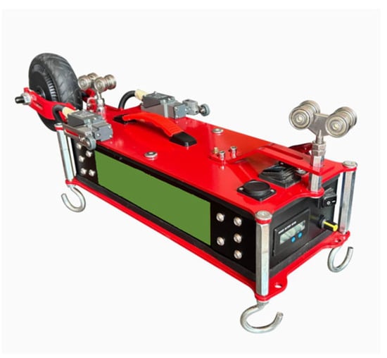
Figure 1.
Single-wheel transporter.
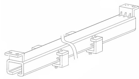
Figure 2.
C-shaped hanging rail.
2.2. Spraying Execution Assembly
The spraying assembly includes the chemical tank, pressure pump, power supply, and rotary spray nozzle. A hook-mounted outer frame houses these components. The dimensions of these externally purchased appliances are shown in Table 1.

Table 1.
Purchased Components Information Sheet.
To minimize weight while accommodating all devices, the outer frame dimensions were set to 500 mm × 500 mm × 480 mm, constructed from 6063-O aluminum [22]. Four small casters facilitate movement and transportation (Figure 3).
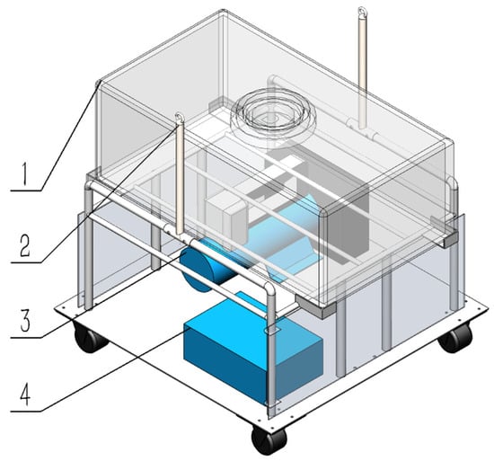
Figure 3.
Outer frame assembly. 1—Water Tank, 2—Hook, 3—Plunger Pump, 4—Lithium Battery.
The rotary spray nozzle assembly is mounted on a track at the bottom of the outer frame. Its position is adjustable by sliding the fixing bolt within the track. The 3D structure of the self-designed rotating spray actuator is shown in Figure 4. The marked parts are purchased components; the remaining parts and the overall structure are independently designed in this work. Rotational power is provided by a Small electric motor (maximum speed: 222 RPM (Revolutions Per Minute), adjustable maximum torque: ). Power is transmitted via a timing belt to a high-pressure rotary joint. Only the joint’s end rotates, while the rear section remains stationary, driving the lower rotating nozzle. As synchronous pulleys are used, the nozzle speed matches the motor speed.
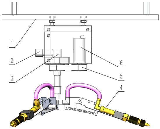
Figure 4.
Three-dimensional view of rotating spray nozzle assembly. 1—Track; 2—Water Inlet; 3—High-pressure Rotary Joint; 4—Nozzle; 5—Timing Belt Drive; 6—Small electric motor (speed adjustable).
2.3. Critical Component Simulation and Structural-Functional Design
This section details the analyses performed: according to the top-down sequence of the rotating spray system robot, static frame analysis to verify mechanical integrity, motor torque calculation to ensure reliable rotation, kinematic derivation of optimal link length for 0–90° nozzle angle adjustment without interference, and fluid simulations of static and dynamic spraying to analyze wall film thickness distribution under various conditions. These simulations aim to validate the robot’s functionality and performance, reducing the need for extensive physical testing.
2.3.1. Static Load Analysis of Hanging Rail Frame
Static stress analysis of the aluminum outer frame was performed using SOLIDWORKS Simulation under three conditions: stationary on ground, lifted state, and hook tension state. Component masses were based on Table 1 and the estimated full water tank mass. The outer frame has base dimensions of 500 mm (L) × 500 mm (W) × 480 mm (H) in 6063-O aluminum. With a maximum design load of 30 kg on the upper frame, the structural tubing specifications are as follows: U-shaped guard rails (∅14 mm), four support columns (∅16 mm), perimeter tubing (∅10 mm), and transverse members (∅8 mm). Hooks consist of ∅13 mm tubing and ∅4 mm rods cold-bent into 15 mm-diameter circular profiles. This study will conduct static structural simulations based on these dimensions and load conditions, subsequently optimizing wall thicknesses according to stress analysis results.
Stationary on Ground: The positions of the four small wheels were fixed. The lower plane (supporting pump and battery) received a 100 N downward force (gravity). The upper aluminum tube platform (supporting the full water tank) received a 350 N downward force.
Lifted State: Applied forces were identical to the stationary state. The fixed geometry was the round tube connected to the hook assembly (constraining motion).
Hook Tension (Lifted State): Each hook was subjected to a tensile load. The total suspended mass (frame + full components) was estimated at ~55 kg. Therefore, each hook carries approximately 275 N. Incorporating a safety factor, a tensile load of 300 N per hook was applied.
2.3.2. Motor Torque Calculation for Rotating Nozzle
To ensure the stability and reliability of the rotational function, verifying and calculating the motor’s torque is essential. In the synchronous belt drive, the pulley radius r is . Resistance primarily stems from the load, resulting in a total frictional force () of approximately . The load corresponds to the section below the pulley, with a total mass () of . Since perfect alignment of the shaft axes cannot be guaranteed, an eccentricity () of is assumed. The belt mass () is , and the friction coefficient () is taken as 0.3. Based on the operational requirements of the rotating nozzle, the torques to be calculated include: load torque, gravitational torque, belt tension torque, and the inertia torque of the entire load. The relevant calculation formulas are as follows:
Load Torque [23] (Basic Friction):
: Tangential friction resistance (), : Radius of the drive wheel ().
Gravitational torque [24] (eccentric load):
: Load mass (), : Load center of gravity eccentricity (m), = 9.81 .
Belt Tension Torque [25]:
: Belt weight (), : Coefficient of friction between belt and pulley (0.2~0.5).
Finally, for the total inertia torque when the pulley and the entire assembly rotate together, calculations are performed for acceleration from to . When the nozzle remains horizontal, the distance () from the nozzle’s farthest end to the center axis is . The drive pulley mass () is , , and the driven pulley mass () is .
Therefore, the formula for the inertia torque of the entire load [26] is:
: Total system moment of inertia (), : Load moment of inertia (), : Pulley moment of inertia (); : Pulley inner radius (), : Pulley outer radius (), α: Angular acceleration ().
Finally, with transmission efficiency and a safety factor () of 2, the total torque [27] is:
The calculation flowchart for motor torque is shown in Figure 5.
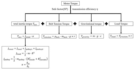
Figure 5.
Motor Torque Calculation Flowchart.
2.3.3. Kinematic Derivation of Nozzle Angle Adjustment Link
The structural function for adjusting the angle of the rotating spray system robot is crucial for enabling its universal application across greenhouses of varying widths and its suitability for column-supported structures. Therefore, detailed theoretical derivation and design calculations are required for this structural function. Adjustment of the nozzle angle is achieved by altering the number of mating holes between the two connecting rods, thereby changing the center distance. The link lengths are derived using trigonometric formulas and interference analysis during mechanical assembly [28], specifically the length of segment BC in Figure 6. To prevent interference during movement and assembly, the horizontal distance between points A and B is set to 42 and the vertical distance to 23 , establishing segments and along with as known conditions. The position of point requires determination. Point lies on the horizontal line . When the nozzle angle forms a 90° angle with the normal line, its position is indicated by the red line in the figure. When the nozzle is adjusted to a angle with the normal line, the positions of all points are shown by the blue line in the figure. To facilitate angle adjustment and ensure an appropriate adjustment range, segment should represent the combined length of two linkages when the angle is while segment AC’ should be the length of a single linkage when the angle is , i.e., . Based on the above known conditions, the following derivation and calculation are performed:
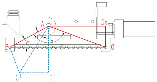
Figure 6.
Linkage geometry for angle adjustment derivation.
List the known conditions and define the unknown parameters: , , . Let segment . For subsequent derivations, define .
First, in , segment AC can be expressed as an algebraic expression containing using the cosine rule for .
Therefore, we can conclude that:
Then we need to find the algebraic expression for segment in in terms of . At this point, it is readily apparent that since , therefore
Then in , by the sine formula, we have , that is:
From , using the cosine formula for : we can solve the simultaneous equations to obtain the following:
Therefore
Since the initially defined optimal rod length relationship is , we set , at this point. Substituting this into Equation (11) along with other known constants yields the equation:
The two roots of the equation can be found as:
The derivation flowchart for the connecting rod length is shown in Figure 7. Kinematic analysis at point C yields the position equation approximated to 124 mm after rounding. This results in a theoretical single linkage length of 62 mm. However, SolidWorks 2021 assembly simulations revealed that this dimension causes excessive elongation of the purple conduit (Figure 4), creating potential collision risks during motion. Iterative reduction in the linkage length established 52 mm as the optimal solution: it positions the mechanism precisely at its angular limit while minimizing conduit length, thereby eliminating interference risks and preventing collisions with greenhouse support columns during operation. Consequently, the linkage pair length was adjusted from 124 mm to 104 mm (BC = 104 mm), fulfilling all functional requirements for robotic angular adjustment.
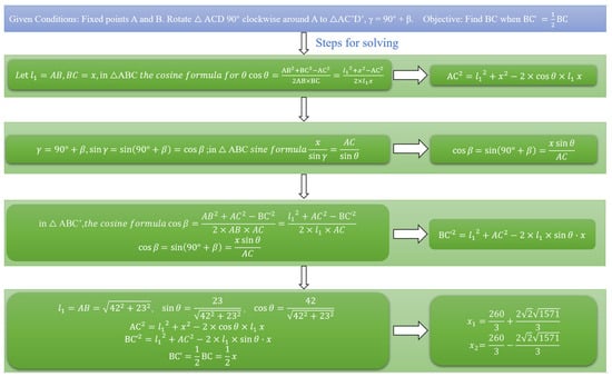
Figure 7.
Flowchart of the Derivation Process.
2.3.4. Static Spray Simulation of Single Nozzle
ANSYS Fluent 2023 R1 was used to simulate the static spray pattern of a single nozzle representative of the physical design (approximated as a conical nozzle, inlet diameter 8 mm, outlet diameter 2.20 mm—switchable outlet implied). The flow domain was a cylindrical air volume (radius 300 mm, height 4200 mm) under normal atmospheric pressure (Figure 8).

Figure 8.
Fluid simulation model setup (Single Nozzle).
The Eulerian multiphase model (water dispersed in air) and k-ω SST turbulence model were employed for transient simulation [29]. Gravity acted downwards. Based on the plunger pump specifications, the water inlet velocity was set to 4 m/s. The simulation ran for 1000 timesteps of 0.001 s each (total simulated time: 1 s).
2.3.5. Static Spray Simulation of Rotating Nozzle Assembly
Prior to simulation, the theoretical relationship between maximum spray distance CD (L), AC represents the height H between point A on the spray nozzle structure and the plant being sprayed. This height is also convenient for manual measurement during actual spraying operations. and nozzle angle relative to normal () was analyzed (Figure 9).
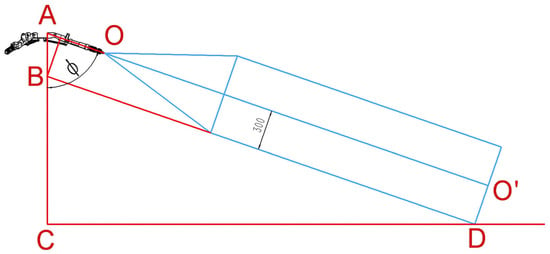
Figure 9.
Geometry for spray height (H) and distance (L) calculation.
As shown in the figure, AC = AB + BC, and both AB and BC can be calculated using trigonometric functions, as follows:
Therefore, the length of AC can be determined, where H represents the height between the spray nozzle and the plant being sprayed:
After simplification, we obtain:
Among these three parameters, knowing any two allows calculation of the third. Both L and H are parameters related to greenhouse dimensions. For a given greenhouse, its width (W) and height (h) are fixed. Common greenhouse dimensions range from 6 to 12 m in width and 2.5 to 6 m in height. The height of the overhead track spray robot is approximately 1.1 m. Adjusting the nozzle height can be achieved by altering the length of the connecting pipe between the high-pressure swivel joint and the one-in-four-out valve. For greenhouses with adjustable overhead tracks, the height can be modified accordingly, though the available adjustment range is constrained by the greenhouse’s maximum height. Therefore, when calculating the H value using Formula (19), it is necessary to select an appropriate angle to prevent the H value from exceeding the installable range.
After performing theoretical calculations for the H value, static simulation spraying with the rotating nozzle can commence. First, to ensure the spray coverage fully spans the greenhouse width, the L should be half the W, i.e.:
Therefore, based on Equations (19) and (20), the corresponding H values for different greenhouse widths at the maximum nozzle angle were calculated, as shown in Table 2. Subsequently, static simulation spraying was conducted at this height using rotating nozzles to test whether the spray coverage could encompass the corresponding greenhouse width and to analyze the resulting wall film thickness.

Table 2.
Required Nozzle Height (H) for Different Greenhouse Widths (W) at .
2.3.6. Dynamic Spray Simulation Under Rotation and Translation
After simulating the spraying range of the rotating nozzle and the thickness of the spray wall film, it became apparent that, due to the influence of the nozzle range and the variation in the angle of incidence between the liquid and the wall, the thickness of the wall film changes to varying extents. To adjust the thickness of the wall film, it is essential to first consider the factors that influence its thickness:
- Spray Coverage: The thickness is higher within the effective spray range and lower near or beyond the boundary. The thickness within the range can be reduced by decreasing the pump output (thus reducing flow/range) or increased by using a higher-power pump.
- Nozzle Angle: This affects the impact angle and distance (H). A smaller angle (), which corresponds to a steeper downward angle at a fixed distance, generally increases deposition density near the base of the sprayer. Conversely, a larger angle () spreads the droplets over a wider area, potentially reducing the local thickness.
- Dynamic Parameters: The rotational speed (RPM) and translational speed (m/s) determine the droplet spatial density. Lower speeds increase the dwell time per unit area, thereby increasing the thickness.
Therefore, it is necessary to analyze the spray behavior of the rotating nozzle under dynamic conditions. First, the spray trajectory of the rotating nozzle during both rotational and translational motion was derived. A coupled motion model of nozzle rotation and cart translation was established using SolidWorks Motion. A rectangular block, attached to the nozzle, represented the spray liquid flow. The tip trajectories were solved for various combinations of rotational speeds (60, 120, and 180 RPM) and translational velocities (0.2, 0.5, and 1.0 m/s) [30]. Rotational speed selection (60/120/180 RPM): These values span the medium-to-high operating range for rotary nozzles (industry-typical range: 100–600 RPM) [31], with a deliberately broad range (60→180 RPM) enabling comprehensive analysis of spraying performance variations. Travel speed configuration (0.2–1.0 m/s):0.2–0.6 m/s: Based on the operational velocity range of overhead rail pesticide application robots (standard industry values) [32,33]; 1.0 m/s: An extended parameter specifically matched to 180 RPM for high-speed performance exploration. Subsequently, spray simulations were conducted in ANSYS Fluent, employing user-defined functions (UDFs) to define the nozzle’s rotation and translation [34]. At atmospheric pressure, the flow field was modeled as a rectangular greenhouse. Transient solutions were obtained using the Eulerian multiphase flow model and the k-ω turbulence model. The wall film thickness was calculated using the Eulerian wall film model. The inlet above the rotating nozzle was set as a velocity inlet with a flow velocity of 4 m/s. Rotation and translation speeds were adjusted via the UDF, and variations in wall film thickness were observed from the simulation results. Finally, the optimal settings for adjusting the wall film thickness were determined to meet the spray requirements of different greenhouses.
3. Results
3.1. Static Analysis Results
Static stress and displacement analyses confirmed the frame’s integrity under operational loads.
Stationary on Ground (Figure 10): Maximum von Mises stress: 45.28 MPa, Maximum displacement: 0.226 mm. Both values are well below the yield strength of 6063-O aluminum (~55 MPa) and acceptable for stiffness.
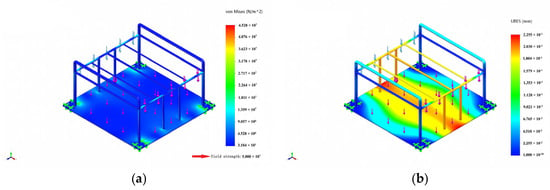
Figure 10.
Static analysis of frame on ground. (a) static stress analysis, (b) static displacement.
Lifted State (Frame Analysis) (Figure 11): Maximum stress: 33.12 MPa, Maximum displacement: 0.299 mm. No yielding occurred.
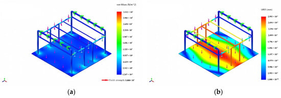
Figure 11.
Static analysis of frame in lifted state. (a) static stress analysis, (b) static displacement.
Lifted State (Hook Analysis) (Figure 12): Maximum hook stress: 42.88 MPa, Maximum displacement: 0.032 mm. Stress is below yield, displacement negligible.
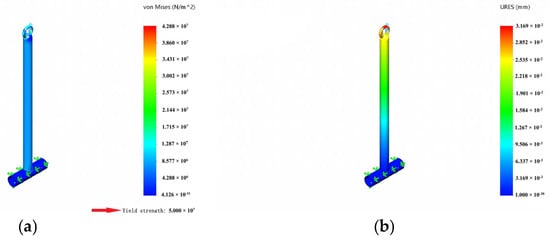
Figure 12.
Static analysis of hook in lifted state. (a) static stress analysis, (b) static displacement.
3.2. Motor Torque Result
Using the formula in Section 2.3.2 and substituting values, the following partial torques and total torque were calculated:
Load Torque:
Gravitational Torque:
Belt Tension Torque:
Load Mass Moment of Inertia:
Driven Wheel Mass Moment of Inertia:
Driven Wheel Mass Moment of Inertia:
Total Mass Moment of Inertia:
Angular Acceleration:
Inertia Torque:
Total Torque:
Calculations indicate that at a maximum rotational speed of 180 RPM, the required torque is 4.35 . The Small electric motor delivers a maximum torque of 55 kgf·cm, equivalent to 5.3955 , sufficient to drive its rotation and satisfy the rotational movement of the spray nozzle.
3.3. Link Length and Angle Relationship
In Section 2.3.3, the link length was derived as 52 mm. Therefore, the center distance between the left and right end holes of the link is set to 55 mm, with a 5 mm spacing between adjacent holes. A total of 12 holes is provided. When the number of aligned holes is 2, the angle to the normal is 92.55° (Figure 13), and the mutual angle between nozzles is 119.8° (Figure 14), maintaining a fundamentally horizontal orientation. For each additional pair of holes on the lower connecting rod, the center distance decreases by 5 mm, and the angle between the three nozzles adjusts by approximately 10°. Meanwhile, the angle between the nozzles and the normal can be adjusted by 6–12°. The adjustment range between nozzles spans from 119.8° to 3.35°, while the angle adjustment range relative to the normal line ranges from 92.55° to 1.94°, effectively allowing replacement within the 0–90° range. When the number of paired holes reaches 12, further angle adjustments can be made using a single connecting rod. Two special cases where additional angle adjustments remain possible are as follows, along with the corresponding angles:
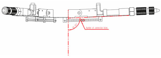
Figure 13.
Nozzle angle relative to normal ().
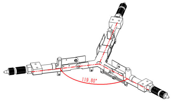
Figure 14.
Angle between adjacent nozzles.
Center distance: 50 mm, nozzle-to-nozzle angle: 13.72°, nozzle-to-normal angle: 7.93°.
Center distance: 45 mm, nozzle-to-nozzle angle: 3.35°, nozzle-to-normal angle: 1.94°.
At the limit position (Figure 15), the nozzles are essentially parallel to the normal. The specific correspondence between the number of paired holes (center distance) and angles is shown in Table 3.
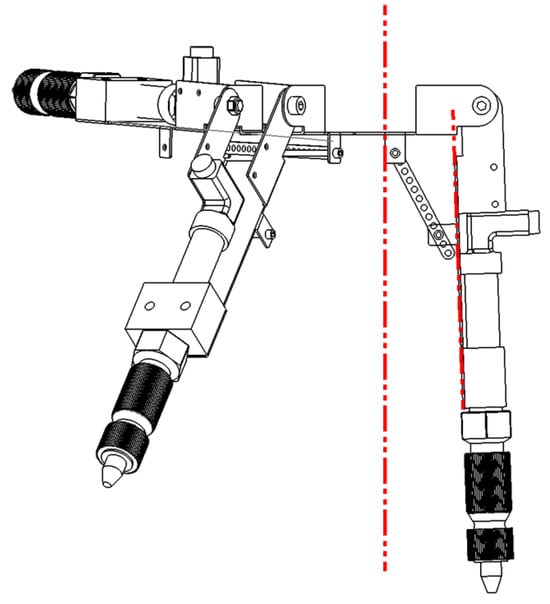
Figure 15.
Nozzle angle at limit position.

Table 3.
Link Center Distance vs. Nozzle Angles.
Adjusting the center distance enables variation from ~92.5° to ~1.9°, providing significant versatility for different greenhouse widths and crop heights without custom multi-row heads. Figure 16 and Figure 17 show the 3D assembly and physical prototype.
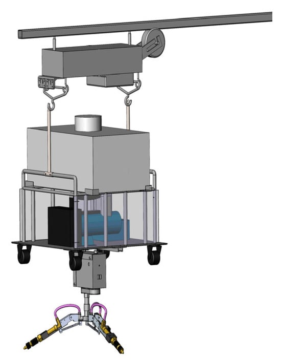
Figure 16.
Three-dimensional Assembly Model.
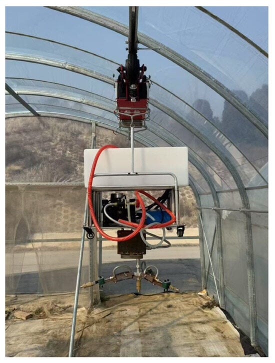
Figure 17.
Physical Prototype.
3.4. Single Nozzle Static Spray Result
The simulation contour (Figure 18) shows wall film thickness after 1 s. Gravity causes higher deposition on the lower wall section. The effective spray range under the given conditions (4 m/s inlet) is approximately 4 m.
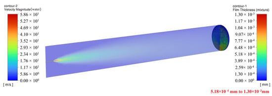
Figure 18.
Static spray simulation contour (Single Nozzle).
3.5. Rotating Nozzle Static Spray Results
W = 6 m, H = 0.78 m, _max ≈ 80.82° (Figure 19): Spray coverage extends to the edge of the 6 m width. The average wall film thickness is approximately 3.50 × 10⁻³ mm.
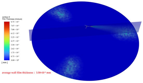
Figure 19.
Spray coverage for W = 6 m.
W = 8 m, H = 0.95 m, _max ≈ 80.82° (Figure 20): Coverage did not fully extend to the edge of the 8 m width. The average wall film thickness was lower (approximately 9.42 × 10⁻⁴ mm).
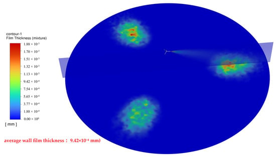
Figure 20.
Spray coverage for W = 8 m.
Thus, this pump/nozzle combination is suitable for greenhouses ≤8 m wide. For smaller widths or specific spray requirements, select an appropriate nozzle angle using Equations (19) and (20) to calculate the corresponding height H for spraying. However, some greenhouses may not allow height adjustment of rotating nozzles while still requiring spray range modification. This section simulates gradually decreasing the nozzle angle in an 8 m wide greenhouse to observe changes in simulated spray coverage and wall film thickness at a constant height.
H = 0.95 m, = 70.93° (Figure 21): The spray range narrows, yet coverage remains within 8 m. The wall film thickness increases compared to the _max value.
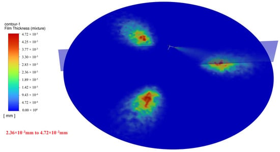
Figure 21.
Spray coverage for = 70.93°.
H = 0.95 m, = 62.15° (Figure 22): The spray range further narrows, coverage still maintained within 8 m. The wall film thickness continues to increase.
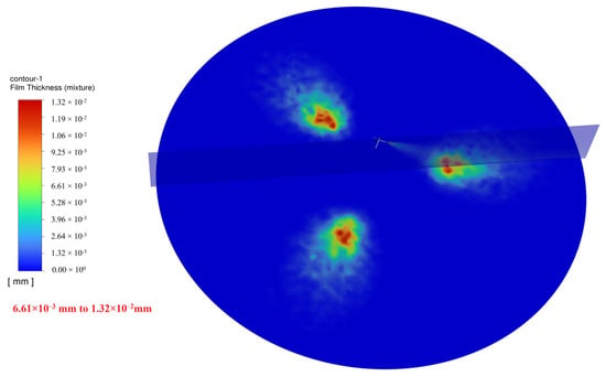
Figure 22.
Spray coverage for = 62.15°.
3.6. Dynamic Spray Results Under Rotation and Translation
3.6.1. Spray Trajectory Lines (SolidWorks Motion)
Comparing the trajectory lines (Figure 23, Figure 24 and Figure 25) reveals: when rotational speed remains constant and movement speed decreases, the degree of intersection between trajectory lines becomes denser; conversely, when movement speed remains constant and rotational speed increases, the degree of intersection also becomes denser. Conversely, the degree of intersection between trajectory lines becomes sparser.

Figure 23.
Trajectory lines at (a) ; (b) ; (c) .

Figure 24.
Trajectory lines at (a) ; (b) ; (c) .

Figure 25.
Trajectory lines at (a) ; (b) ; (c) .
Therefore, it can be hypothesized that the rotational speed of the spray nozzle and the movement speed of the single-wheel transporter influence both the spray coverage area and the thickness of the deposited coating. The following section will conduct dynamic spraying simulations in ANSYS-Fluent, combining rotation with movement, to verify this hypothesis.
3.6.2. Dynamic Spray Fluid Simulation Results (ANSYS Fluent)
Analysis of the simulation results for rotational and translational spraying.
Effect of Translation Speed (Constant RPM = 180):
Speed = 0.5 m/s (Figure 26): Trajectory pattern near-circular. Average film thickness higher.
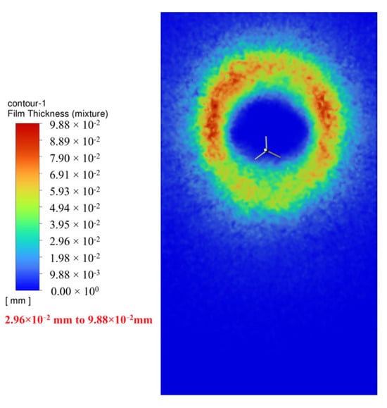
Figure 26.
t = 0.5 s.
Speed = 1.0 m/s (Figure 27): Trajectory pattern elliptical. Average film thickness lower.
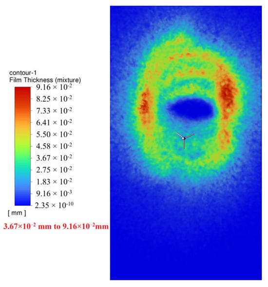
Figure 27.
t = 0.5 s.
Effect of Rotational Speed (Constant Speed = 1.0 m/s):
RPM = 180 (Figure 28): Lower trajectory density. Average film thickness lower.
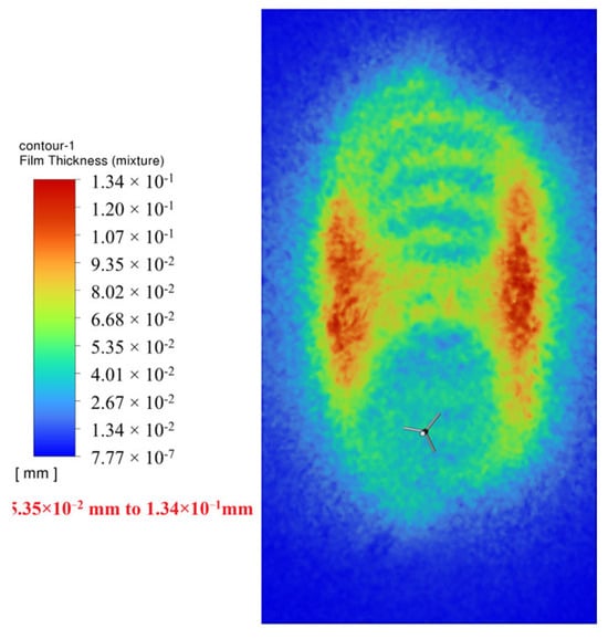
Figure 28.
t = 1.0 s.
RPM = 120 (Figure 29): Higher trajectory density. Average film thickness higher.
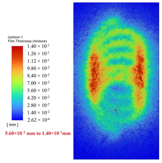
Figure 29.
t = 1.0 s.
Reducing translation speed or rotational speed increases the dwell time per unit area, allowing more droplets to deposit, thus increasing wall film thickness. Increasing either speed decreases dwell time, reducing thickness. Reducing translation speed from 1.0 m/s to 0.5 m/s (50% reduction) at 180 RPM increased average film thickness by 8–9%. Reducing rotational speed from 180 RPM to 120 RPM (33% reduction) at 1.0 m/s increased average film thickness by 8–9%.
Therefore, wall film thickness can be adjusted within operational limits (speed: 0.2–1.0 m/s, RPM: 60–180) by changing either the rotational speed or the translation speed. Increasing either speed decreases thickness; decreasing either speed increases thickness. Both methods offer comparable relative adjustment capability.
4. Discussion
This paper designs a suspended rail rotary spraying robot, primarily composed of a suspended rail travel mechanism and a rotary spraying mechanism. A 3D model was constructed using SolidWorks, and its performance was validated through theoretical derivation and simulation. First, the load-bearing capacity of the rail frame was analyzed in both flat and elevated states to validate its transport performance. Subsequently, motor torque requirements for the rotating spray nozzle were calculated based on motor inertia torque principles. Next, using trigonometric functions and mechanical assembly principles, the link length and mounting position for adjusting the spray nozzle angle were derived. This ensures interference-free operation within the 0–90° adjustment range, providing theoretical support for automated angle adjustment. Finally, SolidWorks-Motion and ANSYS Fluent were employed for spray trajectory coupling and fluid simulation, respectively. Analysis of spray film thickness variations under different rotational and translational speeds revealed controllability through adjusting nozzle rotation and movement speeds.
Compared to linear spray nozzles, rotating spray nozzles offer the following advantages:
- High versatility: Rotating nozzles adaptively adjust spray angles within an 8 m wide greenhouse, accommodating varying greenhouse widths and enhancing universality. Linear nozzles can only alter spray coverage by adjusting nozzle quantity or fixed rods.
- Broad applicability: For greenhouses with support columns, rotary nozzles enable zero-zone-division operation by deploying tracks offset from the centerline, offering superior adaptability. In-line nozzles require dividing the greenhouse into multiple zones, increasing operational complexity. The rotary applicator’s critical components use pesticide-compatible materials, adapting to common agricultural formulations. Both systems demonstrate equivalent chemical resistance.
- Flexible wall film thickness adjustment: Rotating nozzles not only alter film thickness by adjusting pump output and nozzle diameter like linear nozzles but also offer greater flexibility through variable rotation and translation speeds, enhancing adjustment effectiveness.
Beyond prior comparisons, both systems present additional trade-offs:
Cleaning: Linear booms permit direct flushing but consume more water (due to multiple nozzles/long tubing prone to water retention). Rotary sprayers feature quick-connect couplings enabling segmented cleaning, reducing water use while preventing clogs and ensuring thoroughness.
Maintenance: Linear booms require leak vigilance at connections. Rotary systems focus on drive system seal integrity; their polyurethane timing belts and water-isolating seals provide long life, low load, and less frequent maintenance.
Complexity: Rotary sprayers have greater mechanical complexity from added drivetrain parts. However, this does not raise maintenance costs or clogging risk, instead improving portability and operational ease.
Compared to inline nozzles, rotary spray nozzles represent significant advancement, yet automation capabilities can be further optimized through approaches such as:
- Implementing electric actuators for precise automated angle adjustment. The stroke and installation of electric actuators can reference Section 2.3.3 of this paper, which details the determination of linkage positions and length derivation.
- Height adjustment between the nozzle and treated plants. Currently, height increases/decreases are achieved manually by adding connecting tubes between the high-pressure rotary joint and the one-in-four-out valve. A compact lifting mechanism between the hanging cabinet frame and the rotating spray gun could enable more portable height adjustment.
- Incorporate liquid level monitoring and emergency braking. When the liquid level reaches the warning threshold, the application robot immediately powers down and halts operation while recording its current position. After the user refills the liquid, the robot can return to the previously recorded location and resume the unfinished application task.
- Increase the maximum spray range of the rotating spray system. While ≤8 m greenhouses dominate due to superior space efficiency (lower costs, energy use, precise climate control, faster return on investment), larger farms require >8 m structures. The rotary sprayer’s ≤8 m range limit stems from plunger pump pressure/flow constraints. Extending coverage requires upgrading to higher-pressure/flow pumps, enhancing nozzle projection and atomization.
Feasibility & Cost Assessment:
Feasibility: Calculated linear actuator positioning/stroke requires minimal thrust; layout adapts via nozzle adjustment. The central lead screw lifting mechanism enables motor-driven rail adjustment. Capacitive sensors plus a microcontroller will monitor liquid levels. Range extension uses commercially available higher-power pressure pumps for increased pressure/flow. Frame reinforcement, dependent on final specs, is planned.
Cost & Impact: Optimizations will significantly boost automation and performance. Costs are estimated at ~2x current, justified by enabling remote control and enhanced automation. Total rotary system cost remains comparable to linear booms (nozzles are minor cost components), offering small-scale farmers comprehensive functionality at reasonable prices. Future models will provide selectable automation levels. The differences between the current system and the linked spray application system under various metrics are detailed in Table 4.

Table 4.
Differences Between Rotating Spray Application and Concurrent Application.
5. Conclusions
This paper innovatively applies the “straight-to-curve” design concept to spraying systems, replacing traditional linearly arranged nozzles with an arc-curved, rotating nozzle configuration featuring adjustable angles and coating thickness. The research encompasses the following: establishing the system’s 3D model using SolidWorks; performing static simulation (via SolidWorks Simulation) on critical load-bearing components; selecting and calculating specifications for a small electric motor; designing the angle adjustment mechanism and deriving its theoretical basis; conducting trajectory coupling analysis for the rotating nozzle using SolidWorks Motion; and employing ANSYS Fluent for fluid dynamics simulation of spray coating thickness under combined rotational and translational motion. The feasibility and integrity of this rotary spraying system were ultimately validated through physical assembly and testing.
The innovations and conclusions of this paper are as follows:
Design Concept Innovation: The proposed “straight-to-curve” approach provides a case study in reverse thinking for analogous problems.
Research Methodology Innovation: The trajectory coupling analysis method using SolidWorks Motion and the fluid simulation method for combined rotational-translational motion using ANSYS Fluent offer novel perspectives and references for related research.
Strong Product Practicality: The developed rotary spraying robot covers a maximum spraying range suitable for greenhouses within 8 m. Adjustable spraying angles and coating thickness grant it excellent versatility and adaptability, coupled with low cost. This system aligns perfectly with the needs of farmers, as small-to-medium scale cultivation predominantly utilizes 8 m greenhouses (offering moderate space for efficient humidity and temperature regulation, avoiding energy waste associated with large-scale greenhouses; low construction cost ensures high investment return).
Development Potential: The study concurrently proposes optimization schemes for enhanced automation and expanded spraying range (>8 m), providing an upgrade path to meet diverse farmer requirements concerning varying levels of automation.
Author Contributions
Conceptualization, S.H. and J.Y.; methodology, J.Y.; vali-dation, S.H., J.Y. and Y.C.; formal analysis, S.H. and J.Y.; investigation, S.H.; resources, S.H.; data curation, S.H.; writing—original draft preparation, S.H.; writing—review and editing, Y.C.; supervision, Y.C.; project administration, Y.C.; funding acquisition, Y.C. All authors have read and agreed to the published version of the manuscript.
Funding
Mount Taishan Scholars in Shandong Province and Yuandu Scholars in Weifang City, National Natural Science Foundation of China (32072498).
Data Availability Statement
Data will be provided upon request.
Conflicts of Interest
The authors declare no conflicts of interest.
References
- Bhat, S.; Kumar, S. Conventional and Recent Approaches of Integrated Pest Management in Greenhouse Cultivation. In Protected Cultivation; Apple Academic Press: Palm Bay, FL, USA, 2023; pp. 255–274. [Google Scholar]
- Fenibo, E.O.; Ijoma, G.N.; Matambo, T. Biopesticides in Sustainable Agriculture: A Critical Sustainable Development Driver Governed by Green Chemistry Principles. Front. Sustain. Food Syst. 2021, 5, 619058. [Google Scholar] [CrossRef]
- Gao, K.; Wang, S.; Li, R.; Dong, F.; Zheng, Y.; Li, Y. Pesticides in Greenhouse Airborne Particulate Matter: Occurrence, Distribution, Transformation Products, and Potential Human Exposure Risks. Environ. Sci. Technol. 2024, 58, 1680–1689. [Google Scholar] [CrossRef]
- Marangoni Junior, A.; da Costa Ferreira, M. Influence of Working Pressure and Spray Nozzle on the Distribution of Spray Liquid in Manual Backpack Sprayers. Arq. Inst. Biol. 2019, 86, e0442018. [Google Scholar]
- Abioye, A.E.; Larbi, P.A.; Hadwan, A.A.K. Deep Learning Guided Variable Rate Robotic Sprayer Prototype. Smart Agric. Technol. 2024, 9, 100540. [Google Scholar] [CrossRef]
- Fu, Q.; Li, X.; Zhang, G.; Ma, Y. Improved Greenhouse Self-Propelled Precision Spraying Machine—Multiple Height and Level (MHL) Control. Comput. Electron. Agric. 2022, 201, 107265. [Google Scholar] [CrossRef]
- Sammons, P.J.; Furukawa, T.; Bulgin, A. Autonomous Pesticide Spraying Robot for Use in a Greenhouse. In Proceedings of the Australasian Conference on Robotics and Automation (ACRA 2005), Sydney, Australia, 5–7 December 2005; pp. 1–9. [Google Scholar]
- Li, T.; Ni, Z.; Shi, G.; Zhou, J. Design and Testing of an Inter-Row Sprayer in a Chinese Solar Greenhouse. J. Eng. Sci. Technol. Rev. 2020, 13, 32–41. [Google Scholar] [CrossRef]
- Lin, J.; Ma, J.; Liu, K.; Huang, X.; Xiao, L.; Ahmed, S.; Dong, X.; Qiu, B. Development and Test of an Autonomous Air-Assisted Sprayer Based on Single Hanging Track for Solar Greenhouse. Crop Prot. 2021, 142, 105502. [Google Scholar] [CrossRef]
- Zhang, Y.; Cui, H.; Liu, X.; Li, H.; Du, X. Design and Test of Integrated Air Supply and Fine Mist System in Solar Greenhouse. In Advanced Manufacturing and Automation XI; Springer: Singapore, 2021; pp. 629–636. [Google Scholar]
- Lochan, K.; Khan, A.; Elsayed, I.; Suthar, B.; Seneviratne, L.; Hussain, I. Advancements in Precision Spraying of Agricultural Robots: A Comprehensive Review. IEEE Access 2024, 12, 129447–129483. [Google Scholar] [CrossRef]
- Xie, B.-X.; Wang, C.-H.; Ke, J.-Y.; Chang, C.-L. Design and Implementation of a Machine Vision based Spraying Technique for Smart Farming. In Proceedings of the International Automatic Control Conference (CACS 2020), Hsinchu, Taiwan, 4–7 November 2020; pp. 1–5. [Google Scholar]
- Alidoost Dafsari, R.; Yu, S.; Choi, Y.; Lee, J. Effect of Geometrical Parameters of Air-Induction Nozzles on Droplet Characteristics and Behaviour. Biosyst. Eng. 2021, 209, 14–29. [Google Scholar] [CrossRef]
- Zheng, C.; Sun, X.; Sun, Z.; Miao, Y.; Hou, X.; Yang, Y. Design and Experiment of Piezoelectric Adjustment Mechanism for Nozzle Diameter Adjustment. Mech. Syst. Signal Process. 2025, 235, 112901. [Google Scholar] [CrossRef]
- Sun, G.; Xiao, S.; Wu, J.; Yu, S.; Wei, M.; Qin, J.; Zang, M. Study on the Static Stability of Aluminum Alloy Single-Layer Spherical Reticulated Shell. J. Build. Eng. 2024, 84, 108595. [Google Scholar] [CrossRef]
- Kovács, R.C.; Paiss, V.; Vajsz, T.; Horváth, C.; Szászi, I. A Novel Coenergy Based Torque Calculation Method for the Reluctance Motor Drives of Electric Vehicles. In Proceedings of the 7th Global Power, Energy and Communication Conference (GPECOM 2025), Bochum, Germany, 11–13 June 2025; pp. 210–215. [Google Scholar]
- Li, X.; Li, Q.; Tong, W.; Zou, Y.; Hong, N.; Xu, Z. CFD-EDEM Simulations of Droplets in an Airless Rotary Spray Coating Process. Powder Technol. 2024, 439, 119699. [Google Scholar] [CrossRef]
- Chen, W.; Liu, H.; Tang, Y.; Liu, J. Trajectory Optimization of Electrostatic Spray Painting Robots on Curved Surface. Coatings 2017, 7, 155. [Google Scholar] [CrossRef]
- Xu, P.; He, J.; Liao, L.; Gong, J.; Zhao, S.; Xu, K. Experimental Design and Spray Technology Research of Ship Paint Spraying Robot. IOP Conf. Ser. Mater. Sci. Eng. 2019, 612, 032067. [Google Scholar] [CrossRef]
- Wu, J.; Liu, Z.; Yu, G.; Song, Y. A Study on Tracking Error Based on Mechatronics Model of a 5-DOF Hybrid Spray-Painting Robot. J. Mech. Sci. Technol. 2022, 36, 4761–4773. [Google Scholar] [CrossRef]
- Wu, C.; Sun, K.; Chen, X.; Zhang, J.; Zhang, Y. Seismic Performance of Cold-Formed Thin-Walled C-Shaped Steel Composite Wall with Fireproof Straw Boards Cladding. Aust. J. Struct. Eng. 2023, 25, 278–294. [Google Scholar] [CrossRef]
- Yin, S.; He, J.; Zhu, H.; Cui, X.-L. Forming Behavior of Thin-Walled Tubular Components in Hydro-Pressing with Floating Die. Int. J. Automot. Technol. 2025, 26, 1261–1273. [Google Scholar] [CrossRef]
- Tang, S.; Shi, T.; Cao, Y.; Lin, Z.; Wang, Z.; Yan, Y. Simultaneous Identification of Load Torque and Moment of Inertia of PMSM Based on Variable Structure Extended Sliding Mode Observer. IEEE Trans. Power Electron. 2024, 39, 8585–8596. [Google Scholar] [CrossRef]
- Zhao, L.; Chen, H.; Li, Z. Decoupling Control for a Multi-DOF Pneumatic Manipulator Subject to Imbalanced Torques. Nonlinear Dyn. 2024, 112, 3541–3556. [Google Scholar] [CrossRef]
- Jung, W.; Kim, J.; Jang, K.; Yun, S.-H.; Lim, D.; Jin, M.; Park, Y.-H. Vibration, Current, Torque, RPM Dataset for Multiple Fault Conditions in Industrial-Scale Electric Motors under Randomized Speed and Load Variations. Data Brief 2025, 62, 111954. [Google Scholar] [CrossRef]
- Sziki, G.Á.; Szántó, A.; Ádámkó, É. Review of Methods for Determining the Moment of Inertia and Friction Torque of Electric Motors. Acta Polytech. Hung. 2024, 21, 203–218. [Google Scholar] [CrossRef]
- Zhang, X.; Mao, Y.; Sun, X.; Feng, L.; Xiong, Y. Torque Online Correction Control of Switched Reluctance Motor Based on Optimized Torque Sharing Function. IEEE Trans. Energy Convers. 2024, 39, 1750–1762. [Google Scholar] [CrossRef]
- Zakariyah, S. Trigonometric Identities I. In Advanced Mathematics for Engineers and Scientists with Worked Examples; Routledge: Abington, UK, 2024; pp. 80–116. [Google Scholar]
- Zawadzki, D.; Jaskulski, M.; Blatkiewicz, M. 9 Modeling of Two-Phase Flows in Rotating Packed Beds. In Process Intensification; De Gruyter: Vienna, Austria, 2022; pp. 267–306. [Google Scholar]
- Wang, Y.; Wu, H.; Jiang, Y.; Hu, Z. Structural Design and Theoretical Analysis of Jetting Spin Type Lotus Root Digging Machine Based on CFD. Machines 2023, 11, 269. [Google Scholar] [CrossRef]
- Fox, R.D.; Reichard, D.L.; Brazee, R.D. Optimisation of Rotational Speed for Centrifugal Spray Discs in Pesticide Applications. Biosyst. Eng. 2018, 171, 15–24. [Google Scholar]
- Zhang, Y.; Li, X.; Wang, Q.; Liu, C.; Chen, J. Design and Performance Evaluation of an Overhead Rail-Based Precision Sprayer for Greenhouse Vegetables. Biosyst. Eng. 2022, 153, 98–108. [Google Scholar]
- Zhao, L.; Wu, Y.; Zhang, H.; Wang, P.; Guo, X. Real-Time Adaptive Control of Travel Speed for Pesticide Application Robots in Greenhouses. Comput. Electron. Agric. 2021, 187, 106253. [Google Scholar]
- Shi, C.; Liu, Z. Two-Degree-of-Freedom Flutter Wing Aerodynamic Characteristics Analysis Based on Fluent. In Proceedings of the Asia-Pacific Conference on Software Engineering, Social Network Analysis and Intelligent Computing (SSAIC 2024), New Delhi, India, 10–12 January 2024; pp. 554–558. [Google Scholar]
Disclaimer/Publisher’s Note: The statements, opinions and data contained in all publications are solely those of the individual author(s) and contributor(s) and not of MDPI and/or the editor(s). MDPI and/or the editor(s) disclaim responsibility for any injury to people or property resulting from any ideas, methods, instructions or products referred to in the content. |
© 2025 by the authors. Published by MDPI on behalf of the International Institute of Knowledge Innovation and Invention. Licensee MDPI, Basel, Switzerland. This article is an open access article distributed under the terms and conditions of the Creative Commons Attribution (CC BY) license (https://creativecommons.org/licenses/by/4.0/).