Abstract
At present, traditional X-ray inspection is used to inspect the welds of the bottom, barrel section and short shell parts of the launch vehicle, which has the disadvantages of low automation, complicated process and low efficiency, and cannot meet the fast-paced development needs of multiple models at present. Moreover, the degree of digitization is low, the test results are recorded in the form of negatives, data statistics, storage and access are difficult, and the circulation efficiency is low, which is not conducive to product quality control and traceability; At the same time, it cannot adapt to and meet the needs of digital and intelligent transformation and development. In this paper, a dual-robot collaborative digital radiographic inspection system for rocket tank welds is developed by combining dual-robot control technology and digital radiographic inspection technology. The system can be directly applied to digital radiographic inspection of tank bottom, barrel section and short shell welds of multiple types of launch vehicles; meanwhile, the dual-robot path planning technology based on the dual-mode is studied. Finally, the imaging software platform based on VS and Twincat3.0 VS2015 software combined with QT upper computer is designed. Experiments show that compared with the existing traditional ray detection methods, the detection efficiency of the system is improved by 5 times, the image sensitivity reaches W14, the resolution reaches D10, and the standardized signal-to-noise ratio reaches 128, which far exceeds the requirements of process technology A, and meets the current non-destructive detection work of multi-model rocket tank welds.
1. Introduction
In recent years, to keep pace with the development trends of international aerospace welding technology and meet the requirements of new-generation space launch vehicles, aerospace manufacturing companies both domestically and internationally have actively adopted friction stir welding (FSW) [1,2,3] for the welding of aerospace tank structures. The fuel tanks of China’s currently operational launch vehicles are primarily fabricated using aluminium alloy plates through conventional welding [4,5]. During the welding process, factors such as temperature, air humidity, operator skills, and welding procedures can influence the weld quality, inevitably leading to various types of defects in the weld zone [6,7]. Weld defects are categorised into five types: cracks, incomplete penetration, incomplete fusion, porosity, and slag inclusions. The presence of these welding defects can adversely affect the safety and performance of the fuel tank, and in severe cases may even lead to fuel leakage, an explosion [8,9,10], or mission failure. Therefore, internal defect detection of welds is essential during the manufacturing process of fuel tanks. For Grade I welds, 100% non-destructive testing is required.
With the advancement of industrial robotics technology, automated inspection equipment integrating non-destructive testing (NDT) with industrial robotics has emerged [11,12]. For instance, the University of Dayton in the United States developed a fully automated ultrasonic inspection system for detecting embedded defects in turbine engine components [13]. This system comprises a six-degree-of-freedom robotic arm, a rotating water tank turntable, phased array ultrasonic instruments, an automatic probe changer, “intelligent” probes, collision avoidance hardware, an industrial computer, a Windows-based operating system, and a digital vision system. Compared to traditional three-degree-of-freedom ultrasonic inspection equipment, this device offers advantages such as high flexibility, precision, wide motion range, high automation, and ease of maintenance. Its drawbacks include high production costs and challenges in mass production. This system can inspect components with large dimensions, complex structures, and highly curved planar surfaces. The robotic ultrasonic inspection equipment developed by German Robotics Systems [14] features an X-axis travel distance of 8.5 m, Y-axis travel distance of 2.2 m, Z-axis travel distance of 3.5 m, maximum scanning speed of 0.6 m/s, and can accommodate ±50° curvature within the X-Y plane. It is suitable for inspecting components with large planar curvature and substantial structural dimensions. The current workplace lacks compatible, efficient, and intelligent process equipment [15,16,17], severely limiting the application of advanced non-destructive testing technologies such as digital radiography [18,19]. This issue is particularly pronounced when inspecting curved rocket fuel tank welds or confined spaces. Without efficient, intelligent inspection equipment, reliance on manual operation often significantly increases the skill requirements and workload for inspectors, sometimes exceeding the difficulty of traditional methods. This not only hinders the full utilization of digital radiography’s advantages but also increases process complexity, labor intensity, and accidental radiation risks [20,21]. Manual operation can even yield lower inspection efficiency than traditional techniques. Furthermore, the upfront costs of these new technologies exceed those of conventional methods. Without cost-offsetting efficiency gains, widespread market adoption remains challenging. Relying solely on traditional manual inspection methods prevents the effective implementation of these novel NDT technologies.
With the continuous increase in routine high-intensity and high-density research, development, and launch missions, the workload of rocket fuel tanks is constantly growing. As the main structural component of a launch vehicle [22,23,24], the rocket fuel tank primarily serves to store rocket fuel and is typically composed of three major structural components, the tank bottom, short shell, and cylinder section, as shown in Figure 1. Currently, welds in the tank bottom, cylinder section, and short shell components are primarily inspected using traditional film photography [25,26,27]. This method has low automation, requires manual inspection by multiple personnel, and is cumbersome and inefficient, failing to meet the fast-paced development demands of multiple rocket models. Additionally, it has low digitalisation, with inspection results recorded on film, making data statistics, storage, retrieval, and circulation inefficient [28], which is unfavourable for quality control and traceability. It also cannot adapt to or meet the demands of digitalisation and intelligent transformation.

Figure 1.
Rocket fuel tank structural components [29].
Compared with the traditional film-based X-ray radiography inspection and digital X-ray imaging inspection, the digital X-ray inspection process is simpler, eliminating steps such as film preparation, development, and waste liquid disposal. The X-ray inspection process flow is shown in Figure 2. Additionally, this technology facilitates automated inspection, real-time monitoring, data management, and subsequent data analysis and sharing [30,31]. Therefore, the development of this technology provides an effective solution to address the efficiency bottleneck in the inspection of welds in rocket fuel tanks. However, due to the diverse structural characteristics of rocket fuel tank welds, existing digital radiographic inspection technologies have not yet achieved automated image acquisition of digital radiographic images of rocket fuel tank welds.

Figure 2.
Comparison of inspection processes.
This paper addresses the structural characteristics of rocket tank welds. To enhance the efficiency and accuracy of radiographic testing for rocket tank welds, a dual-robot collaborative digital radiographic inspection system for rocket tank welds was designed, achieving an automated inspection process for rocket tank welds. For dual-robot path trajectory planning, a dual-mode switching collaborative detection strategy is proposed. The dual modes primarily encompass loose collaboration and tight collaboration with full constraints. During loose collaboration, collision and interference issues are primarily addressed, mainly utilizing an improved artificial potential field method for dual-robot path planning. In tight collaboration with full constraints, detection consistency is the primary consideration, with relevant constraints established based on the digital radiographic inspection process. The robot detection paths generated by the dual-mode approach are integrated to complete the dual-robot detection path trajectory planning. Finally, an imaging software platform is designed based on the combination of VS and Twincat software with a QT host computer interface.
This research innovatively employs dual-robot control technology integrated with digital radiography to achieve automated non-destructive testing of rocket tank welds. A dual-robot collaborative inspection strategy featuring dual-modality switching is proposed, enabling path trajectory planning for both robots. An imaging software platform was designed, integrating VS and Twincat software with a QT host computer interface. This platform encompasses functional modules for detector control, X-ray machine control, mechanical motion control, image acquisition, image processing, and information display. Ultimately, it forms an intelligent imaging software platform integrating imaging, image processing, and mechanical motion into a unified detection and control system. The designed dual-robot collaborative digital radiographic inspection system for rocket tank welds enables defect detection across multiple product weld types, including arc welds, circumferential welds, longitudinal welds on cylindrical sections, and butt welds on semi-tanks. This enhances inspection efficiency for rocket tank welds while reducing manual labour intensity.
2. Overall Scheme Design of the Dual-Robot Digital Radiographic Inspection System
2.1. Scheme Design
The rocket fuel tank weld seam digital X-ray inspection system based on dual-robot collaboration consists of an X-ray imaging system, a mechanical motion system, a control system, and related accessories, as shown in Figure 3. Among these: The X-ray imaging system comprises a PC, an X-ray machine, an X-ray machine controller, a high-voltage generator, an imaging plate, and imaging software, primarily responsible for imaging and defect detection of rocket fuel tank weld seams; The mechanical motion system comprises an X-ray machine robot, an imaging plate robot, a synchronous lifting mechanism, a seventh-axis track, and a turntable. The turntable is mounted on the lifting mechanism and can move vertically and rotate 360 degrees. The X-ray machine robot and the imaging plate robot are installed on the same seventh-axis track and move via the robot’s seventh-axis control; The control system primarily includes a Beckhoff PLC controller, electrical control cabinet, operator console, limit switches, upper-level display screen, servo drives, servo motors, rotary encoders, and robot control cabinet. The robot is optionally equipped with Beckhoff EK1100 EtherCAT communication couplers for communication with the Beckhoff controller; The X-ray machine controller and imaging software use the ADS multi-threaded communication protocol, with Beckhoff control as the core, programmed using TWINCAT software. This integrates the operation of the X-ray machine controller, imaging software, lifting mechanism, turntable, and the robot body and seventh-axis movements, with logically designed timing sequences to achieve the automatic inspection process for rocket fuel tank welds.
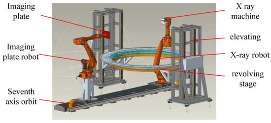
Figure 3.
Dual-robot collaborative digital X-ray inspection system for rocket fuel tank welds.
2.2. Dual-Robot Mechanical Motion System
Based on the structural design of rocket fuel tanks and the requirements for digital radiographic testing, the dual-robot mechanical motion system consists of a turntable assembly, a lifting assembly, robots, and a seventh axis. The robots selected are from the KUKA KR50 R2500 series, with a motion range of 2501 mm. The specific working space is shown in Figure 4. By employing relevant software combined with the Monte Carlo method and robot models for simulation analysis and design, the working area of the dual-robots can accommodate digital X-ray inspection of rocket fuel tanks of multiple models.
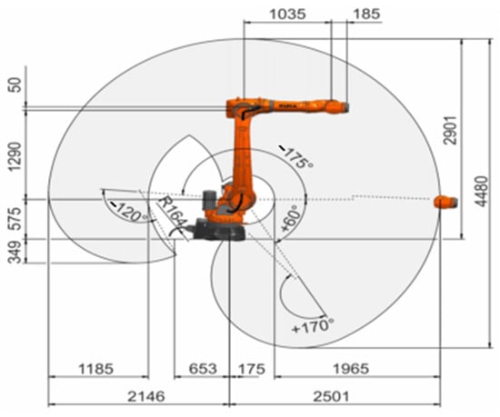
Figure 4.
KUKA KR50R2500 Working Space [32].
2.3. Control System
The control system primarily consists of the device layer, control layer, and operation layer. The two robots are the X-ray machine robot and the imaging plate robot. X-ray machines and imaging plates are installed at the ends of the dual-robots. After path and trajectory planning, they achieve coordinated movements. Combined with the rotation and elevation of the turntable, they complete the automatic detection process. The robot controller and Beckhoff controller establish EtherCAT communication [33] to enable external startup and robot program path selection. The lifting mechanism and turntable are remotely controlled via the upper-level computer display and remote controller. Robot control is performed using a teach pendant and the upper-level computer, with all information ultimately displayed on the upper-level computer screen. The control system architecture is shown in Figure 5. The imaging software communicates with the Beckhoff controller [34] via the automation device specification communication protocol [35] to facilitate logical signal interaction during the automated inspection process.
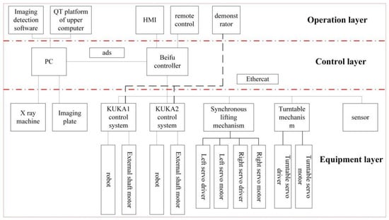
Figure 5.
Overall architecture of the control system.
2.4. Digital X-Ray Imaging System
2.4.1. Principles of Digital Radiography
When X-rays pass through an object being inspected, the regions with defects have different absorption capabilities for X-rays compared to defect-free regions. The intensity of X-rays passing through defect-free regions differs from that passing through defect-containing regions. Therefore, by analysing the intensity differences in X-rays after passing through the object, defects within the object can be detected. Figure 6 illustrates the principle of X-ray digital inspection. The main feature of digital radiography technology is the use of imaging plates instead of film as the primary medium for receiving X-rays, and the transmission of the received X-ray radiation information in the form of electrical signals. These electrical signals are processed by imaging software to form digital images, which can be directly observed and also provide the foundation for intelligent weld defect recognition.
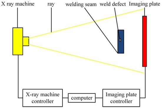
Figure 6.
Principle of Digital Radiography [36].
2.4.2. Digital Radiography Imaging System Hardware
To ensure that all image performance metrics of the dual-robot digital radiographic inspection system meet standard requirements and achieve the same level of detail detection capability as the original weld inspection system, the inspection system was selected based on a comprehensive evaluation of performance metrics, cost-effectiveness, and brand reputation. The imaging system comprises the CF225 small-focus X-ray machine from GULMY Company (Surrey, UK) and the 3025 imaging plate from Varex Company (Salt Lake City, UT, USA), with specific parameters detailed in Table 1.

Table 1.
X-ray machine and imaging plate parameters.
3. The Collaborative Control Method of the Dual-Robot System
3.1. Dual-Robot Cooperative Control Hardware Configuration Connection
The dual-robot collaborative control connection is shown in Figure 7. Industrial robots are multi-jointed machine device designed for industrial applications, capable of free programming and operation according to established programs. An industrial robot consists of a robot body, control cabinet, connection cables, software, and peripheral devices. The dual-robot collaborative control adopted in this paper uses Ethercat as the communication protocol, with the ray-moving robot as the master station and the imaging board-moving robot as the slave station. Control and motion can be operated by the Beckhoff controller and teach pendant, with the program written on the teach pendant. The program can run autonomously or be externally triggered via the Beckhoff controller. Additionally, a seventh axis and a mobile track are added to each robot body to accommodate products of different sizes, thereby achieving automated digital X-ray inspection of rocket fuel tank welds for multiple models.
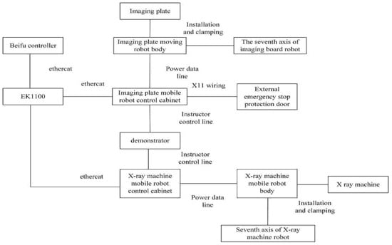
Figure 7.
Schematic diagram of dual-robot collaborative control connection.
3.2. Path and Trajectory Planning for Dual-Robot Collaborative Inspection
Currently, in the digital X-ray inspection process of rocket tank welds, the X-ray machine and imaging plate in the digital X-ray inspection system are fixedly installed at the end of two robots. Path planning for the two robots is then performed using online teaching. However, due to the diverse models and types of rocket tanks, the online teaching cycle is lengthy and prone to interference and collisions between the robots and the rocket tank products. Based on these issues, this paper proposes a dual-mode switching dual-robot collaborative inspection strategy. For the critical points in the digital ray inspection process of rocket fuel tank welds by two robots, corresponding mode switching rules are designed. The dual modes primarily include loose coordination and tight coordination with full constraints. During loose coordination, collision and interference issues are primarily considered, with the improved artificial potential field method applied to achieve path planning for the two robots. In tight coordination with full constraints, detection consistency issues are primarily considered, with relevant constraint conditions established based on the digital radiography inspection process. Finally, the robot inspection paths generated by the dual-mode system are integrated, and a process procedure is designed for the dual-robot digital ray inspection system to achieve an automated and integrated digital ray inspection process for rocket tank weld seams. The specific process is shown in Figure 8.
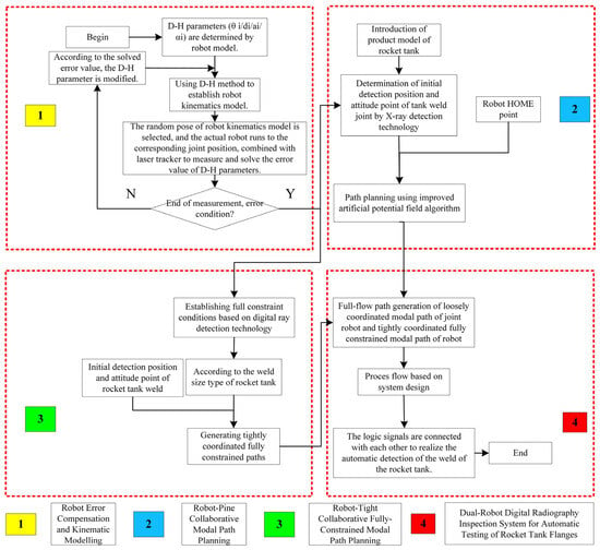
Figure 8.
Path trajectory planning for dual-robot collaborative detection.
3.2.1. Dual-Robot Loose-Cooperative Mode
As shown in Figure 9, the flowchart of the path trajectory planning process for the dual-robot loose coordination mode is presented. In this study, the sphere-cylinder enveloping method is adopted to establish the enveloping model for obstacles, while the rectangular prism enveloping method is used for obstacles. To meet the constraints of the mechanical arm joints and linkages, as well as real-time requirements, a rapid collision detection method for mechanical arms is proposed based on the enveloping model, and collision analysis tests are conducted.
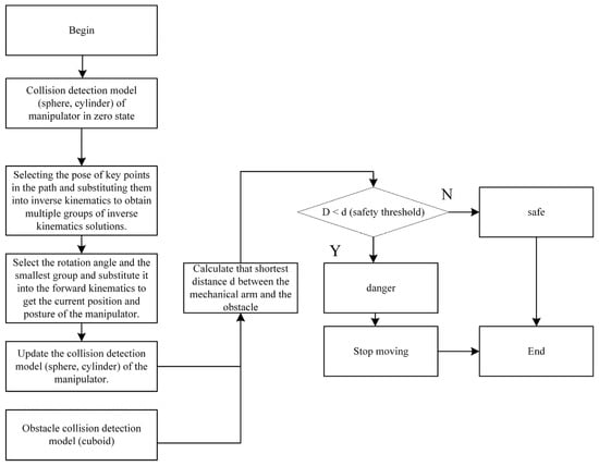
Figure 9.
Path trajectory planning for dual-robot loose coordination mode.
Additionally, as the angles of each joint change during motion, the collision detection model must also adapt accordingly. Based on the actual task of the robotic arm, the specific position information of the end-effector can be determined. After obtaining the position information, the D-H algorithm and inverse kinematics formulas are applied to calculate the angles of each joint. By substituting the pose into the previous inverse kinematics joint formulas, the angles of all joints of the robotic arm at that position and pose can be obtained. Select the joint rotation angle and the smallest set of inverse kinematics solutions, substitute them into the forward kinematics equations to determine the positions of each joint, and combine the joint positions with the joint angles to determine the positions of each link. Update the robot arm’s pose and use collision detection algorithms with the obstacle model to determine whether the robot arm collides with the obstacle model.
3.2.2. Dual-Robot Tight Cooperative Mode
According to the principle of optimal sensitivity in radiographic testing, a single-wall transmission method is adopted with the X-ray machine inside and the imaging plate outside. The center of the X-ray beam from the X-ray machine should be perpendicular to the center of the welded joint. The distance f between the X-ray machine and the surface of the rocket tank flange weld, the focal length d of the X-ray machine, and the distance b between the product and the imaging plate should meet the following requirements [37]:
To ensure the safety of the rocket fuel tank product and the robot during the inspection process, the distance b from the product to the imaging plate should be greater than 100 mm. The focal spot size d of the X-ray machine is 0.4 mm. Using the above formula, the distance from the X-ray source to the product surface should be greater than 130 mm. Since the cone angle of the directional X-ray tube is 40 degrees, to increase the single-pass penetration length while ensuring adequate penetration thickness, the distance f from the X-ray machine to the surface of the rocket fuel tank flange weld is set to 500 mm.
Dual-robot tight collaborative control is based on the KUKA Robot team software 8.6.2, where multiple robots or robots with additional axis motion systems can collaborate. The GEOLINK SLAVE command in Robot team is used to ensure that the trajectories of the robots are coordinated in both time and geometry (time and/or geometric coupling) during collaboration.
3.3. Dual-Robot Collaborative External Start
Due to the radioactive nature of X-rays, the entire inspection process must be conducted in an unmanned lead-lined room. All operational procedures are performed outside the lead-lined room, with the dual-robots activated via an external control system. The robot program is written on the robot teach pendant and communicated via the EtherCAT bus to the Beckhoff controller for retrieval, start, and stop. The control system employs dual-robot collaborative control, requiring separate program development for each robot. The X-ray machine robot is designated as the master station, and the imaging plate robot as the slave station. During collaborative motion, the imaging plate robot follows the movements of the X-ray machine robot.
The robot program primarily consists of an external start-up program, a dual-robot collaborative motion program, and individual path trajectory programs for each robot.
The external startup program primarily fulfils the functions of retrieving, starting, and stopping the robot program through trigger signals and program numbers sent by the Beckhoff controller Figure 10 shows the signal interaction points between the robot control system and the Beckhoff PLC. The external startup method for the robot in the rocket fuel tank weld seam digital X-ray inspection system based on dual-robot collaboration designed in this paper includes the following steps:
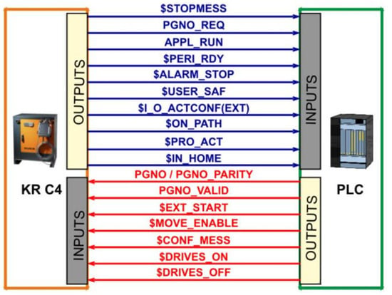
Figure 10.
Robot Control and PLC Signal Interaction Points [38].
- (1)
- In robot T1 mode, enter CELL.SRC (the program number is defined by SWITCH CASE) and run until reaching the EXT_AUT mode;
- (2)
- The PLC sends a signal to MOVE_ENABLE upon power-on;
- (3)
- After sending the signal to MOVE_ENABLE for 0.5 s, the PLC sends the signal to DRIVERS_OFF on the robot;
- (4)
- After sending the signal to DRIVERS_OFF for 0.5 s, the PLC sends the signal to DRIVERS_ON, and the robot then sends the PERI_RDY signal back to the PLC, after which the PLC disconnects the DRIVERS_ON signal;
- (5)
- The PLC sends an EXT_STAR (pulse signal) to the robot to start it;
- (6)
- When the PLC receives the PGNO_REQ signal from the robot, the PLC sends the program number to the robot;
- (7)
- After sending the program number for 0.5 s, the PLC sends a PGNO_VAILD pulse signal to the robot, at which point the program number becomes active.
To stop the robot: Disconnect the DRIVERS_OFF signal.
External robot startup: Repeat steps (3), (4), and (5).
Reset fault: Send a pulse signal to CONF_MESS (pulse signal).
The dual-robot collaborative control program is based on KUKA’s Robot team software to enable multiple robots to work together in the system. When robots collaborate, their trajectory movements are coordinated in both time and geometry (time and/or geometric coupling). The robot path trajectory programs are written using common control commands such as point-to-point, linear motion, and circular motion available on the teach pendant to achieve the respective path trajectories.
4. Inspection Process and Imaging Software Design
4.1. Inspection Process Design
The workflow for digital X-ray inspection of rocket tank welds primarily includes three stages: inspection preparation, inspection implementation, and post-processing. The specific steps are shown in Figure 11.
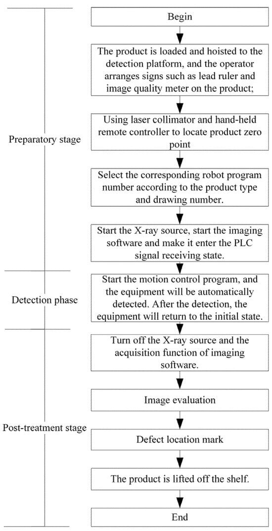
Figure 11.
Product Inspection Process Flow.
According to the detection process flow, the motion control program flow is as follows: First, the turntable moves up to a height of 1500 mm. Once in position, the X-ray machine robot begins operation and continues until it reaches the inspection point of the product being tested. Once the X-ray machine robot is in position, the turntable descends according to the product being inspected. After descending to the correct position, the imaging plate robot moves into action, travelling to the inspection point of the product being tested. It then sends a signal to the imaging software via the PLC, which initiates the data acquisition process. After image acquisition is complete, the imaging software sends a signal to the PLC controller. Upon receiving the signal, the PLC controller directs the robot to move to the next inspection position. Once both robots have reached their respective inspection positions, the PLC sends a signal to the imaging software, which begins image acquisition. This process repeats in a loop until all inspection positions have been inspected. After all inspections are complete, the imaging plate robot first moves back to the HOME position. Once the imaging plate robot is in position, it sends a signal to the PLC controller, The PLC controller controls the turntable to rise to 1500 mm. Once the turntable reaches the position, it sends a signal to the PLC controller. The PLC controller then controls the X-ray machine robot to perform its actions until it returns to the HOME point. Once the X-ray machine robot is in position, it sends a signal to the PLC controller. The PLC controller controls the turntable to descend until it reaches the loading/unloading height of the product to be tested, at which point the entire motion control program sequence is complete. The following is the entire inspection motion sequence.
(1) Before inspection, rotate the turntable to the pre-set starting position with the turntable approximately 100 mm above the ground. As shown in Figure 12. The inspection personnel use a crane to lift the product to be inspected and place it on the turntable.
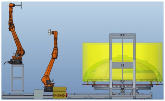
Figure 12.
Product Preparation.
(2) The lifting platform raises the turntable to the designated position. The product is approximately 1500 mm above the ground. As shown in Figure 13.
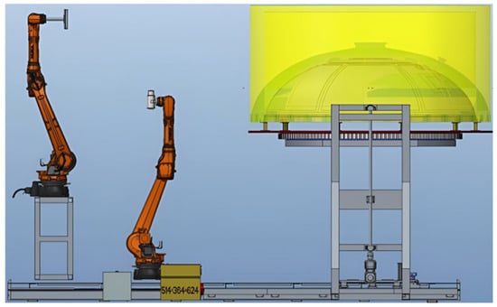
Figure 13.
Turntable Rising.
(3) The X-ray machine robot moves to the position directly below the turntable, and the imaging plate robot moves to the outer side of the turntable. As shown in Figure 14.
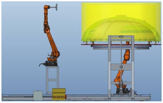
Figure 14.
Robots in Position.
(4) The turntable descends to the predetermined height. As shown in Figure 15. The X-ray machine robot and imaging plate robot execute their respective programs to begin inspecting the product welds. The turntable moves up/down and rotates according to the pre-set process sequence, sequentially completing the inspection of each weld. During this process, the bottom of the box remains at a fixed height of approximately 2.2 m, while the height of the cylinder section varies between approximately 0.7 m and 2.7 m.

Figure 15.
Inspection Implementation.
(a) Box bottom circumferential weld: The robot remains stationary, and the turntable performs stepwise rotation to complete the weld inspection.
(b) Circular ring longitudinal seam: The robot starts from the beginning of the longitudinal seam and moves along the seam at a step distance equal to the length of one penetration. After completing the inspection of a single weld, the turntable rotates to position the next weld for inspection. The robot repeats the above motion trajectory to complete the inspection of the next weld. This cycle is repeated six times to complete the inspection of the circular ring.
(c) Cylinder segment longitudinal seam: The robot remains stationary, and the workbench descends in steps equal to the length of one penetration from the starting point. After completing the inspection of a single weld seam, the turntable rotates 90°, simultaneously rising to the starting height to inspect the next weld seam. The above steps are repeated until the inspection is complete.
(5) After inspection is complete, the turntable rises, and the X-ray machine robot and imaging plate robot move to their initial positions outside the turntable. The turntable descends. As shown in Figure 16. The operator removes the product from the turntable.
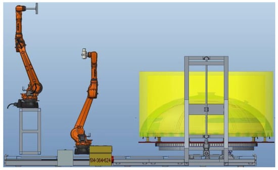
Figure 16.
Inspection Completed.
4.2. Imaging Software Design
4.2.1. Overall Design of the Imaging Software Intelligent Platform
A digital X-ray inspection system for rocket fuel tank welds based on dual-robot collaboration can effectively improve the inspection efficiency and quality of rocket fuel tank welds. However, integrated software platforms that can be applied to industrial production and achieve dual-robot control and digital X-ray inspection are still rare. Therefore, based on the developed dual-robot collaborative rocket fuel tank weld seam digital X-ray inspection system, this paper designs an imaging software platform tailored for rocket fuel tank weld seams, which is applied to rocket fuel tank weld seam inspection to achieve real-time image acquisition of weld seams, dual-robot control, and online detection of weld seam defect status during the inspection process. This paper designs the imaging software platform using VS and Twincat software combined with a QT-based upper-level machine interface, completing the development of functional modules such as detector control, X-ray machine control, mechanical motion control, image acquisition, image processing, and information display. Ultimately, an integrated intelligent detection and control platform combining imaging, image processing, and mechanical motion is formed. Figure 17 shows the overall architecture of the imaging software platform.
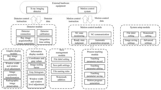
Figure 17.
Overall architecture of the imaging software platform.
The imaging software first divides the system into functional modules, which are designed and tested independently. Modular design enhances the software’s scalability, facilitates the addition of new features in the future, and improves maintainability. The imaging software platform is divided into the following modules: detector module, image display module, information display module, data storage and management module, motion control module, process teaching module, and system settings module. The functions of each module are described below.
Detector Module: Establishes communication with the X-ray imaging detector to control the detector, monitor its status, and acquire X-ray images.
Image Display Module: Performs transformations on the acquired X-ray images and displays them in a window.
Information Display Module: Displays real-time coordinate information and grey-scale values of the pixel where the mouse cursor is located, window width and position information of the image, and the grey-scale histogram of the entire image.
Save and Management Module: Provides functions such as setting the save path and folder hierarchy, file naming rules, and image watermark settings.
Motion Control Module: Connects to the device’s motion control system, monitors the status of the motion system in real time, and receives commands from the motion control system to achieve automatic acquisition functionality.
Process Teaching Module: During the process teaching process of the device, records information about each teaching position, stores process teaching tables, and generates executable code programs for the motion control system based on the recorded teaching information with a single click.
4.2.2. Imaging Software Intelligent Platform ADS Communication Design
- (1)
- VS Software Program Setup
The ADS communication program design uses the C++ programming language to call the TC ADS DLL library provided by Beckhoff to build communication functionality. The TC ADS DLL provides the capability to communicate with other ADS devices through the CAPI interface via the TwinCat router. To implement an ADS client, the following basic steps are typically required: connecting to the PLC (i.e., connecting variables, refreshing data, and releasing variables), and disconnecting from the PLC. The ADS communication principle is illustrated in Figure 18, showing how VS software acts as a client to access data variables in the memory of the Beckhoff master controller on the PC, performing data exchange, processing, and decision-making to achieve system communication, control, and monitoring. Additionally, it supports auxiliary parameter settings, manual operations, and process status display.
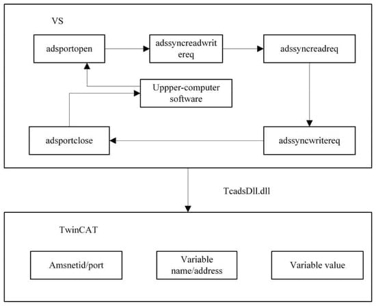
Figure 18.
ADS Communication Principle.
The ADS program primarily includes configuration functions, communication port opening functions, automatic address acquisition functions, data read/write functions, and communication port closing functions. The program structure is shown in Figure 19.

Figure 19.
ADS Program Structure.
- (2)
- Lower-level machine development
- (1)
- Lower-level machine program architecture setup
In the TwinCAT software system architecture, the lower-level machine program is developed within the TwinCAT System Manager and TwinCAT PLC environment. It primarily handles data acquisition, functional control, and information feedback. TwinCAT can replace traditional programmable logic controllers (PLC) to perform real-time control tasks. It features multi-task real-time control, enabling the system to schedule tasks for various devices in an orderly manner. At the same time, it can send tasks to multiple logic controllers and ensure they operate independently without interference. TwinCAT also offers excellent compatibility, supporting common industrial communication protocols such as Profibus, Ethernet, and Modbus RTU.
- (2)
- Lower-level machine program design
The VS software program communicates with the lower-level B&R master controller PLC via ADS communication. The lower-level B&R master controller acts as an intermediary between the upper-level QT software 5.11 and various devices. When the corresponding function button is pressed on the upper-level QT software interface, the corresponding logic signals change. The lower-level B&R master controller then receives the changed logic signals and executes the corresponding function program to complete the task. Task priority settings Add tasks in the Task Configuration section, as shown in Figure 20, and associate them with the corresponding programs. Set the priority and runtime cycle for each task.

Figure 20.
Priority Settings.
4.2.3. Imaging Software Control Process Design
Based on the functional requirements, parameter acquisition, and safety settings in the detection process, the imaging software control process flow is designed as shown in Figure 21.
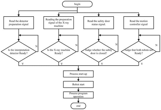
Figure 21.
Imaging Software Operation Flow.
5. System Motion Simulation and Application Testing
5.1. System Motion Simulation
According to the requirements of the digital X-ray inspection process, the centre of the X-ray source is 800 mm from the weld seam, the surface of the imaging plate is 200 mm from the weld seam, and the product weld seam is located between the X-ray source and the imaging plate. The line connecting the centre of the X-ray source and the centre of the imaging plate is always perpendicular to the weld seam. Motion simulation was conducted for a typical product, and the simulation results are shown in Figure 22, which demonstrate that the motion requirements for inspection are met.
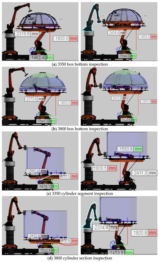
Figure 22.
Typical product inspection motion simulation.
5.2. System Application Testing Typical Product System Application Experiment
The designed dual-robot collaborative rocket tank weld seam digital X-ray inspection system was applied to typical rocket tank products, as shown in Figure 23. The imaging plate can be positioned at a certain distance from the weld seam and only needs to be tangent to the weld seam to complete the inspection. Additionally, based on the inspected product, the effective detection range of the imaging plate and the inspection process parameters for different regions were determined to ensure consistent image quality and detection sensitivity requirements. The use of a dual-robot collaborative approach ensures consistency in inspection distance.
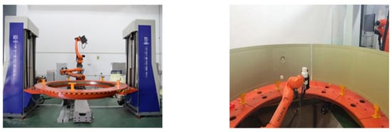
Figure 23.
System application testing.
Digital radiographic testing was conducted on different products, welding methods, and weld thicknesses using a detection system. The sensitivity, resolution, and normalised signal-to-noise ratio of digital radiographic images were used as testing criteria. The testing standards must meet the Grade A requirements of the process technology, which specify that image sensitivity must reach W13, resolution must reach D10, and normalised signal-to-noise ratio must reach 70. The testing parameters are shown in Table 2. The image sensitivity, resolution, and normalised signal-to-noise ratio all meet or exceed the Grade A process technology requirements. The quality indicators for the product’s digital radiographic images are shown in Figure 24.

Table 2.
Comparison of typical product inspection image quality.
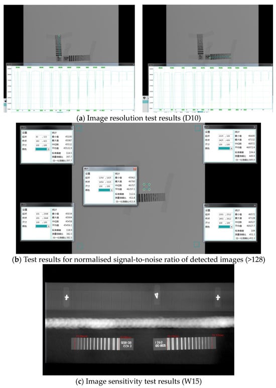
Figure 24.
Detect image quality.
5.3. Comparison Test Between Digital Radiography and Film Radiography
Digital radiographic imaging inspection (DR) and film radiographic inspection (RT) were performed on typical products. The inspection efficiency, calculated in person-minutes, increased by more than five times compared to the values shown in Table 3. The single inspection cycle time (the time from the completion of image acquisition for the previous image to the completion of image acquisition for the next image) was approximately 20 s. As shown in Table 4, the products to be tested were inspected using the digital radiographic imaging inspection method (DR) and film radiographic inspection method (RT) with this system, and the inspection results were compared. The results obtained using the digital radiographic imaging inspection method and the film radiographic inspection method were consistent. Additionally, the image quality of the digital radiographic imaging inspection method (DR) was superior to that of the film radiographic inspection method (RT), with the image quality being one order of magnitude higher. Partial defect images from the two inspection methods are shown in Figure 25, Figure 26 and Figure 27.

Table 3.
Comparison of Inspection Efficiency.

Table 4.
Comparison of test results for detection images.

Figure 25.
Comparison of inspection results for unmerged welds on cylinder segments.

Figure 26.
Comparison of tungsten-included defects in the longitudinal seam of the ring section.

Figure 27.
Comparison of Arc Weld Defects in Cracked Box Bottoms.
6. Conclusions
(1) To enhance the efficiency and accuracy of radiographic testing for rocket tank welds, a dual-robot collaborative digital radiographic inspection system was designed, tailored to the structural characteristics of rocket tank welds. The control system employs a Beckhoff controller communicating with robots and servo motors via the EtherCAT protocol. The X-ray machine controller and imaging inspection software utilize the ADS multithreaded communication protocol. This integrates the operation of the X-ray machine controller, imaging inspection software, lifting mechanism, and turntable with the robot body and seventh-axis movements. Through rational design of logical timing sequences, the system achieves an automated inspection process for rocket tank welds.
(2) A dual-robot collaborative inspection strategy with dual-mode switching is proposed. Corresponding mode switching rules are designed for critical points during the digital radiographic inspection of rocket tank welds by dual-robots. The dual-modes primarily encompass loose coordination and tight coordination with full constraints. During loose coordination, collision and interference issues are primarily addressed, mainly utilizing an improved artificial potential field method for dual-robot path planning. In tight coordination with full constraints, detection consistency issues are primarily considered, establishing relevant constraints based on the digital radiography process. Finally, the robot detection paths generated by the dual modes are combined to complete the dual-robot detection path trajectory planning.
(3) An imaging software platform was designed integrating VS and Twincat software with a QT-based host computer interface. This platform encompasses functional modules for detector control, X-ray machine control, mechanical motion control, image acquisition, image processing, and information display. Ultimately, it forms an intelligent imaging software platform integrating imaging, image processing, and mechanical motion for unified detection and control.
(4) The designed dual-robot collaborative digital radiographic inspection system for rocket tank welds was applied to inspect typical components including arc welds, circumferential welds, longitudinal welds on cylindrical sections, and butt welds on half-tanks. Compared to existing traditional radiographic methods, this system achieves a 5-fold increase in inspection efficiency, achieving image sensitivity of W14, resolution of D10, and a standardized signal-to-noise ratio of 128. These metrics significantly exceed Grade A process requirements and fully meet current non-destructive testing demands for multi-model rocket tank welds.
7. Discussion and Future Work
This paper integrates dual-robot control technology with digital X-ray inspection technology to develop a dual-robot collaborative digital X-ray inspection system for detecting internal defects in rocket tank welds. This system can be directly applied to digital radiographic inspection of welds on the bottoms, cylindrical sections, and short shells of multiple rocket tank models. However, the following limitations remain: robotic errors and manual setting of digital radiographic inspection parameters constrain further improvements in inspection accuracy, while weld defect identification still relies on manual evaluation, further impacting inspection time and accuracy. Future research will focus on three key directions: (1) enhancing the precision of inspection actuators through robotic error compensation methods to ensure image consistency; (2) developing neural network models for adaptive adjustment of digital radiography parameters; (3) integrating deep learning technology to achieve automated weld defect recognition, balancing efficiency and accuracy in radiographic image analysis to enable precise and rapid defect detection during rocket tank manufacturing.
Author Contributions
Writing—original draft, G.L. and C.S.; Validation, Z.W. and K.D.; Writing—review and editing, Y.L. and D.G. All authors have read and agreed to the published version of the manuscript.
Funding
This work was supported by the National Natural Science Foundation of China (Nos. 52405464 and 52475441), the Postdoctoral Fellowship Program of CPSF under Grant Number GZB20240958, the Heilongjiang Provincial Postdoctoral Science Foundation (LBH-Z24132), and the Fundamental Research Funds for the Central Universities.
Institutional Review Board Statement
Not applicable.
Informed Consent Statement
Not applicable.
Data Availability Statement
The data is included in the article.
Conflicts of Interest
The authors declare no conflict of interest.
References
- Anandan, B.; Manikandan, M. Effect of welding speeds on the metallurgical and mechanical property characterization of friction stir welding between dissimilar aerospace grade 7050 T7651-2014A T6 aluminium alloys. Mater. Today Commun. 2023, 35, 106246. [Google Scholar] [CrossRef]
- Wang, G.; Zhao, Y.; Hao, Y. Friction stir welding of high-strength aerospace aluminum alloy and application in rocket tank manufacturing. J. Mater. Sci. Technol. 2018, 34, 73–91. [Google Scholar] [CrossRef]
- Mishra, R.S.; Ma, Z.Y. Friction stir welding and processing. Mater. Sci. Eng. R Rep. 2005, 50, 1–78. [Google Scholar] [CrossRef]
- Li, S.; Yue, X.; Li, Q.; Peng, H.; Dong, B.; Liu, T.; Yang, H.; Fan, J.; Shu, S.; Qiu, F.; et al. Development and applications of aluminum alloys for aerospace industry. J. Mater. Res. Technol. 2023, 27, 944–983. [Google Scholar] [CrossRef]
- Heinz, A.; Haszler, A.; Keidel, C.; Moldenhauer, S.; Benedictus, R.; Miller, W.S. Recent development in aluminium alloys for aerospace applications. Mater. Sci. Eng. A 2000, 280, 102–107. [Google Scholar] [CrossRef]
- Zhang, M.; Yu, X.; Lu, H.; Wu, Y.; Guo, P.; Lian, G. Deep transfer learning + BDENet: An innovative approach for detecting the internal defects of weld seams using radiographic imaging. Int. J. Press. Vessel. Pip. 2025, 215, 105467. [Google Scholar] [CrossRef]
- Shen, M.; Yang, J.; Jiang, W.; Wang, Y. A physics-guided memory-enhanced semi-supervised approach for detecting weld defects in radiographic images. NDT E Int. 2025, 157, 103521. [Google Scholar] [CrossRef]
- Wu, Y.; Yang, G.; Sun, J.; Cui, L.; Wang, M. Digital twin modeling and leak diagnosis of temperature and stress fields in LNG storage tanks. Measurement 2024, 228, 114374. [Google Scholar] [CrossRef]
- Li, Y.; Oyang, D.; Song, M.; Shi, H. The response characteristics and damage effects of large LNG storage tanks subject to the coupled effects of explosion shock waves and fire. Nat. Gas Ind. B 2024, 11, 303–315. [Google Scholar] [CrossRef]
- Mo, L.; Wang, R.; Yang, H.; Yang, Y.; Wu, X.; Jia, W.; Li, C.; Chen, C. Dynamic response of spherical tanks subjected to the explosion of hydrogen-blended natural gas. Fuel 2024, 377, 132834. [Google Scholar] [CrossRef]
- Zhu, F.; Bai, X.; Xia, Z.; Meng, T.; Liu, X.; Yin, W.; Yang, W. Pose control and profile tracking with eddy current sensor and robotic arm for NDT applications. NDT E Int. 2025, 151, 103312. [Google Scholar] [CrossRef]
- Ou, Y.; Xu, T.; Fan, J.; Xu, B.; Cai, H.; Zhao, J. Vision-based quality evaluation method towards automated penetrant testing. NDT E Int. 2025, 153, 103334. [Google Scholar] [CrossRef]
- Li, J.; Tong, T.; Yuan, X.; Ma, Y.; Zhao, D.; Zhou, X.; Liu, P.; Zhang, J. Automated system and adaptive pixel-wise detection network for intelligent diagnosis of turbine blade defects. Mech. Syst. Signal Process. 2025, 237, 113133. [Google Scholar] [CrossRef]
- Xiong, Z.; Chen, Y.; Cheng, Y.; Lu, C.; Jin, S. Free tool central point total focusing method for imaging large-size curved components under robotic automation ultrasonic testing. Measurement 2025, 256, 118493. [Google Scholar] [CrossRef]
- Liu, Z.; Riaz, W.; Shen, Y.; Wang, X.; He, C.; Shen, G. Magneto acoustic emission technique: A review of methodology, applications, and future prospects in non-destructive testing. NDT E Int. 2024, 146, 103171. [Google Scholar] [CrossRef]
- Cherfaoui, M. Innovative techniques in non-destructive testing and industrial applications on pressure equipment. Procedia Eng. 2012, 46, 266–278. [Google Scholar] [CrossRef]
- Hassan, I.U.; Panduru, K.; Walsh, J. Non-destructive testing methods for condition monitoring: A review of techniques and tools. Procedia Comput. Sci. 2025, 257, 420–427. [Google Scholar] [CrossRef]
- Silva, M.I.; Malitckii, E.; Santos, T.G.; Vilaça, P. Review of conventional and advanced non-destructive testing techniques for detection and characterization of small-scale defects. Prog. Mater. Sci. 2023, 138, 101155. [Google Scholar] [CrossRef]
- Waqar, M.; Memon, A.M.; Sabih, M.; Alhems, L.M. Composite pipelines: Analyzing defects and advancements in non-destructive testing techniques. Eng. Fail. Anal. 2024, 157, 107914. [Google Scholar] [CrossRef]
- Park, B.; Lee, S.; Lee, E.; Kim, M.; Seo, H. Method for determining primary radiation shielding thickness of industrial X-ray-generating devices. Appl. Radiat. Isot. 2025, 222, 111862. [Google Scholar] [CrossRef]
- Schuetz, P.; Miceli, A.; Jerjen, I.; Flisch, A.; Hofmann, J.; Broennimann, R.; Sennhauser, U. Reducing environmental scattering in industrial computed tomography by system redesign. NDT E Int. 2013, 58, 36–42. [Google Scholar] [CrossRef]
- Shraddha, C.; Priyadarshi, P.; Ghate, D.P. A survey of launch vehicle recovery techniques. Prog. Aerosp. Sci. 2025, 155, 101092. [Google Scholar] [CrossRef]
- Song, Z.; Xie, Z.; Qiu, L.; Xiang, D.; Li, J. Prospects of sea launches for Chinese cryogenic liquid-fueled medium-lift launch vehicles. Chin. J. Aeronaut. 2021, 34, 424–437. [Google Scholar] [CrossRef]
- Wagenblast, B.N.; Bettinger, R.A. Statistical reliability estimation of space launch vehicles: 2000–2022. J. Space Saf. Eng. 2024, 11, 573–589. [Google Scholar] [CrossRef]
- Liu, T.; Zheng, H.; Zheng, P.; Bao, J.; Wang, J.; Liu, X.; Yang, C. An expert knowledge-empowered CNN approach for welding radiographic image recognition. Adv. Eng. Inform. 2023, 56, 101963. [Google Scholar] [CrossRef]
- Pasupulla, A.P.; Agisho, H.A.; Seetharaman, S.; Vijayakumar, S. Characterization and analysis of TIG welded stainless steel 304 alloy plates using radiography and destructive testing techniques. Mater. Today Proc. 2022, 51, 935–938. [Google Scholar] [CrossRef]
- Liu, T.; Zheng, P.; Bao, J.; Chen, H. A state-of-the-art survey of welding radiographic image analysis: Challenges, technologies and applications. Measurement 2023, 214, 112821. [Google Scholar] [CrossRef]
- Wang, P.; Li, L.; Li, X.; Duan, L.; Lü, Z.; Di, R. An automatic welding defect detection method based on deep learning for super 8-bit high grayscale X-ray films of solid rocket motor shells. NDT E Int. 2025, 151, 103306. [Google Scholar] [CrossRef]
- Lu, S.; Wang, J.; Cheng, L.; Duan, Y.; Zhao, Y.; Lin, C.; Li, J.; Zhan, X. Unraveling stress inheritance and distribution mechanisms in the multi-stage processing of 2219 aluminum alloy tanks. CIRP J. Manuf. Sci. Technol. 2025, 61, 524–541. [Google Scholar] [CrossRef]
- Chen, L.; Li, B.; Zhang, L.; Shang, Z. 3D positioning of defects for gas turbine blades based on digital radiographic projective imaging. NDT E Int. 2023, 133, 102751. [Google Scholar] [CrossRef]
- Casalta, S.; Daquino, G.G.; Metten, L.; Oudaert, J.; Van de Sande, A. Digital image analysis of X-ray and neutron radiography for the inspection and the monitoring of nuclear materials. NDT E Int. 2003, 36, 349–355. [Google Scholar] [CrossRef]
- Yin, Y.; Gao, D.; Lu, Y.; Zhao, C.; Li, G.; Deng, K. In-situ robot joint stiffness identification using an eye-in-hand camera with optimal measurement pose selection. Measurement 2025, 253, 117579. [Google Scholar] [CrossRef]
- Bilancia, P.; Locatelli, A.; Tutarini, A.; Mucciarini, M.; Iori, M.; Pellicciari, M. Online motion accuracy compensation of industrial servomechanisms using machine learning approaches. Robot. Comput.-Integr. Manuf. 2025, 91, 102838. [Google Scholar] [CrossRef]
- Chen, H.; Yang, J.; Ding, H. Robotic compliant grinding of curved parts based on a designed active force-controlled end-effector with optimized series elastic component. Robot. Comput. Manuf. 2024, 86, 102646. [Google Scholar] [CrossRef]
- Zhang, T.; Peng, F.; Yan, R.; Tang, X.; Deng, R.; Yuan, J. Quantification of uncertainty in robot pose errors and calibration of reliable compensation values. Robot. Comput.-Integr. Manuf. 2024, 89, 102765. [Google Scholar] [CrossRef]
- Ryzhykov, V.D.; Lysetska, O.K.; Opolonin, O.D.; Kozin, D. X-ray radiation detectors of “scintillator-photoreceiving device type” for industrial digital radiography with improved spatial resolution. Nucl. Instrum. Methods Phys. Res. Sect. A Accel. Spectrom. Detect. Assoc. Equip. 2003, 505, 544–548. [Google Scholar] [CrossRef]
- Zhang, X.; Tang, Z.; Wei, Q.; Wang, A.; Wang, M.; Sun, H.; Wu, Y.; Xia, C.; Qian, M.; Wang, H.; et al. High-throughput screening of process parameters and composition in laser additive manufacturing via in-situ X-ray imaging. Scr. Mater. 2025, 263, 116681. [Google Scholar] [CrossRef]
- Amersdorfer, M.; Kappey, J.; Meurer, T. Real-time freeform surface and path tracking for force controlled robotic tooling applications. Robot. Comput. Manuf. 2020, 65, 101955. [Google Scholar] [CrossRef]
Disclaimer/Publisher’s Note: The statements, opinions and data contained in all publications are solely those of the individual author(s) and contributor(s) and not of MDPI and/or the editor(s). MDPI and/or the editor(s) disclaim responsibility for any injury to people or property resulting from any ideas, methods, instructions or products referred to in the content. |
© 2025 by the authors. Published by MDPI on behalf of the International Institute of Knowledge Innovation and Invention. Licensee MDPI, Basel, Switzerland. This article is an open access article distributed under the terms and conditions of the Creative Commons Attribution (CC BY) license (https://creativecommons.org/licenses/by/4.0/).