Article

Experimental and Numerical Validation of an Extended FFR Model for Out-of-Plane Vibrations in Discontinuous Flexible Structures

by
Sherif M. Koda
1,2,*,
Masami Matsubara
3,
Ahmed M. R. Fath El-Bab
1 and
Ayman A. Nada
1,*
1
Department of Mechatronics and Robotics Engineering, School of Innovative Design Engineering, Egypt-Japan University of Science and Technology E-JUST, New Borg El-Arab, Alexandria 21934, Egypt
2
Department of Mechanical Engineering, Benha Faculty of Engineering, Benha University, Benha 13518, Egypt
3
Department of Modern Mechanical Engineering, Faculty of Science and Engineering, Waseda University, Tokyo 169-8555, Japan
*
Authors to whom correspondence should be addressed.
Appl. Syst. Innov. 2025, 8(5), 118; https://doi.org/10.3390/asi8050118
Submission received: 5 July 2025 / Revised: 13 August 2025 / Accepted: 19 August 2025 / Published: 22 August 2025
(This article belongs to the Section Control and Systems Engineering)

Abstract

Toward the innovative design of tunable structures for energy generation, this paper presents an extended Floating Frame of Reference (FFR) formulation capable of modeling slope discontinuities in flexible multibody systems—overcoming a key limitation of conventional FFR methods that assume slope continuity. The model is validated using a spatial double-pendulum structure composed of circular beam elements, representative of out-of-plane energy harvesting systems. To investigate the influence of boundary constraints on dynamic behavior, three electromagnetic clamping configurations—Fixed–Free–Free (XFF), Fixed–Free–Fixed (XFX), and Free–Fixed–Free (FXF)—are implemented. Tri-axial accelerometer measurements are analyzed via Fast Fourier Transform (FFT), revealing natural frequencies spanning from 38.87 Hz (lower frequency range) to 149.01 Hz (higher frequency range). For the lower frequency range, the FFR results (38.76 Hz) show a close match with the experimental prediction (38.87 Hz) and ANSYS simulation (36.49 Hz), yielding 0.28% error between FFR and experiments and 5.85% between FFR and ANSYS. For the higher frequency range, the FFR model (148.17 Hz) achieves 0.56% error with experiments (149.01 Hz) and 0.85% with ANSYS (146.91 Hz). These high correlation percentages validate the robustness and accuracy of the proposed FFR formulation. The study further shows that altering boundary conditions enables effective frequency tuning in discontinuous structures—an essential feature for the optimization of application-specific systems such as wave energy converters. This validated framework offers a versatile and reliable tool for the design of vibration-sensitive devices with geometric discontinuities.

1. Introduction

The analysis of Flexible Multibody Systems (FMBSs) is crucial across various engineering disciplines, including aerospace, automotive, robotics, biomechanics, and renewable energy, due to their widespread applications. These systems consist of interconnected rigid and flexible components that undergo large overall motions while experiencing small to large elastic deformations. The accurate modeling of FMBSs is essential for understanding their dynamic behavior, optimizing performance, and ensuring structural integrity under varying operating conditions [1,2,3,4,5,6]. Two dominant methodologies exist for FMBS modeling: the Absolute Nodal Coordinate Formulation (ANCF) [7,8], which excels in capturing large nonlinear deformations, and the Floating Frame of Reference (FFR) formulation [9,10], renowned for its computational efficiency in systems with small deformations superimposed on large motions.
While FFR is widely adopted for its balance of accuracy and efficiency, existing implementations assume slope continuity along flexible components—a limitation that restricts its application to structures with inherent geometric discontinuities, such as joints, cracks, or segmented energy harvesters. This gap is critical in applications like vibration-based energy harvesting, where directional sensitivity and structural complexity often necessitate discontinuous modeling. Although model order reduction techniques [11] have enhanced FFR’s computational appeal, no prior work has extended FFR to explicitly address slope discontinuities while retaining its efficiency advantages.
The ANCF employs global position and gradient coordinates within a finite element framework, enabling the accurate representation of large deformations and nonlinear behaviors. In contrast, the FFR formulation assumes small elastic deformations superimposed on large rigid-body motions, making it computationally efficient and especially suitable for systems with moving bases such as robotic arms, aerospace structures, and vehicle suspensions [2,9,10]. FFR’s efficiency stems from its linearization of elastic deformation and its ability to capture dynamic coupling through joint constraints [12]. Recent developments have further enhanced FFR’s applicability by improving its implementation in solid finite elements and enabling coordinate transformations for complex interface conditions [13].
However, extending the FFR formulation to accommodate large deformations presents significant challenges due to its foundational assumption of small strains. Research has been conducted to modify and enhance the FFR approach for large deformation scenarios. For example, Nada et al. [9] explored the application of the FFR formulation in large deformation analysis, providing both experimental and numerical validation of its capabilities in such contexts. Figure 1 illustrates various applications of the FFR formulation, where the motion is defined by significant rigid body movement combined with minor elastic deformation. Furthermore, a new FFR formulation has been proposed that improves its applicability to flexible multibody systems by developing coordinate transformations that express absolute floating frame coordinates and local generalized coordinates in terms of absolute interface coordinates [13].
These advancements contribute to making FFR more versatile for complex engineering applications. For instance, graded elastic metasurfaces have been developed to enhance vibration-based energy harvesting by manipulating wave propagation characteristics [14]. L-shaped beam structures have also been explored for low-frequency broadband energy harvesting, capitalizing on geometric nonlinearities to improve bandwidth and efficiency [15]. Additionally, MEMS-based electrothermal mirrors integrated with multibody structures have been used for precise dynamic control in spectrometry applications [16], and piezoelectric harvesting strategies targeting ambient vibrations and acoustic waves have been reviewed to support smart structural applications [17].
Despite these advancements, conventional FFR formulations are generally limited to modeling continuous flexible bodies and often assume slope continuity along the structure. This assumption restricts their application to configurations involving geometric discontinuities, such as sudden changes in cross-section or connected segments with angular offsets. Addressing this limitation is crucial for extending the applicability of FFR to a broader class of engineering systems, particularly those that exhibit spatial double slope discontinuities under dynamic loading. In this context, Bishiri and Nada [18] proposed a semi-continuum multibody modeling framework using the Absolute Nodal Coordinate Formulation (ANCF), which effectively captures slope discontinuities and restricted deformations by employing simplified strain tensors and locally linear stiffness matrices. Their approach was experimentally validated through operational modal analysis of a spatial double pendulum, demonstrating strong agreement between theoretical predictions and measured frequencies. While their work highlights the robustness of ANCF for modeling structural discontinuities, the present study extends these modeling capabilities to the FFR formulation—offering a more computationally efficient alternative for systems dominated by rigid body motion and small to moderate elastic deformation.
The need for more flexible modeling strategies is particularly pronounced in marine energy systems, where flexible structures are frequently integrated with floating or modular platforms. For example, Heo et al. [19] investigated ocean wave energy conversion using flexible structural elements, demonstrating the importance of accurately modeling the interactions between fluid forces and structural deformation. Similarly, Park et al. [20] performed a multibody dynamic analysis of wave energy converters mounted on floating platforms, emphasizing the significance of capturing interactions between moving bases and attached flexible components. Recent studies on modular floating structures that integrate artificial reefs and wave energy converters [21], as well as analyses of the hydrodynamic characteristics of offshore floating photovoltaic platforms [22], further highlight the complex dynamic behavior of marine renewable energy systems. These works collectively underscore the limitations of traditional modeling assumptions—such as slope continuity—and motivate the need for advanced formulations capable of handling structural discontinuities while maintaining computational efficiency.
Additionally, Nada et al. [10] conducted a comparative experimental and numerical study on the use of FFR and ANCF in large deformation analysis of robotic manipulators, highlighting the strengths and limitations of each approach. These studies indicate that while the FFR formulation offers computational efficiency for systems with predominantly rigid-body motion and small elastic deformations, modifications to its theoretical framework can extend its applicability to large deformation problems, enhancing its utility in fields such as robotics, aerospace, structural engineering, and renewable energy.
In recent years, the integration of multiple modeling paradigms and data-driven techniques has gained traction in the field of flexible multibody dynamics. For instance, Ling et al. [23] proposed a hybrid modeling framework that combines the Absolute Nodal Coordinate Formulation (ANCF) and the Floating Frame of Reference (FFR) approach to simulate flexible beams undergoing large rotations, offering enhanced accuracy in representing structural deformation and inertial coupling. In parallel, machine learning–based techniques have emerged as powerful tools for model reduction and dynamic approximation. Tomas et al. [24] introduced a machine learning approach for simulating flexible body dynamics, effectively replacing the traditional solution of differential equations with trained surrogate models. Similarly, Angeli et al. [25] developed a deep learning framework using physics-informed autoencoders to perform model order reduction for multibody systems, enabling real-time prediction of dynamic responses with reduced computational cost. While these hybrid and ML-based approaches offer promising directions, the present work focuses on improving the classical FFR formulation to account for slope discontinuities in spatial flexible multibody systems, providing a robust yet computationally efficient alternative that remains fully interpretable and physically grounded.
In this study, an enhanced FFR-based modeling approach is developed to incorporate slope discontinuities within flexible multibody systems. The methodology is applied to a spatial double-pendulum structure composed of 3D beam elements with circular cross-sections, serving as a representative configuration for out-of-plane energy harvesting. Experimental validation is performed using a custom-built test rig subjected to three distinct boundary conditions, with natural frequencies extracted from vibration response data. Commercial FEM tools such as ANSYS [26] are widely used for structural simulations due to their robust element libraries and solver capabilities. The theoretical predictions obtained from the proposed FFR model are further compared against finite element simulations conducted in ANSYS. The results demonstrate strong agreement across all methods, confirming the effectiveness of the extended FFR formulation in capturing the dynamic behavior of structures with geometric discontinuities. The validated frequency range, spanning from 38.87 Hz to 149.01 Hz, highlights the model’s suitability for vibration-based energy harvesting applications involving complex spatial geometries and boundary condition variability.
To facilitate a comprehensive understanding of the proposed modeling approach, the remainder of this paper is organized as follows. Section 1 introduces the background of flexible multibody dynamics, contrasts the FFR formulation with the ANCF, and outlines the motivation for extending FFR to handle slope discontinuities. Section 2 presents the theoretical formulation of the proposed FFR-based approach, including the procedure for incorporating slope discontinuities through modifications to the connectivity matrix. Section 3 describes the experimental setup, detailing the construction of a spatial double-pendulum structure using 3D beam elements with circular cross-sections, and outlines the testing under three different boundary conditions using a custom-built vibration test rig. Theoretical results from the extended FFR model are then compared with both experimental data and finite element simulations conducted in ANSYS. Finally, Section 4 summarizes the key findings, discusses the applicability of the proposed approach to vibration-based energy harvesting systems, and outlines directions for future research.
The primary objectives of this study are to develop an extended Floating Frame of Reference (FFR) formulation that accurately captures slope discontinuities in flexible multibody systems, to experimentally validate this formulation using a spatial double-pendulum structure subjected to various boundary conditions, and to assess its predictive accuracy through comparison with ANSYS finite element simulations and measured vibration data. By achieving these aims, the study demonstrates the applicability of the proposed model to energy harvesting applications involving complex geometries and discontinuous structures, offering a computationally efficient yet robust alternative to existing methods.

2. Floating Frame of Reference Formulation

In the Floating Frame of Reference (FFR) approach, structural flexibility is defined in relation to a specific reference frame, which is used to account for large displacements and rotations. According to Shabana [3], the global position vector of any arbitrary point P i j on flexible body i within element j can be represented using this framework. This methodology has been widely adopted for its computational efficiency and suitability in systems where small elastic deformations are superimposed on large rigid body motions [9,27,28]. In particular, Wallrapp [28] provided a standardized modeling procedure for flexible bodies in multibody system codes, which remains influential in current simulation platforms.
r i j = R i + A i u ¯ i j
The vector R i specifies the position of the origin of the body-fixed coordinate system x i y i z i , which corresponds to the floating frame. The matrix A i represents the transformation matrix that describes the orientation of the floating frame x i y i z i relative to the inertial frame X Y Z , depending on the orientation parameters θ i . Additionally, the vector u ¯ i j denotes the position of the point P i j in relation to the body-fixed coordinate system; see Figure 2. The vector u ¯ i j can be described in terms of elastic coordinates as:
( u ¯ i j ) = ( u ¯ i j , 0 ) + ( u ¯ i j , f ) = ( u ¯ i j , 0 ) + S i j X 0 i j ( q i j , f )
The ( u ¯ i j , 0 ) represents the position of point P in its undeformed state and is expressed as ( u ¯ i j , 0 ) = ( x i j , p ) ( y i j , p ) ( z i j , p ) T . Meanwhile, ( u ¯ i j , f ) captures the elastic deformation of the element in the body coordinate system and is defined by ( u ¯ i j , f ) = S i j X 0 i j ( q i j , f ) . Here, S i j X 0 i j is the shape matrix, which varies spatially along and within the element, and ( q i j , f ) is the temporal vector containing the elastic nodal coordinates of element j in the local coordinate system of body i. When the body is divided into n elements, the global position vector r i j is expressed as:
r i j = R i + A i ( u ¯ i j , 0 ) + A i j S i j B 1 i j B 2 i ( q i , f )
The matrix B 1 i j represents the connectivity matrix, while B 2 i serves as the linear-transformation matrix responsible for enforcing the boundary conditions of the element. In this context, ( q i , f ) denotes the unconstrained vector of nodal coordinates for body i, which can be interpreted as the generalized elastic coordinates of the flexible body. The ( q i , f ) vector has dimensions D O F s i × 1 , where D O F s i represents the total elastic degrees of freedom associated with the i t h flexible body.
The matrix M f f i is a summation of elementary mass mtrices M f f i j = V i j [ S i j ] T S i j d V i j for n e finite elements and can be written as:
M f f i = B 2 i T j = 1 n e B 1 i j T M f f i j B 1 i j B 2 i
The stiffness matrix can be written as:
K f f i = B 2 i T j = 1 n e B 1 i j T K f f i j B 1 i j B 2 i
The stiffness matrix of the element K f f i j is a constant matrix that appears in linear structural systems.

Slope Discontinuity

The FFR formulation is a powerful tool in the analysis of flexible multibody systems, particularly for applications involving large rigid body motions superimposed with small elastic deformations. A critical challenge within this framework arises when slope discontinuities occur in the system. Slope discontinuities, which represent abrupt changes in the deformation gradient, are typically encountered at geometric irregularities, joints, or locations where material properties vary significantly. These discontinuities pose significant challenges for accurately modeling the elastic behavior and ensuring numerical stability in the equations of motion [29].
In finite element models, the continuity of deformation and its derivatives is governed by the shape functions used. Lower-order shape functions, while computationally efficient, often fail to capture the effects of discontinuities, resulting in inaccuracies in strain and stress calculations [3]. Furthermore, concentrated loads, boundary conditions, and abrupt transitions between elements exacerbate these challenges by introducing localized changes in the slope of the deformation.
To mitigate these issues, various approaches have been proposed. Refining the finite element mesh near regions of discontinuity and employing higher-order shape functions have proven effective in capturing slope changes more accurately [30]. Additionally, hybrid techniques that combine the FFR formulation with advanced modeling methods, such as ANCF, offer improved performance in handling discontinuities in elastic systems [4].
Addressing slope discontinuities is essential for preserving the accuracy and reliability of the FFR formulation, particularly in complex systems where the elastic behavior significantly influences the dynamic response. This paper explores strategies to model slope discontinuities effectively and discusses their implications on the dynamic analysis of flexible multibody systems.
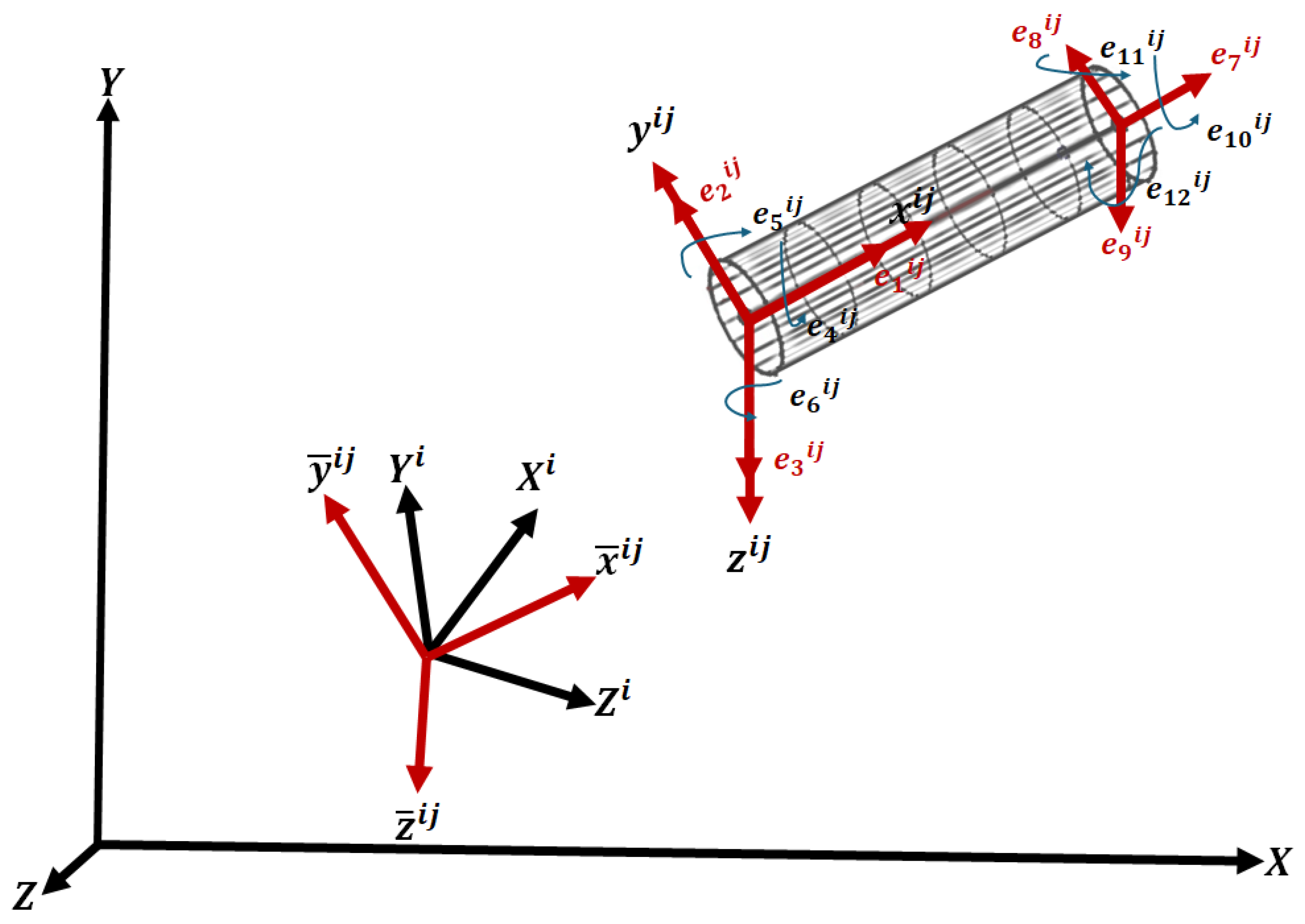
Figure 3 illustrates a three-dimensional beam element j belonging to body i. This element is characterized by 12 nodal coordinates, which define the translations and slopes at its two nodes. These nodal coordinates, referenced with respect to the local coordinate system x ¯ i j y ¯ i j z ¯ i j , are represented by the vector e ¯ i j , which is:
e ¯ i j = e ¯ 1 i j e ¯ 2 i j e ¯ 12 i j T
The position of the origin of the ith body reference frame relative to the inertial frame is described by the Cartesian coordinates R i . An arbitrary point P i j on element i j is located by the vector w i i j = w 1 i j w 2 i j w 3 i j T , which is defined with respect to the local coordinate system x ¯ i j y ¯ i j z ¯ i j . Here, w 1 i j , w 2 i j , and w 3 i j represent the components of w i i j along x ¯ i j y ¯ i j z ¯ i j , respectively. So, u ¯ i j can be expressed as:
u ¯ i j = C i j S i j C ¯ i j e i j
Here, e i j represents the nodal coordinate vector of element i j , defined with respect to the body coordinate system.
To transform coordinates from the element coordinate system to the body coordinate system, the rotation matrix C i j is utilized. The direction cosines for the axes x ¯ i j y ¯ i j z ¯ i j can be determined directly through geometric considerations. Alternatively, these can be derived using a stepwise rotation of axes. Let ( K 1 , K 2 , K 3 ) and ( G 1 , G 2 , G 3 ) represent the positions of the nodes of element i j . The transformation matrix mapping the element axes to the body axes is given as described by [31]:
C i j = c x c x c y ( c x ) 2 + ( c z ) 2 c z ( c x ) 2 + ( c z ) 2 c y ( c x ) 2 + ( c z ) 2 0 c z c y c z ( c x ) 2 + ( c z ) 2 c x ( c x ) 2 + ( c z ) 2 i j
where c x i j = G 1 K 1 L i j , c y i j = G 2 K 2 L i j , c z i j = G 3 K 3 L i j , and L i j is the length of the element, which is defined as:   
L i j = ( G 1 K 1 ) 2 + ( G 2 K 2 ) 2 + ( G 3 K 3 ) 2
The orthogonality of the matrix i j can be confirmed, and this characteristic plays a crucial role throughout this analysis. This matrix remains applicable for all possible positions of the element, with the exception of the case where the element’s y i j axis aligns with the body’s Y i axis. In such a scenario, the transformation matrix C i j takes the form [31]:
C i j = 0 c y 0 c y 0 0 0 0 1 i j
When the rotations at the nodes relative to the body axes are infinitesimally small, the same matrix C i j from Equations (8) and (10) can be utilized to convert rotations from the element’s i j axes to the i-th body coordinate system. In other words, the matrix C ¯ i j is expressed as:
C ¯ i j = C i j 0 0 0 0 C i j 0 0 0 0 C i j 0 0 0 0 C i j T
Equations (3)–(5) have been revised to incorporate the effects of a discontinuous slope. These update accounts for the abrupt variations in the slope, ensuring that the mathematical model precisely captures the behavior across discontinuities. The revised equation introduces necessary adjustments to better represent the discontinuous characteristics of the slope, as expressed below:
r i j = R i + A i N i j q n i = R i + A i N i j ( q 0 i + B 2 i q f i )
where N i j represents the shape matrix, as shown in Figure 3, defined between elements i and j and between elements j and K. The shape matrix is expressed as:
N i j = C i j S i j C ¯ i j B 1 i j = C i j S i j B D 1 i j
where B D 1 i j represents the modified connectivity matrix specifically designed for continuous structures. After accounting for slope discontinuities, the updated mass matrix is given as:
M f D i = B 2 i T j = 1 n e B D 1 i j T M f f i j B D 1 i j B 2 i
where M f D i denotes the mass matrix for a structure with slope discontinuities. The stiffness matrix, updated to account for slope discontinuities, is expressed as:
K f D i = B 2 i T j = 1 n e B D 1 i j T K f f i j B D 1 i j B 2 i
where K f D i represents the stiffness matrix for a structure with slope discontinuities.
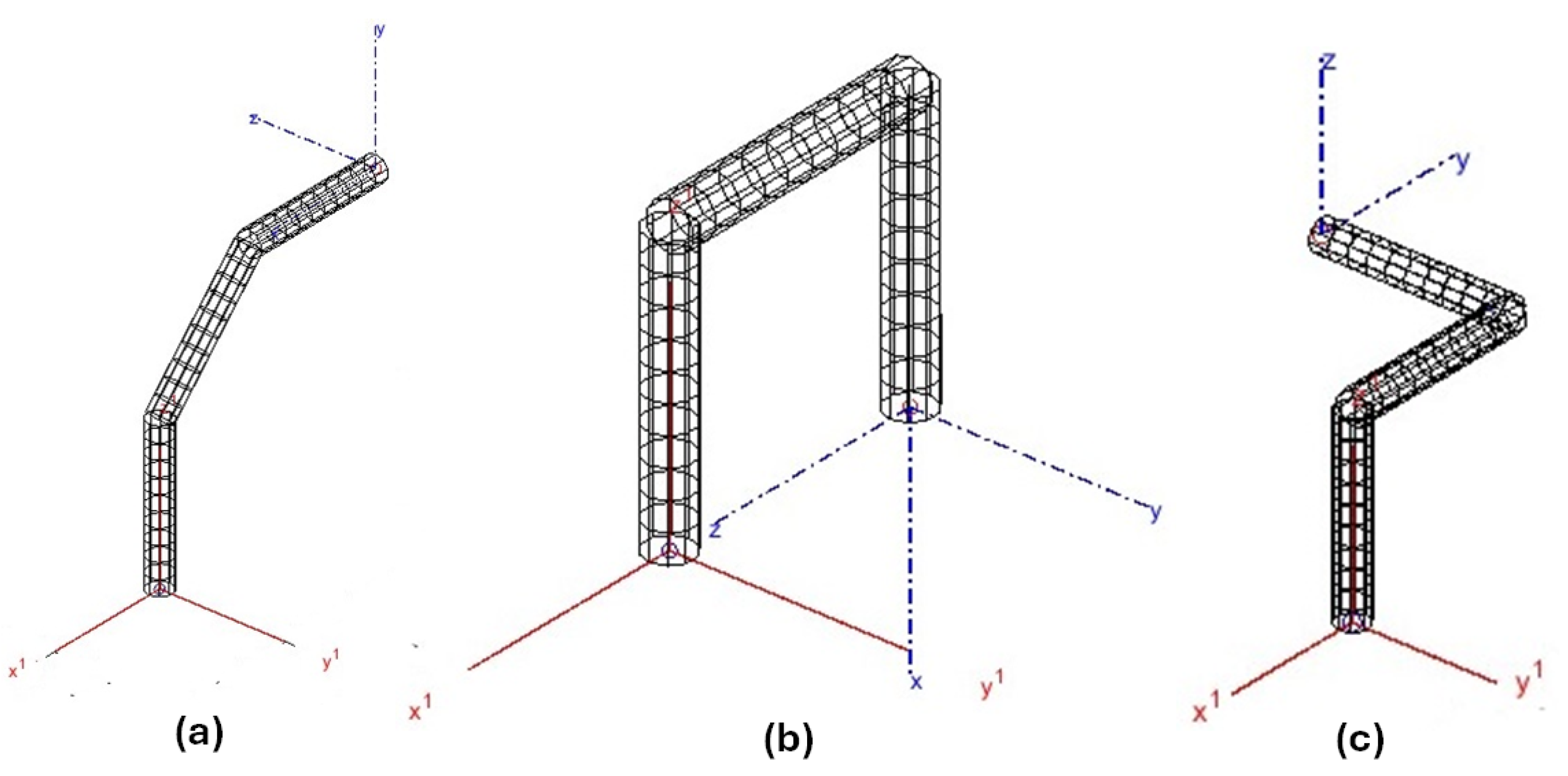
Several representative flexible structures exhibiting slope discontinuities are constructed, as shown in Figure 4. Each configuration consists of three connected segments, intentionally introducing angular offsets that result in sharp slope discontinuities. These structural configurations are designed to challenge the conventional assumptions of slope continuity typically adopted in the standard FFR formulation. By carefully defining the relative orientation between adjacent segments and enforcing geometric compatibility at their interfaces, the proposed modeling framework accommodates discontinuities while preserving the computational benefits of the FFR approach.

3. Experimental Study

A prototype of a spatial double-pendulum structure, shown in Figure 4c and Figure 5, is developed to experimentally validate the proposed FFR-based modeling approach for discontinuous flexible systems. The physical structure consists of three connected beam segments forming an L-shaped configuration, with each segment capable of undergoing deformation in different spatial planes. While the first segment primarily deforms in a fixed plane, the subsequent segments introduce additional degrees of freedom, leading to a complex and coupled dynamic response. This configuration serves as a representative model for discontinuous geometries and is particularly suitable for evaluating the directional sensitivity and modal characteristics of out-of-plane energy harvesters. Experimental modal analysis is conducted under three distinct boundary conditions, and the resulting natural frequencies are used to validate the theoretical predictions and finite element simulations.
The test specimen is composed of three-dimensional beam elements with circular cross-sections (8 mm in diameter) and an overall length of 450 mm, divided into three segments measuring 160 mm, 140 mm, and 150 mm, respectively. Sharp angular offsets at the segment junctions introduce deliberate slope discontinuities, making the structure well-suited for assessing the proposed extended FFR formulation. The structure is fabricated from plain carbon steel (mild steel), a commonly employed structural-grade material. The material properties used in the analysis are Young’s modulus ( E = 200  GPa), Poisson’s ratio of 0.29, and density of 7850 kg / m 3 . In designing the test specimen, the three bent segments were formed from a single continuous 450 mm rod without introducing any physical gaps between directional changes. This ensured geometric continuity across the structure, with the only discontinuities being angular (slope changes) at the bends. Consequently, the proposed FFR formulation in this study applies to systems exhibiting slope discontinuities without displacement discontinuities and does not model effects such as gaps, soft stops, or contact interactions.
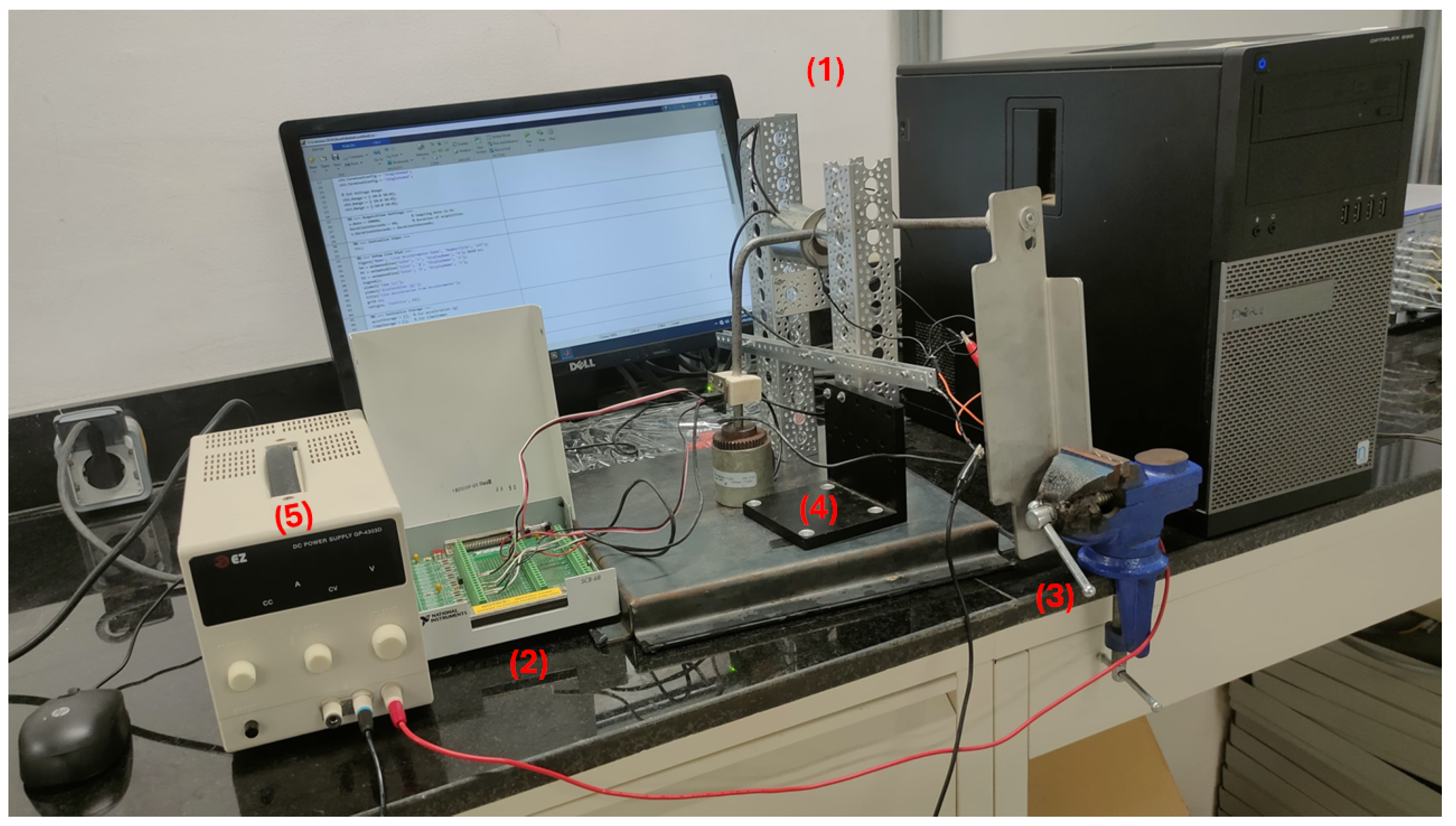
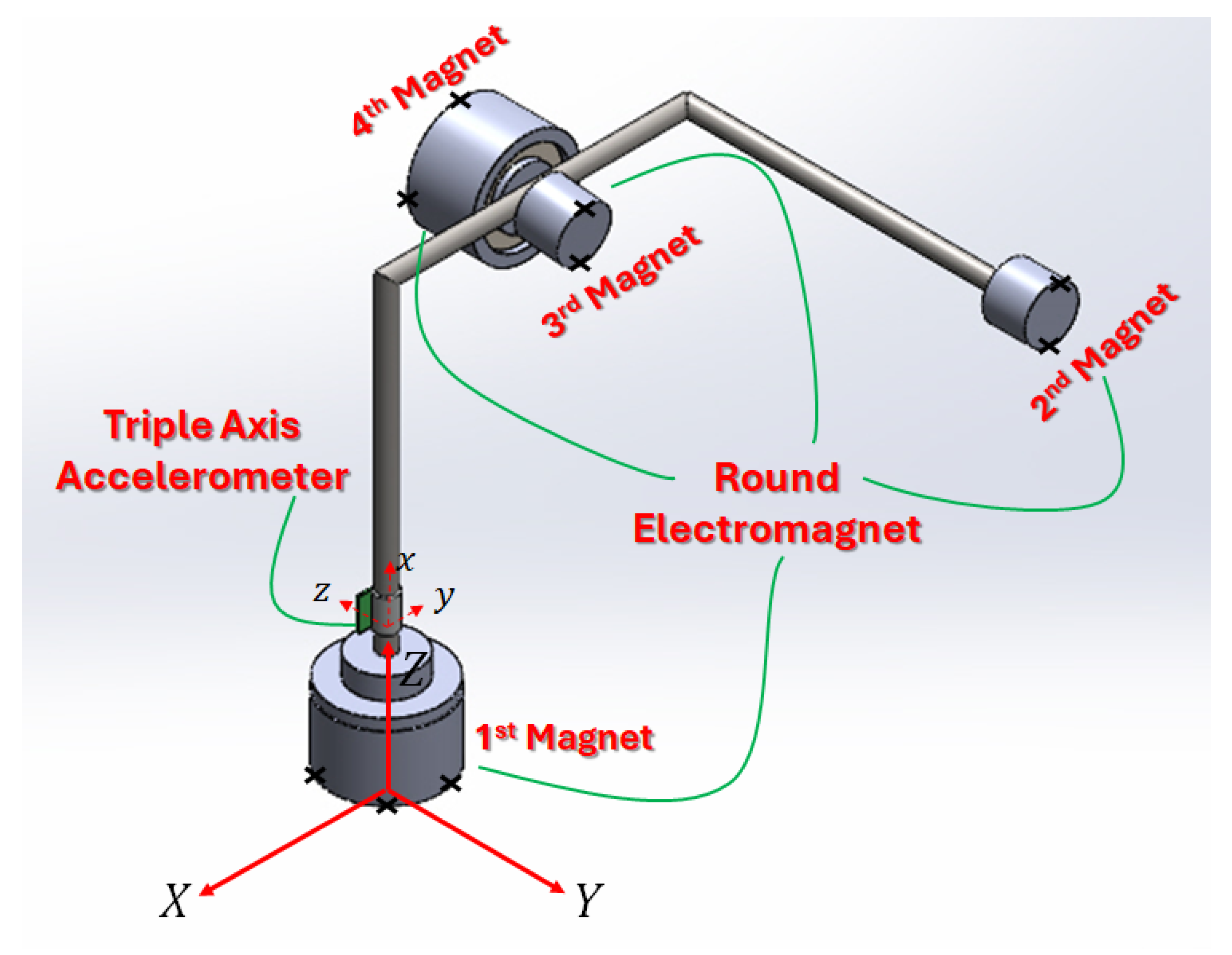
To realize the experimental validation of the proposed FFR formulation, a detailed test rig was developed. A rigid base plate was used to secure the first electromagnet, as illustrated in Figure 6, forming the fixed boundary for the XFF configuration. The remaining electromagnets were mounted on an aluminum frame using precision vice clamps, allowing reconfiguration to support XFX and FXF setups. Electromagnets were independently controlled via a programmable amplifier to switch between boundary configurations: activating only the first magnet for XFF, the first and second magnets for XFX, and only the third and fourth magnets for FXF. An impact hammer was used to excite the structure, while a tri-axial accelerometer captured the resulting vibrations. The signal from the accelerometer was processed using MATLAB R2024a to extract time- and frequency-domain characteristics, enabling accurate determination of the system’s natural frequencies for comparison with theoretical and finite element results.
In the FFR formulation, the boundary conditions of the flexible body, Equation (13), are enforced by modifying the system equations using constraint matrices, commonly denoted as B 2 i . This approach enables the application of various boundary condition configurations by appropriately constraining the system’s degrees of freedom. For example, under a Free–Free–Free (FFF) condition, the constraint matrix becomes an identity matrix, i.e., B 2 i = I 24 × 24 , indicating that no constraints are applied to the body.
In this study, three distinct boundary condition configurations are considered: Fixed–Free–Free (XFF), as defined in Equation (16a); Fixed–Free–Fixed (XFX), as defined in Equation (16b); and Free–Fixed–Free (FXF), as defined in Equation (16c). Each configuration requires a specifically tailored form of the B 2 i matrix to accurately enforce the corresponding kinematic constraints within the multibody system.
B 2 , XFF i = 0 6 × 18 I 18 × 18
B 2 , XFX i = 0 6 × 12 I 12 × 12 0 6 × 12
B 2 , FXF i = I 6 × 6 0 6 × 12 0 6 × 6 0 6 × 12 0 12 × 6 I 12 × 12
Modal analysis of the spatial double-pendulum structure is conducted by solving the generalized eigenvalue problem derived from the extended FFR formulation. The system’s global mass matrix M, which is defined in Equation (14), and stiffness matrix K, as given by Equation (15), account for the contributions of all beam elements and incorporate slope discontinuities. The eigenvalue problem is solved using MATLAB’s built-in eig(K, M) function, which calculates the eigenvalues and corresponding natural frequencies. To evaluate the impact of boundary condition variation on the dynamic response, three configurations are analyzed: Fixed–Free–Free (XFF), Fixed–Free–Fixed (XFX), and Free–Fixed–Free (FXF). The corresponding natural frequencies for each configuration are summarized in Table 1, illustrating the effect of boundary conditions on the modal characteristics of the system.

3.1. Experimental Validation

To support the experimental validation of the proposed model, a custom test rig was developed to evaluate the natural frequencies of the spatial double-pendulum structure. The experimental setup is designed to replicate the boundary conditions analyzed in the numerical model and facilitate direct comparison with the results obtained from the FFR formulation. The system incorporates four strategically positioned magnetic constraints that allow for the physical reconfiguration of the structure under different boundary conditions, as illustrated in Figure 6. By selectively activating these magnetic connections, various constraint scenarios can be achieved: activating only the first magnet implements the XFF condition; engaging both the first and fourth magnets produces the XFX condition; and connecting the second and third magnets enforces the FXF condition. This modular and reconfigurable design enables efficient transitions between boundary conditions while maintaining the structural geometry, thus ensuring consistency and repeatability in the modal testing process.
The experimental setup employs four round electromagnets, strategically integrated into the spatial double-pendulum structure to enable dynamic reconfiguration of boundary conditions. These electromagnets are powered by an EZ GP-4303D DC power supply, which accepts both 120 V and 220 V AC input and delivers a regulated DC output of up to 30 V and 3 A , as shown in the physical test rig in Figure 5. The power supply ensures stable and adjustable current for consistent activation of the electromagnets throughout testing.
Two large electromagnets (EM200-12-222-B, 2-inch diameter, 12 V DC, 140 lbs holding force, from APW Company (Scranton, PA, USA)) are mounted—one at the base of the structure to enforce the XFF condition and the other at the center segment for the FXF configuration, where high holding capacity is needed to resist dynamic loads. The two small electromagnets (MG-ELECTRIC-12VDC-5KG, 12 V DC, 4 W, 5 kg holding force) are positioned at the far end and at the central segment of the structure to accommodate the XFX and FXF configurations, respectively, where lighter fixation is sufficient and reduced weight is advantageous. The placement of both large and small electromagnets is illustrated in Figure 7, showing their role in enabling the boundary condition transitions with minimal mechanical intervention.
The experimental data were acquired using a National Instruments (NI) PCI-6259 (National Instruments, Austin, TX, USA) data acquisition (DAQ) card, which features 32 analog input channels and supports a high sampling rate of up to 1.25 MS/s. The DAQ card provides 16-bit resolution, enabling the precise capture of subtle variations in acceleration signals, which is essential for accurately identifying closely spaced natural frequencies and repeated modes. The availability of 32 input channels allows simultaneous measurement of accelerations along three orthogonal directions at six distinct sensor locations, resulting in a total of 18 acceleration signals. Additionally, the DAQ supports both single-ended and differential input configurations, offering flexibility in signal acquisition. This capability makes the NI PCI-6259 an ideal choice for this study, which requires rapid and reliable collection of multi-channel vibration data from the accelerometers.
To capture the dynamic response of the spatial double-pendulum structure, a VEX Analog Accelerometer V1.0 was employed. This sensor measures acceleration along three axes simultaneously and features selectable sensitivity via a jumper, allowing for ±2 g or ±6 g ranges. The sensor outputs analog signals in the 0–5 V range for each axis, enabling straightforward integration with standard data acquisition systems. The accelerometer is based on the LIS344ALH chip, which incorporates on-chip signal conditioning, a single-pole low-pass filter, and built-in temperature compensation to enhance measurement stability. In the experimental configuration, the sensor was securely mounted on the vertical rod of the pendulum, 40 mm above the base, to ensure effective measurement of vibrational response. The schematic illustration of the sensor’s location is shown in Figure 6, while its physical installation on the test rig is clearly depicted in Figure 7, providing both conceptual and visual clarity regarding its placement and orientation.
The vibrational data from the VEX Analog Accelerometer V1.0 are acquired using a National Instruments (NI) PCI-6259 data acquisition (DAQ) card. This DAQ device features 32 analog input channels and supports high-speed sampling at rates of up to 1.25 MS / s , with 16-bit resolution. The high resolution is essential for accurately capturing subtle variations in acceleration, which is particularly important for distinguishing closely spaced natural frequencies. The device’s extensive channel capacity allows for simultaneous acquisition of multi-axis acceleration signals from multiple locations—up to 18 channels when collecting three-axis data at six points. The PCI-6259 also supports both single-ended and differential input configurations, offering flexibility in sensor layout and improved noise immunity. Overall, the DAQ system provides the high-speed, high-fidelity data capture capabilities necessary for the dynamic testing of flexible multibody structures, where precise time-domain resolution is essential for modal identification.
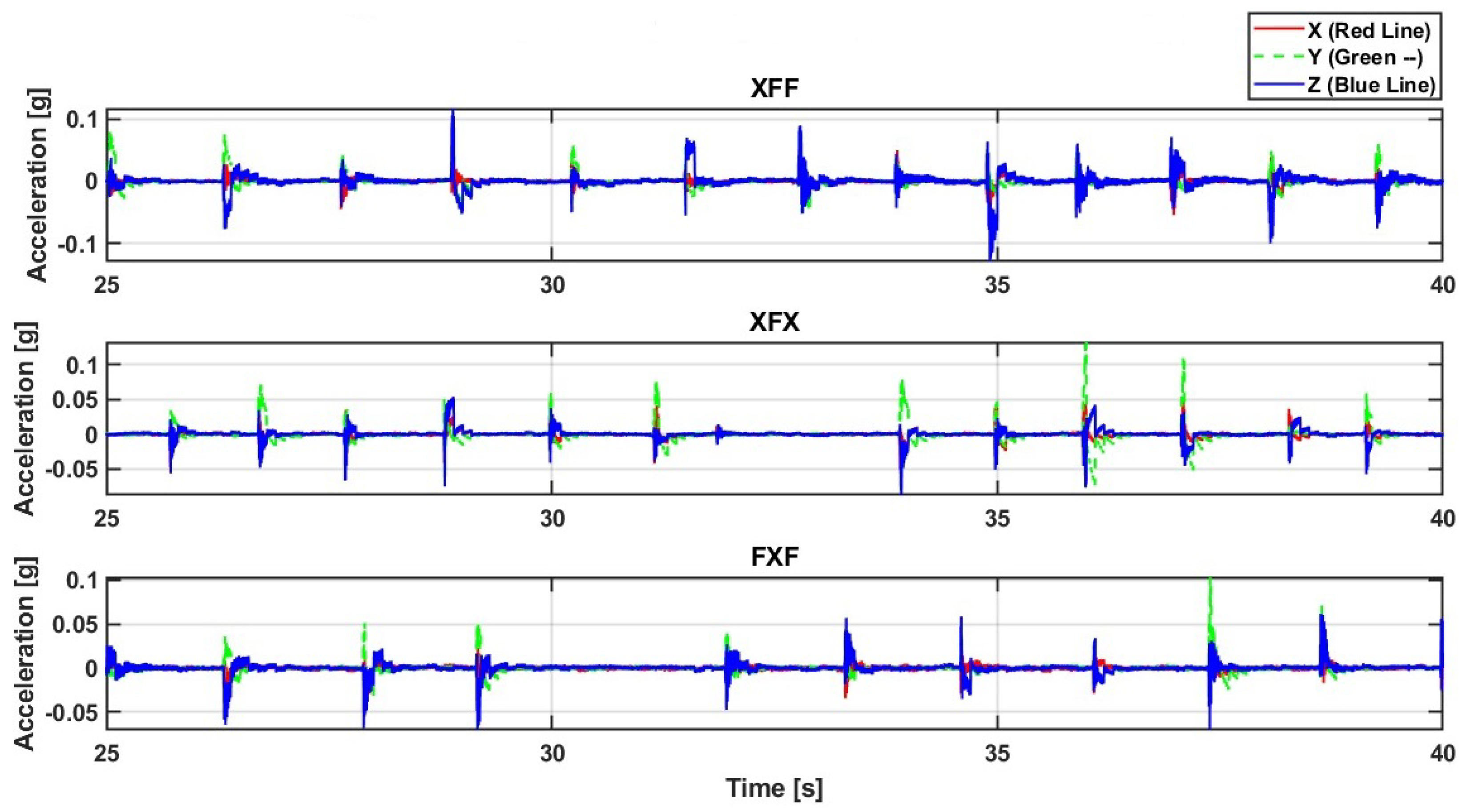
The time-domain acceleration signals shown in Figure 8 reveal key differences in the dynamic response of the system under three boundary condition configurations. Across all cases, the Z-axis exhibits the dominant acceleration response, confirming that the primary motion occurs out of plane—consistent with the intended spatial design of the structure. Under the XFF condition, the system shows the highest amplitude and the most frequent dynamic activity, indicative of reduced constraint and a broader vibrational spectrum. In contrast, the XFX and FXF configurations show more limited motion, characterized by smaller amplitudes and more regular spacing between impact events. These trends reflect the influence of increased structural constraints on the system’s dynamic behavior. Overall, the time-domain data highlight the sensitivity of the system’s response to boundary condition changes and support the use of direct acceleration measurements for evaluating modal characteristics in flexible multibody systems.
To investigate the dynamic behavior and extract the natural frequencies of the spatial double pendulum, a Fast Fourier Transform (FFT) analysis was conducted on time-domain acceleration data acquired from a triple-axis analog accelerometer (ADXL335). The data were recorded with a sampling rate of 10 kS/s over a total duration of 60 s. The FFT is a widely adopted signal processing technique that converts temporal vibration signals into the frequency domain, enabling the identification of dominant frequency components corresponding to the system’s natural modes of vibration.
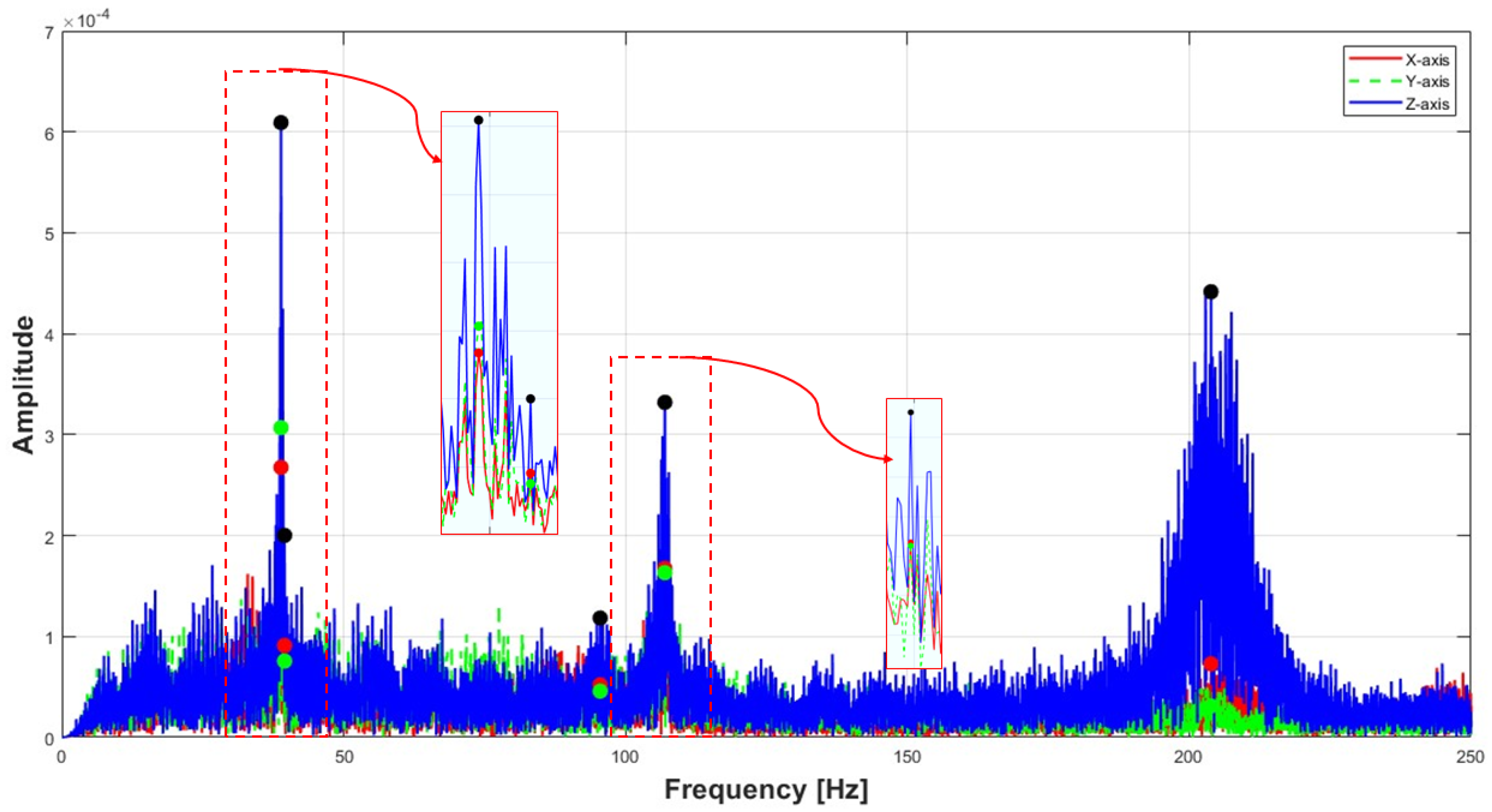
Figure 9 illustrates the frequency spectra obtained from the FFT analysis under the first boundary condition, XFF, which corresponds to a Fixed–Free–Free configuration, in which the first end of the structure is fixed. Experimentally, this configuration is implemented by activating the first electromagnet located at the base of the structure via a DC amplifier, as illustrated in Figure 6. The acceleration responses along the X, Y, and Z axes are plotted, with the Z-axis (blue) exhibiting the most dominant peaks, consistent with the system’s out-of-plane motion. Automatically detected peak frequencies are marked using circular indicators: black for the Z-axis, red for the X-axis, and green for the Y-axis. Red dashed boxes with zoomed-in insets highlight regions where multiple natural frequencies are clustered. Among the three tested boundary conditions, the XFF configuration results in the lowest overall natural frequency range, which is expected due to the minimal constraint applied to the system. This figure provides a comprehensive frequency-domain representation of the structure’s vibrational characteristics during free oscillation. The corresponding natural frequencies identified for the XFF condition are summarized in Equation (17).
ω F F T = 38.8667 39.5 95.5 106.967 203.867 T
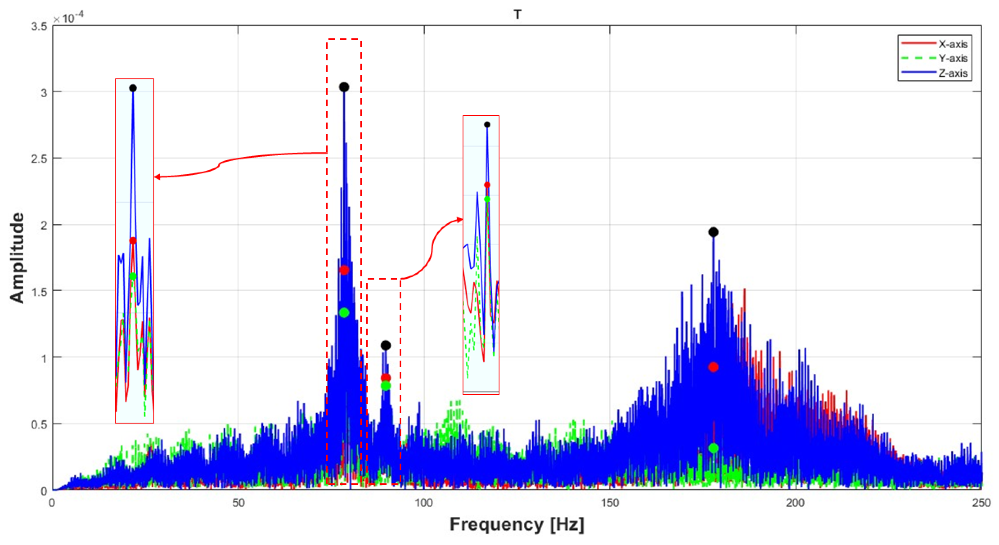
Figure 10 shows the frequency spectrum corresponding to the second boundary condition—Free–Fixed–Free (FXF). This configuration is implemented by activating the second and third electromagnets, located at the midsection of the structure along the X-axis, as shown in Figure 6, while keeping both ends of the structure unconstrained. The FXF boundary condition introduces intermediate constraint levels, producing natural frequencies that fall between those observed for the XFF and XFX cases.
The resulting spectrum reveals several prominent resonant peaks, particularly along the Z-axis (blue), with strong responses at approximately 78.48 Hz and 89.68 Hz , and a third peak appearing near 200 Hz , specifically at 177.81 Hz . Compared to the XFX configuration, the FXF spectrum exhibits broader frequency bands, suggesting the presence of closely spaced modes or possible mode coupling. Notably, cross-axis responses in the X (red) and Y (green) directions show energy near the Z-axis resonances, indicating structural asymmetry and inter-axis modal interaction. Zoomed-in regions emphasize the spectral clustering of these modes.
Overall, the FXF condition yields moderately sharp resonances and an intermediate degree of broadband vibrational activity. The corresponding natural frequencies are summarized in Equation (18).
ω F F T = 78.4851 89.6824 177.805 T
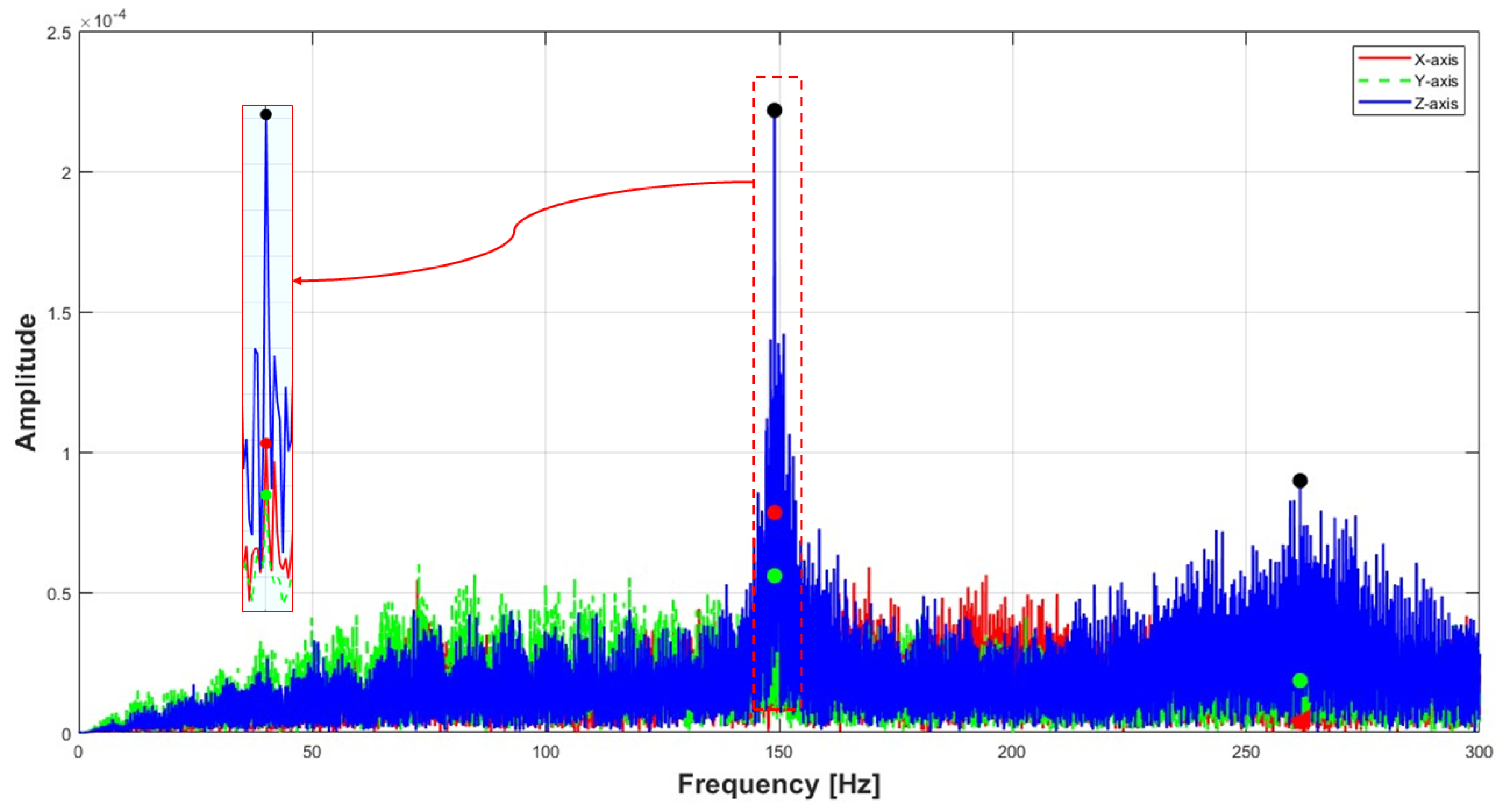
Figure 11 illustrates the frequency spectrum of the acceleration response under the third boundary condition, XFX. In this configuration, the first and fourth electromagnets—positioned at the two ends of the structure—are activated via a DC amplifier to implement a Fixed–Free–Fixed setup, as shown in Figure 6. The FFT analysis, based on acceleration data sampled at 10 kS / s over 60 s , reveals distinct resonant peaks, primarily along the Z-axis, with prominent amplitudes around 149 Hz and broader responses near 250 Hz .
Compared to the less constrained XFF and FXF configurations, the XFX boundary condition enforces symmetry and restricts motion at both ends. This increased stiffness results in higher natural frequencies and more sharply defined peaks. The strong spectral content along the Z-axis reflects intensified out-of-plane deformation, while the presence of energy in the X and Y directions near dominant peaks further suggests modal coupling and potential structural asymmetry. The more concentrated spectral energy and reduction in broadband noise indicate a more deterministic vibrational response.
Among all tested cases, the XFX configuration yields the highest range of natural frequencies due to its greater structural constraint. The corresponding natural frequencies are summarized in Equation (19).
ω F F T = 149.007 261.555 T
Upon reviewing the data presented in Table 1 and comparing the theoretical predictions with the experimental results, it is noteworthy that the natural frequencies extracted experimentally show strong agreement with those predicted by the FFR formulation across all three boundary conditions. The computed natural frequencies from the FFR model span a range from 38.76 Hz to 148.17 Hz , while the experimentally measured frequencies range from 38.86 Hz to 149 Hz . The minimal discrepancy between the two—less than 1% across the full range—demonstrates the accuracy and reliability of the proposed modeling approach.
This close correlation also highlights the structure’s suitability for applications involving out-of-plane vibrations across multiple directions, within an operational frequency range of approximately 39 Hz to 149 Hz .

3.2. Finite Element Verification of Modal Results

Finite Element Analysis (FEA) is a cornerstone in structural dynamics for validating theoretical and experimental results [6,32]. In the present study, numerical simulations were carried out using ANSYS Mechanical to verify the modal behavior of the spatial double-pendulum structure previously analyzed through the extended Floating Frame of Reference (FFR) formulation and experimental testing. This verification aims to assess the consistency of natural frequencies and mode shapes across computational, analytical, and physical domains.
The geometry of the structure comprises three beam segments with circular cross-sections (8 mm diameter) and lengths of 160 mm, 140 mm, and 150 mm, respectively. The structure was modeled using 3D beam elements (BEAM188) in ANSYS, which are suitable for capturing bending and axial behaviors in slender structures [26]. Material properties are defined according to the actual fabricated prototype, which is constructed from plain carbon steel (mild steel), a commonly used structural-grade material. The material parameters used in the simulation are Young’s modulus ( E = 200 GPa), Poisson’s ratio of 0.29, and density of 7850 kg / m 3 , consistent with both the experimental setup and theoretical modeling assumptions.
The meshing strategy employed a coarse but optimized configuration using adaptive size functions and solid elements. The mesh was generated using an initial size seed based on the active assembly, with medium smoothing, fast transition, and a span angle center setting of coarse. Inflation was enabled with a smooth transition, a maximum of five layers, a growth rate of 1.2, and a transition ratio of 0.272. The resulting mesh consisted of 8452 nodes and 1595 elements, balancing computational efficiency with accuracy in capturing the first five vibration modes. The mesh quality and density were sufficient to ensure convergence and capture detailed modal behavior, without the need for further refinement.
To simulate real-world constraints and evaluate the influence of different support scenarios, three boundary conditions were modeled and analyzed: Fixed–Free–Free (XFF), Fixed–Free–Fixed (XFX), and Free–Fixed–Free (FXF). Each configuration was created in a separate simulation to isolate its modal characteristics. The XFF case involved fully constraining the first node of the structure, coinciding with the location of the first electromagnet, as illustrated in Figure 7. For the XFX case, both the first and second electromagnets were considered fixed, effectively clamping both ends of the beam assembly. The FXF configuration introduced a constraint at the midpoint of the second beam segment, aligned with the position of the third and fourth electromagnets shown in Figure 7. These three setups correspond directly to the boundary conditions used in the extended FFR formulation and experimental tests.
The simulation results revealed that the XFF condition produced the lowest range of natural frequencies, with the first mode appearing at approximately 36.49 Hz, reflecting the minimal constraint on the system. In contrast, the XFX configuration, which applied full constraints at both ends, yielded the highest frequency values, with the first three modes exceeding 146.91 Hz, consistent with the stiffer dynamic response expected of a fully supported structure. The FXF configuration generated intermediate frequency values, demonstrating the influence of fixing the midsection while allowing the outer ends to vibrate freely. A detailed summary of the natural frequencies for all three boundary conditions—XFF, FXF, and XFX—obtained from the ANSYS (2023 R2) simulations is presented in Table 2.
Comparison with results from the extended FFR formulation and experimental testing confirms strong alignment across all platforms. The FFR analysis predicted a frequency range from 38.76 Hz to 148.17 Hz, while experimental modal tests recorded values from 38.86 Hz to 149 Hz. Specifically, under the XFF configuration, the first natural frequency differed by less than 2.5 Hz among ANSYS, FFR, and experimental data. Likewise, the XFX condition consistently produced first-mode frequencies near 149 Hz in all three methods. The total frequency span across the three configurations—approximately 110 Hz—was nearly identical for FEA, theory, and experiment.
A consolidated summary of these extracted natural frequencies is presented in Table 3, offering a side-by-side comparison for each boundary condition across the three approaches. On average, the FFR model demonstrates a 94.4% agreement with experimental results and a 93.5% match with ANSYS simulations across all configurations and modes. The strong agreement across computational, theoretical, and experimental datasets validates the reliability of the proposed discontinuous FFR formulation, particularly in its ability to accurately capture slope discontinuities at segment interfaces. This convergence not only confirms the fidelity of the experimental setup but also demonstrates the effectiveness of the implemented boundary constraints and meshing strategy in capturing the true dynamic behavior of the spatial flexible multibody system.

4. Conclusions

This study presented a comprehensive investigation into the modal characteristics of a spatial discontinuous structure using an extended Floating Frame of Reference (FFR) formulation. The proposed methodology integrates theoretical modeling, finite element analysis via ANSYS, and experimental validation using a tri-axis analog accelerometer and a custom-built test-rig equipped with electromagnet-based boundary constraints. Three boundary conditions—Fixed–Free–Free (XFF), Free–Fixed–Free (FXF), and Fixed–Free–Fixed (XFX)—were implemented to explore the system’s dynamic behavior under varying constraint scenarios.
The results reveal strong agreement among the natural frequencies obtained through the FFR formulation, finite element simulation, and experimental measurements. Across all configurations, the natural frequencies span a range from approximately 38.87 Hz to 149 Hz , demonstrating the accuracy and robustness of the developed model in capturing slope discontinuities in flexible multibody systems. As expected, the XFX condition exhibits the highest frequency response due to increased structural stiffness, whereas the XFF condition yields the lowest due to minimal constraints. The FXF configuration produces intermediate values and exhibits signs of modal coupling, reflecting the influence of mid-span support.
The consistent correlation among the theoretical, computational, and experimental results validates both the accuracy of the discontinuous FFR approach and the reliability of the experimental setup. This validated framework enables the accurate modeling and tuning of directionally sensitive systems with geometric discontinuities.
In real-time implementation, the computational efficiency of the proposed extended FFR formulation allows the simulation of discontinuous structures at different scales, enabling the selection of an optimal scale that matches the characteristics of the available wave data for enhanced performance in practical applications.
The numerical stability considerations of the extended FFR formulation are consistent with stabilization strategies previously developed for large-rotation and large-deformation ANCF models [9,18,33], and these methods have proven equally effective for FFR-based small-deformation problems, ensuring well-conditioned stiffness matrices and robust convergence in large-scale implementations.

Author Contributions

Conceptualization, A.A.N., A.M.R.F.E.-B. and M.M.; methodology, software, validation, investigation, and writing—original draft, S.M.K.; experimental validation, S.M.K., A.A.N. and M.M.; data curation, A.M.R.F.E.-B.; writing—review and editing, A.A.N. All authors have read and agreed to the published version of the manuscript.

Funding

This research received no external funding.

Acknowledgments

The first author gratefully acknowledges the Ph.D. grant provided by the Egyptian Ministry of Higher Education (MoHE). The author would like to extend thanks to E-JUST for providing an authentic software, which was used for programming the proposed methodologies and simulations. Also, a special gratitude to my supervisory board for their continues support during this research.

Conflicts of Interest

The authors declare that they have no conflicts of interest.

Abbreviations

The following abbreviations are used in this manuscript:
ANCFAbsolute Nodal Coordinate Formulation
FEAFinite Element Analysis
FFTFast Fourier Transform
FFRFloating Frame of Reference
FMBSsFlexible MultiBody Systems
FXFFree-Fixed-Free
XFFFixed-Free-Free
XFXFixed-Free-Fixed
Symbols
A i Transformation matrix
B 1 i j The connectivity matrix
B 2 i j The linear-transformation matrix
B D 1 i j The modified connectivity matrix
C i j The rotation matrix
K f D Overall stiffness matrix with slope discontinuities
K f f Overall stiffness matrix
L i j The length of the element
M f D Overall mass matrix with slope discontinuities
M f f Overall mass matrix
P i j An arbitrary point
R i The position of the origin of the body-fixed coordinate system, which corresponds to the floating frame
S i j X 0 i j The shape matrix
( u ¯ i j ,0)The position of point P i j in its undeformed state
( u ¯ i j ,f)The elastic deformation of the element
u ¯ i j The position of the point P i j in relation to the body-fixed coordinate system
( ( q i , f ) )The unconstrained vector of nodal coordinates for body i
r i j Position vector
ω Natural Frequency

References

  1. Shabana, A.A. Flexible multibody dynamics: Review of past and recent developments. Multibody Syst. Dyn. 1997, 1, 189–222. [Google Scholar] [CrossRef]
  2. Shabana, A.A. Theory of Vibration: An Introduction, 3rd ed.; Springer: Berlin/Heidelberg, Germany, 2018. [Google Scholar] [CrossRef]
  3. Shabana, A.A. Dynamics of Multibody Systems, 4th ed.; Cambridge University Press: Cambridge UK, 2013. [Google Scholar] [CrossRef]
  4. Géradin, M.; Cardona, A. Flexible Multibody Dynamics: A Finite Element Approach; John Wiley and Sons: Hoboken NJ, USA, 2001; Volume 4. [Google Scholar]
  5. Wasfy, T.; Noor, A. Computational strategies for flexible multibody systems. Appl. Mech. Rev. 2003, 56, 553–613. [Google Scholar] [CrossRef]
  6. Zienkiewicz, O.; Taylor, R.; Zhu, J. The Finite Element Method: Its Basis and Fundamentals. In The Finite Element Method: Its Basis and Fundamentals, 7th ed.; Butterworth-Heinemann: Oxford, UK, 2013; p. i. [Google Scholar] [CrossRef]
  7. Sugiyama, H.; Shabana, A.A.; Omar, M.A.; Loh, W.Y. Development of nonlinear elastic leaf spring model for multibody vehicle systems. Comput. Methods Appl. Mech. Eng. 2006, 195, 6925–6941. [Google Scholar] [CrossRef]
  8. Shabana, A.A. Definition of ANCF Finite Elements. J. Comput. Nonlinear Dyn. 2015, 10, 054506. [Google Scholar] [CrossRef]
  9. Nada, A.; Bishiri, A. Floating Frame of Reference formulation for modeling flexible multi-body systems in premise operational conditions. J. Vib. Control 2019, 25, 2706–2720. [Google Scholar] [CrossRef]
  10. Nada, A.; Hussein, B.; Megahed, S.; Shabana, A. Floating Frame of Reference and Absolute Nodal Coordinate Formulations in the Large Deformation Analysis of Robotic Manipulators: A Comparative Experimental and Numerical Study. In Proceedings of the ASME 2009 International Design Engineering Technical Conferences and Computers and Information in Engineering Conference (IDETC/CIE 2009), San Diego, CA, USA, 30 August–2 September 2009. [Google Scholar] [CrossRef]
  11. Nowakowski, C.; Fehr, J.; Fischer, M.; Eberhard, P. Model Order Reduction in Elastic Multibody Systems using the Floating Frame of Reference Formulation. IFAC Proc. Vol. 2012, 45, 40–48. [Google Scholar] [CrossRef]
  12. Korkealaakso, P.; Mikkola, A.; Rantalainen, T.; Rouvinen, A. Description of joint constraints in the floating frame of reference formulation. Proc. Inst. Mech. Eng. Part K J.-Multi-Body Dyn. 2009, 223, 133–145. [Google Scholar] [CrossRef]
  13. Schilder, J.P. A New Floating Frame of Reference Formulation for Flexible Multibody Dynamics; University of Twente: Enschede, The Netherlands, 2017. [Google Scholar]
  14. De Ponti, J.M.; Colombi, A.; Ardito, R.; Braghin, F.; Corigliano, A.; Craster, R.V. Graded elastic metasurface for enhanced energy harvesting. New J. Phys. 2020, 22, 013013. [Google Scholar] [CrossRef]
  15. Huang, S.; Dong, G.; Zhou, M. Low-Frequency Broadband Piezoelectric Vibration Energy Harvester Based on Double L-shaped Beam Structures. J. Vib. Eng. Technol. 2022, 10, 3179–3189. [Google Scholar] [CrossRef]
  16. Wang, W.; Chen, J.; Zivkovic, A.S.; Xie, H. A Fourier Transform Spectrometer Based on an Electrothermal MEMS Mirror with Improved Linear Scan Range. Sensors 2016, 16, 1611. [Google Scholar] [CrossRef]
  17. Ahmed, R.; Mir, F.; Banerjee, S. A review on energy harvesting approaches for renewable energies from ambient vibrations and acoustic waves using piezoelectricity. Smart Mater. Struct. 2017, 26, 085031. [Google Scholar] [CrossRef]
  18. Bishiri, A.; Nada, A. Modal Analysis and Experimental Validation of Continuum Multibody Models with Slope Discontinuity and Restricted Deformations. J. Vib. Eng. Technol. 2025, 13, 235. [Google Scholar] [CrossRef]
  19. Heo, S.; Koo, W. Dynamic Response Analysis of a Wavestar-Type Wave Energy Converter Using Augmented Formulation in Korean Nearshore Areas. Processes 2021, 9, 1721. [Google Scholar] [CrossRef]
  20. Kim, D.; Bae, Y.H. Multibody Analysis of Wave Energy Converters and a Floating Platform in the Time Domain. J. Mar. Sci. Eng. 2024, 12, 265. [Google Scholar] [CrossRef]
  21. Li, Y.; Ren, N.; Li, X.; Ou, J. Hydrodynamic Analysis of a Novel Modular Floating Structure System Integrated with Floating Artificial Reefs and Wave Energy Converters. J. Mar. Sci. Eng. 2022, 10, 1091. [Google Scholar] [CrossRef]
  22. Sui, S.; Cao, L.; Gao, Y.; Huo, Z.; Chen, Q. Numerical Simulation Study on Hydrodynamic Characteristics of Offshore Floating Photovoltaics. J. Mar. Sci. Eng. 2025, 13, 142. [Google Scholar] [CrossRef]
  23. Ling, H.; Ying, L.; Bin, Y.; Yueqin, Z. Dynamic modeling and simulation of flexible beam finite rotation with ANCF method and FFR method. Mechanics 2018, 24, 715–724. [Google Scholar] [CrossRef]
  24. Slimak, T.; Zwölfer, A.; Todorov, B.; Rixen, D. A machine learning approach to simulate flexible body dynamics. Multibody Syst. Dyn. 2025, 64, 515–541. [Google Scholar] [CrossRef]
  25. Angeli, A.; Desmet, W.; Naets, F. Deep learning for model order reduction of multibody systems to minimal coordinates. Comput. Methods Appl. Mech. Eng. 2021, 373, 113517. [Google Scholar] [CrossRef]
  26. Moaveni, S. Finite Element Analysis: Theory and Application with Ansys; Pearson Education Limited: New York, NY, USA, 2015. [Google Scholar]
  27. Wittenburg, J. Dynamics of Multibody Systems; Springer: Berlin/Heidelberg, Germany, 2008. [Google Scholar] [CrossRef]
  28. Wallrapp, O. Standardization of Flexible Body Modeling in Multibody System Codes, Part I: Definition of Standard Input Data*. Mech. Struct. Mach. 1994, 22, 283–304. [Google Scholar] [CrossRef]
  29. Flores, P.; Ambrosio, J.; Claro, J.C.; Lankarani, H.M. Kinematics and dynamics of multibody systems with imperfect joints: Modeling and numerical simulation. Multibody Syst. Dyn. 2008, 20, 105–134. [Google Scholar] [CrossRef]
  30. Bauchau, O.A.; Craig, J.I. Structural Analysis: With Applications to Aerospace Structures; Springer: Dordrecht, The Netherlands, 2009. [Google Scholar] [CrossRef]
  31. Gere, W.; James, M.; Weaver, J. Analysis of Framed Structures; University Series in Civil Engineering and Applied Mechanics; Van Nostrand: Princeton, NJ, USA, 1965; p. xi + 475. [Google Scholar]
  32. Cook, R.D.; Malkus, D.S.; Plesha, M.E.; Witt, R.J. Concepts and Applications of Finite Element Analysis; John Wiley & Sons, Inc.: Hoboken, NJ, USA, 2007. [Google Scholar]
  33. Nada, A.; Bayoumi, M. Development of a constraint stabilization method of multibody systems based on fuzzy logic control. Multibody Syst. Dyn. 2024, 61, 233–265. [Google Scholar] [CrossRef]
Figure 1. Representative engineering applications of the FFR approach.
Asi 08 00118 g001
Figure 2. 3D beam element within FFR formulation.
Asi 08 00118 g002
Figure 3. 3D Beam within FFR formulation for discontinuous structure.
Asi 08 00118 g003
Figure 4. Representative flexible structures exhibiting slope discontinuities: (a) In-plane inclined beam (b) In-plane C section (c) Out-of-plane spatial double-L configuration.
Asi 08 00118 g004
Figure 5. Laboratory test rig configuration and instrumentation: (1) computer with monitor, (2) NI PCI-6259 data acquisition, (3) vice clamping the frame holding the spatial structure, (4) frame (supporting double-pendulum structure), (5) EZ GP-4303D DC Power Supply.
Asi 08 00118 g005
Figure 6. Experimental layout of a spatial double-pendulum test rig with four round electromagnets and a triple-axis accelerometer.
Asi 08 00118 g006
Figure 7. Experimental test rig for a spatial double-pendulum with structural discontinuities: (6) a spatial double-pendulum structure, (7) four round electromagnets with one 3-axis accelerometer.
Asi 08 00118 g007
Figure 8. Collected accelerations along a spatial strcture under three boundary conditions, totaling 15 signals.
Asi 08 00118 g008
Figure 9. FFT spectra of acceleration signals under XFF condition ( 10 kS / s , 60 s duration).
Asi 08 00118 g009
Figure 10. FFT spectra of acceleration signals under FXF condition ( 10 kS / s , 60 s duration).
Asi 08 00118 g010
Figure 11. FFT spectra of acceleration signals under XFX condition ( 10 kS / s , 60 s duration).
Asi 08 00118 g011
Table 1. Natural frequencies of the spatial double pendulum under different boundary conditions using FFR.
Natural FrequencyXFFXFXFXF
ω 1 38.76148.1777.62
ω 2 45.68270.6789.32
ω 3 95.71211.57
ω 4 115.89 
ω 5 219.24 
Table 2. Natural frequencies of the spatial double pendulum under different boundary conditions using ANSYS.
Natural FrequencyXFFXFXFXF
ω 1 36.49146.9174.29
ω 2 40.31250.7879.59
ω 3 99.79218.97
ω 4 108.97 
ω 5 205.96 
Table 3. Comparison of natural frequencies (Hz) obtained from FFR, experimental FFT analysis, and ANSYS simulation for all boundary conditions.
ModeBoundary ConditionFFR (Hz)Experiment (Hz)ANSYS (Hz)
ω 1 XFF38.7638.8736.49
ω 2 45.6839.5040.31
ω 3 95.7195.5099.79
ω 4 115.89106.97108.97
ω 5 219.24203.87205.96
ω 1 FXF77.6278.4974.29
ω 2 89.3289.6879.59
ω 3 211.57177.81218.97
ω 1 XFX148.17149.01146.91
ω 2 270.67261.56250.78
Disclaimer/Publisher’s Note: The statements, opinions and data contained in all publications are solely those of the individual author(s) and contributor(s) and not of MDPI and/or the editor(s). MDPI and/or the editor(s) disclaim responsibility for any injury to people or property resulting from any ideas, methods, instructions or products referred to in the content.